1
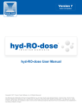
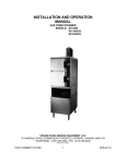
SN-3E and SN-5E
ELECTRIC CONVECTION STEAMER
INSTALLATION – OPERATION – MAINTENANCE
BLODGETT OVEN COMPANY
IMPORTANT NOTES FOR INSTALLATION AND OPERATION
www.blodgett.com
44 Lakeside Avenue, Burlington, Vermont 05401 USA Telephone (800) 331-5842, (802) 860-3700 Fax: (802) 864-0183
1 B (3/06)
S00059 Rev
IMPORTANT NOTES FOR INSTALLATION AND OPERATION
This is the safety alert symbol. It is used to alert you to potential
personal injury hazards. Obey all safety messages that follow this
symbol to avoid possible injury or death.
WARNING: Improper installation, operation, adjustment, alteration,
service or maintenance can cause property damage, injury or death.
Read the installation, operating and maintenance instructions
thoroughly before installing, operating or servicing this equipment.
Intended for commercial use only. Not for household use.
This manual should be retained for future reference.
2
TABLE OF CONTENTS
DESCRIPTION
PAGE
Important Notes For Installation and Operation .................................................................. 2
Service Connection.............................................................................................................. 4
1.0 Installation Instructions ............................................................................................... 5
2.0 Testing Procedures ..................................................................................................... 9
3.0 Operation .................................................................................................................. 10
4.0 Cleaning .................................................................................................................... 13
5.0 Maintenance ............................................................................................................. 14
6.0 Adjustment for High Altitude ...................................................................................... 15
7.0 Troubleshooting ........................................................................................................ 16
3
SERVICE CONNECTION
ELECTRICAL CONNECTION: Ø1 1/8" hole for electrical connection. Rating to be as specified on data plate.
DRAIN: 1"IPS to open floor drain. No solid connection. 24" length before open air gap opening (No bends or elbows).
GENERATOR WATER: 3/8" O.D. tubing at 25-50 PSI(170-345 kPa)
C
CONDENSING WATER: 3/8" O.D. tubing at 25-50 PSI(170-345 kPa)
WATER QUALITY STATEMENT
WATER QUALITY IS THE MAJOR FACTOR AFFECTING THE PERFORMANCE OF YOUR APPLIANCE. IF YOU ARE UNSURE OF WATER
QUALITY, CONSULT A LOCAL WATER TREATMENT SPECIALIST AND HAVE THE WATER ANALYZED. YOUR WATER SUPPLY MUST BE
WITHIN THESE GENERAL GUIDELINES:
LESS THAN 60 PPM
TOTAL DISSOLVED SOLIDS
LESS THAN 20 PPM
TOTAL ALKALINITY
LESS THAN 13 PPM
SILICA
LESS THAN 1.5 PPM
CHLORINE
7.0-8.5
pH FACTOR
WATER WHICH FAILS TO MEET THESE STANDARDS SHOULD BE TREATED BY INSTALLATION OF A WATER CONDITIONER.
FAILURE OR MALFUNCTION OF THIS APPLIANCE DUE TO POOR WATER QUALITY IS NOT COVERED UNDER WARRANTY.
ELECTRICAL CHARACTERISTICS
MODEL
kW
Phase
SN-3E standard
7.5
SN-3E option
10
SN-5E standard
15
AMPS PER LINE
415V
208V
220V
240V
380V
1
36
34
31
n/a
3
21
20
18
11
10
9
7
1
48
46
42
n/a
n/a
n/a
n/a
3
28
26
24
15
14
12
10
1
72
68
63
n/a
n/a
n/a
n/a
3
42
39
36
23
21
18
14
17 [432]
n/a
480V
600V
n/a
n/a
1.75 [45]
27.5 [698]
3 [76]
1.75 [45]
15 [381]
24 [610]
1.13 [29]
1 [25]
12.5 [318]
19 [483]
1.5 [38]
SN-3E
SN-5E
SN-3E
SN-5E
1/2-NPT DELIME INLET
15.12 [384]
21.62 [549]
DIMENSIONS ARE IN INCHES [MM]
OPTIONAL LEGS
20 [508]
23.5 [597]
4
4 [102]
2 [51]
1.0 INSTALLATION INSTRUCTIONS
LOCATION
Allow space for plumbing and electrical connections. Minimum clearances are 2" on the sides
and 6" on the back for proper air circulation. Allow adequate access for operating and servicing
the steamer (36" at the front of the steamer and 15" above the steamer).
LEGS (OPTIONAL)
If the optional 4" adjustable legs are used, remove the four levelling feet on the bottom of the
steamer.
LEVELING
Using a spirit level or pan of water in bottom of steamer chamber, adjust feet to level steamer
front to back and side to side. After drain is connected, check for level by pouring water onto
the floor of the compartment. All water should drain through opening in rear.
ANCHORING STEAMER
1. Place steamer in desired location with level counter top and mark four corners. Remove
steamer and drill ½" holes as indicated in Figure 1.
2. Apply a bead of RTV or other equivalent sealant around bottom perimeter edge of steamer.
Failure to comply with this requirement will void the NSF label.
3. Set steamer on counter and bolt down securely with 3/8 - 16 bolts.
FIGURE 1
5
DRAIN CONNECTIONS
The drain connection must be 1" IPS vertically down, preferably with one elbow only, and
maximum length of 6 feet, piped to an open air gap type drain.
FIGURE 2
CAUTION: In order to avoid any back pressure in the steamer, DO NOT
connect solidly to any drain connection.
WATER CONDITIONING
It is important that the water supply connected to this steamer be softened to no more than 2.0
grains of hardness and have a pH of 6 to 7.5. This degree of hardness can be easily obtained
with the use of properly maintained water softener. The use of a water meter will determine the
water consumption and when the water softener needs regeneration or recharging. Failure to
comply with these water condition standards may void the warranty.
Untreated water contains scale producing minerals which can precipitate onto the surfaces in
the steam generator. Due to the temperatures in the steam generator, the minerals can bake
onto the surfaces and components. This can result in early component failure and reduced
product life.
Mineral scale on components causes several problems:
1. The surfaces of the heating devices become coated with scale, reducing the heat transfer
efficiency. This can produce hot spots on the heating elements and result in premature
failure.
6
2. The water level probes become coated with scale. Scale bridges across the probe insulator
from the metal extension which senses the water level in the steam generator shell. Once
this scale becomes wet, the water level control is unable to maintain the proper water level
in the steam generator. This situation may cause an electric heating element to fail as a
result of the element not being adequately covered by water.
Strainers and filters will NOT remove minerals from the water.
VENT HOOD
Some local codes may require the steamer to be located under an exhaust hood.
Information on the construction and installation of ventilating hoods may be obtained from the
standard for “Vapor Removal from Cooking Equipment,” NFPA No. 96 (latest edition).
STACKING KITS
Follow instructions accompanying the stacking kits for installation of stacked steamers.
ELECTRICAL CONNECTIONS
WARNING: Electrical and grounding connections must comply with applicable
portions of the National Electrical Code and/or other local electrical codes.
WARNING: Disconnect electrical power supply and place a tag at the
disconnect switch to indicate that you are working on the circuit.
7
ELECTRICAL CONNECTIONS
Use copper wire suitable for at least 200 degrees Fahrenheit (90 degrees Celsius). The
steamer must be grounded. The wiring diagram is located on the right side panel as you face
the steamer.
PLUMBING CONNECTIONS
WARNING: Plumbing connections must comply with applicable sanitary,
safety and plumbing codes.
There is a 3/8" copper tube water line at the rear of the unit. Should your unit have the optional
split water lines, each will be marked to indicate condensate or boiler feed. The condensate
feed must be cold water and the boiler feed may be either cold or hot water. Providing hot
water feed to the generator will reduce recovery time during cooking.
8
2.0 TESTING PROCEDURES
WARNING: The steamer and its parts are hot. Use care when operating,
cleaning or servicing the steamer. The cooking compartment contains live
steam. Stay clear while opening door.
Once the steamer is installed and all mechanical connections have been made, thoroughly test
the steamer before operation.
1. Check that proper water, drain and electrical connections have been made.
2. Turn main power switch ON. After approximately 15 minutes, the READY light should come
on, indicating that the water temperature is 205 degrees Fahrenheit.
3. When the READY light comes on, set timer to the “5 minute” position. With door open,
observe that no steam is entering the compartment and that the COOKING light is OFF.
4. Close compartment door. The COOKING light should now be illuminated and steam should
be heard entering the compartment after about 45 seconds.
5. Check drain line to ensure that water from cold water condenser is flowing through the drain
line.
6. Open compartment door and observe that steam supply to chamber is cut off (READY light
should again come on as COOKING light goes off.
7. Close compartment door and let cooking cycle finish. When the timer returns to “0" position,
a buzzer will sound signalling the end of the cooking cycle. Buzzer must be manually turned
off by setting the timer to its OFF position.
8. To shut down steamer, turn main power switch OFF and leave compartment door slightly
open.
9
3.0 OPERATION
Your steamer has been factory set when ON to maintain water temperature during the READY
phase at approximately 205 degrees Fahrenheit (just below water boiling point).
CONTROLS
Ready Light
-
when lit, indicates steam chamber has reached 205 degrees
Fahrenheit and is ready for the cooking cycle.
Cooking Light
-
when lit, indicates that a cooking cycle is in progress
Timer
-
set the cooking time (0 to 60 minutes) - steam cooking will begin when
the door is closed. The cooking cycle will be interrupted if the door is
open during the cooking cycle; resume cooking by closing the door.
ON
-
when turned ON, boiler will automatically fill with water and begin
heating to READY temperature.
OFF
-
The boiler will drain.
DELIME
-
Closes the drain valve while CLR liquid is being poured into the
generator during the delime procedure.
Main Power Switch
OPERATION
1. When READY light comes on, preheat compartment for about one minute when steamer is
to be first used for the day or whenever the chamber is cold. Make sure compartment door
is closed.
2. When buzzer sounds, set time to OFF position. Your steamer is now ready for cooking.
3. With compartment preheated and READY light ON, place pans of food into the compartment
and close the door.
4. Set timer to desired cooking time. (The cooking cycle may be interrupted at any time by
opening the door. To resume operation, close the door.)
5. At the end of the cooking cycle, the buzzer will sound, the COOKING light will go off and
steam supply to the compartment will cease. Turn the timer to the OFF position to silence
the buzzer.
WARNING: Live steam and accumulated hot water in the compartment
may be released when the door is opened.
10
WARNING: An obstructed drain can cause personal injury or property
damage.
SHUT DOWN
Turn main power switch OFF. The steam generator will automatically drain.
CONSTANT STEAM FEATURE - OPTIONAL FEATURE
A switch has been added to control this feature. It is located below the timer under the heading
“COOKING MODE”.
OPERATION WITH THIS FEATURE
Operation for Timed Cooking
This switch must be positioned to the right, towards the heading “TIMED COOKING”. The
operator then must select the time required for the cooking by setting the timer dial to the
desired time from “0 to “60" minutes. At the end of the cook time an audible buzzer will sound.
Operation for Constant Steam
The switch must be positioned to the left towards the heading “CONTINUOUS COOKING”. This
mode will provide continuous steam to the cooking chamber until the operator either turns the
selector switch to the “TIMED COOKING” position, or turns the power switch to the “OFF”
position.
SHUT DOWN
Turn timer dial to the “OFF” position. Turn main power switch to the “OFF” position.
11
STEAM COOKING
Your steamer efficiently cooks vegetables or other foods for immediate serving. Steam
cooking should be carefully time controlled. Keep hot-food-holding-time to a minimum to
produce the most appetizing results. Prepare small batches, cook only enough to start
serving, then cook additional amounts to meet demand. Separate frozen foods into
smaller pieces to allow more efficient cooking.
Use a pan cover for precooked frozen dishes that cannot be cooked in the covered
containers in which they are packed if they require more than 15 minutes of cooking
time. When a cover is used, approximately one-third additional cooking time is
necessary.
Cooking time for frozen foods depends on amount of defrosting required. If time
permits, allow frozen foods to partially thaw overnight in a refrigerator. This will reduce
their cooking time.
PREPARATION
Prepare vegetables, fruits, meats, seafood and poultry normally by cleaning, separating,
cutting, removing stems, etc. Cook root vegetables in a perforated pan unless juices are
being saved. Liquids may be collected in a solid 12 inch by 20 inch pan placed under a
perforated pan. Perforated pans are used for frankfurters, wieners and similar items
when juices do not need to be preserved. Solid pans are good for cooking puddings,
rice and hot breakfast cereals. Vegetables and fruits are cooked in solid pans to
preserve their own juices. Meats and poultry are cooked in solid pans to preserve their
own juices or to retain broth. Canned foods may be heated in their opened cans (cans
placed in 12 inch by 20 inch solid pans) or the contents may be poured into solid pans.
DRAINING THE BOILER
Drain boiler after each day’s use to flush out minerals and minimize scale build-up. The
boiler drains automatically for about 6 minutes after you turn the main power switch off.
12
4.0 CLEANING
At the end of each day, or between cooking cycles if necessary:
1. Turn main power switch OFF.
2. Remove pans and racks from compartment and wash in sink.
3. Remove drain screens from inside compartment drains. Using a plastic bottle brush
and mild detergent, clean inside the drain opening ensuring there is no food residue
or blockage. Clean the drain screen and replace in its original position.
4. Wash compartment interior with clean water.
5. Use warm soapy water with a cloth or sponge to clean exposed bead of door gasket,
rinse with warm clear water and wipe with a dry cloth.
6. Wipe surfaces which touch door gasket with a cloth or sponge and warm soapy
water, rinse with warm clear water and wipe with a dry cloth. Do not apply food
oils or petroleum solvents or lubricants directly to door gasket or surfaces
which touch door gasket.
7. Keep cooking compartment drain working freely. After cooking grease producing
foods, operate steam with compartment empty for 30 minutes at end of the day, or
pour ½ gallon of warm soapy water down the drain, followed by ½ gallon of warm
clear water.
8. Leave door slightly open when steamer is not in use.
Weekly, or more often if necessary:
Clean exterior with a damp cloth and polish with a soft dry cloth. Use a non-abrasive
cleaner to remove discolorations.
13
5.0 MAINTENANCE
COLD WATER CONDENSER
The steamer is equipped with a cold water condenser in the rear of the cooking chamber
which helps to condense the steam prior to discharge into the drain. The steamer freely
vents itself by the negative pressure created by the condensate water drainage. This
negative pressure prevents steam leakage around the door gasket and helps draw the
steam through the cooking compartment. Steam leakage at the door may indicate a
plugged or improperly installed drain.
REMOVAL OF SCALE DEPOSITS
It is recommended that your steamer be delimed once a month, or more often if
necessary.
Should your steamer develop a heavy buildup of lime scale deposits, use CLR.
Before beginning deliming procedures, ensure that water is not overflowing into the
cooking compartment.
The generator tank has a removable sealed tank cover. The main purpose of the
removable cover is for inspection of the interior of the tank for lime build up and easy
removal of large pieces of lime that will not flush out drain. Should the tank cover have
to be removed, check condition of sealing gasket before replacing cover. The hold down
bolts are to be tightened to 160 inch pound torque each.
WARNING: Read and follow instructions on the CLR bottle. Use plastic or
rubber gloves to avoid skin contact. If CLR comes in contact with skin,
rinse with clean water.
1. Drain steam generator by setting the main power switch to OFF. Set cooking timer
to “O".
2. Set the main power switch to DELIME.
3. Delime port (A) is located on left side at rear of unit. Unscrew hex plug from elbow to
allow CLR solution to be poured in using a tube and funnel. Pour in 28 ounces of
solution into the generator (pour slowly to avoid spillage). Remove tube and funnel.
4. Screw the hex plug back into the elbow so that it is sealed.
5. Turn main power switch to ON.
6. Allow steamer to remain in READY cycle for 1-1/2 hours, then turn main power
switch OFF and allow generator to drain.
14
7. FLUSH CYCLE: Turn main power switch to ON. When READY light comes on, turn
main power switch to OFF to flush generator. Repeat this step three times to
completely flush generator.
8. Clean exterior and interior. Use a mild solution of soap and water. Rinse with clean
cloth. Dry with soft cloth. Leave compartment door open when not in use.
The steamer is now ready for use. Turn off for overnight shutdown.
6.0 ADJUSTMENT FOR HIGH ALTITUDE LOCATIONS
The steamer has been factory set so that when it is ON and during the READY phase, it
will maintain water temperature in the steam generator tank at approximately 205
degrees Fahrenheit (just below water boiling point). However, for high altitude locations,
an authorized servicer must adjust the steamer to achieve this temperature. To adjust:
1. Remove side panel and turn control panel power switch to ON.
2. Open compartment door, and after about 15 minutes, steam will be seen, entering
the cooking compartment.
3. Turn thermostat shaft counterclockwise to lower temperature until steam just ceases
to enter cooking compartment and READY light goes on.
4. Replace side panel.
5. Follow TESTING PROCEDURES in this manual.
15
7.0 TROUBLESHOOTING
WATER FLOWS INTO DRAIN DURING SHUTDOWN
When steamer is shut down and cold water is running continuously into the open drain,
either or both solenoid valves did not close when steamer was turned off.
1. Disassemble solenoid valve(s) and examine for scale or foreign particles lodged in
diaphragm or core tube.
2. Clean valve(s) thoroughly and reassemble, or replace valve(s).
WATER OVERFLOWS INTO COOKING COMPARTMENT
When steamer is first turned on for the day, and the following conditions occur:
- READY light does not come on after about 15 minutes.
- Water begins to overflow into cooking compartment.
- Water fill solenoid valve is open.
Then any or all of these symptoms may indicate a problem with the operating probe due
to either:
1. A short between the operating probe terminal and body of the steamer. Call your
authorized servicer.
2. Excessive scale build-up on the operating probe. This acts as an “insulation” and
prevents the probe from sensing the water level. It is therefore unable to close the
water fill (solenoid) valve to shut off the water.
As a temporary solution, with power OFF, unscrew probes, check visually, and clean or
chip off scalant. Replace probe.
This problem is an indication of severe harmful water conditions which should be
corrected immediately to avoid damage to the components and ultimate malfunction of
the steamer. (See WATER QUALITY STATEMENT on page 4 of this manual).
16
HEATER ELEMENTS DO NOT COME ON
When the steamer is turned ON and heater elements do not activate, and the READY
light does not come on, then the contactors may be burned out. If a considerable
amount of “chattering” of contactors has been previously experienced, then the
thermostat bulb may be coated with scalant and unable to sense water temperature in
the boiler accurately, and therefore unable to control the contactors.
1. Replace contactors.
2. Unscrew thermostat bulb, clean off scalants and screw thermostat bulb back in.
This problem may be an indication of inadequate water quality and is not covered under
warranty. Have water quality analysed and corrected immediately to avoid complete
malfunction of the steamer.
UNIT SHUTS DOWN WHILE IN OPERATION
Pressure switch has been activated due to 5 psi (34 kPa) pressure in the generator tank.
Pressure in the generator tank is caused by plugged steam jet tubes or steam diverters,
due to scale or poor water conditions. Steam jet tubes/steam diverter will have to be
cleaned or replaced.
17