1
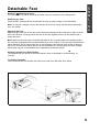
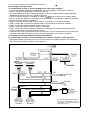
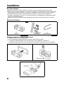
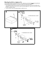
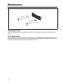
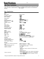
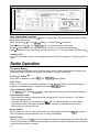
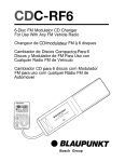
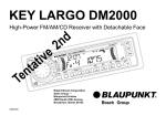
Cassette
t!P
Control
cassette et c~~t~~le de chanlelrr 6
Receptor cun Cassette y Control Camhiador
Radii-C~ssete corn CantrQ”le par t~~hi~d~r C
~~tQpedi~ i
Bosch Group
FCC Warning
The equipment has been tested and found to comply with the limits for a Class B device, pursuant
to Part 15 of the FCC Rules. These limits are designed to provide reasonable protection against
harmful interference in a residential installation. This equipment generates, uses, and can radiate
radio frequency energy, and, if not installed and used in accordance with instructions, may cause
harmful interference with radio communications. However, there is no guarantee that radio
interference will not occur in particular installation. If this equipment does cause harmful
interference to radio or television reception, which can be determined by turning the equipment off
and on, the user is encouraged to contact the dealer or an experienced Radio/TV technician for
help.
You are cautioned that any changes or modifications not expressly approved in this manual could
void your authority to operate this equipment.
Owner’s Record
The model and warranty numbers are located on the top of the unit. Record the warranty (serial)
number in the space provided below. Refer to these numbers whenever you call upon your
Blaupunkt dealer regarding this product.
Warranty Number
Attach Sales Receipt Here
2
Table of Contents
English
Espaiiol
FCC Warning.. .................................................. .2
Owner’s Record.. .............................................. .2
Features ........................................................... 4
Precautions ...................................................... .4
Detachable Face .............................................. .5
Electrical Connections and Installation ............ 6
Installation ........................................................ .8
Maintenance .................................................... 10
Specifications .................................................. 1 1
Location of Controls ........................................ 12
Instructions-General Operation .................... 12
Audio Operation .............................................. 13
Radio Operation .............................................. 14
Cassette Tape Player Operation .................... 15
CD Changer Control ....................................... 16
Troubleshooting Guide.. .................................. 17
Advertencias FCC ........................................ 36
Registro del Propietario ............................... 36
Caracteristicas ............................................. 37
Precauciones ................................................ 37
Panel Frontal Desmontable (Caratula). ....... 38
Conexiones Electricas e Instalacion ........... 39
Instalacion ................................................... .40
Mantenimiento .............................................. 43
Especificaciones .......................................... 44
Ubicacion de 10s Controles .......................... 45
lnstrucciones de Funcionamiento ................ 45
Funcionamiento de Audio ............................ 46
Funcionamiento de la Radio ........................ 47
Funcionamiento de Reproductor
de Cassette ............................................. 48
Control de Cambiador .................................. 49
Guia para la Solution de Problemas .......... 50
FranGais
Portuguese
Avertissement de la FCC ................................ 20
Archive du Proprietaire .................................. .20
Caracteristiques ............................................. .21
Precautions a Prendre ................................... .21
Face Avant Amovible ..................................... .22
Raccordements clectriques et Installation.. ... 23
Installation ...................................................... 25
Entretien ......................................................... 27
Specifications ................................................. .28
Emplacements des Commandes.. .................. 29
Mode d’Emploi/Fonctionnement General.. ..... 29
Fonctionnement de la Audio ........................... 31
Fonctionnement de la Radio.. ......................... 31
Fonctionnement du Lecteur de Cassette ....... 32
Commande du Changeur ................................ 33
Guide de Depannage ..................................... .35
Aviso da FCC ...............................................
Registro do Proprietario ...............................
Caracteristicas .............................................
Precaucoes ...................................................
Paine1 Removivel .........................................
Conexdes Electricas e lnstalacao ...............
Instalacao .....................................................
Manutencao ..................................................
Especificacoes .............................................
Posicao dos Controles .................................
Instrucoes-Funcionamento Geral ................
Funcionamento do Audo ..............................
Funcionamento do Radio.. ...........................
Funcionamento do Toca-Fitas .....................
Controle de Cambiador ................................
Guia para Solucao de Problemas ...............
51
51
52
52
53
54
56
58
59
60
60
61
62
63
64
66
3
1E NGLISH ]
Features
Congratulations on your purchase of this Blaupunkt Cassette Receiver. Its Codem III-US FM/AM
Tuner and Autoreverse Cassette Tape Player mechanism provide the ultimate in radio sound
reproduction. Its high-power amplifier and 4-Channel preamp output provide you with tremendous
system configuration flexibility. Its ability to control the Blaupunkt CDC-A05 and CDC-A071 CD
Changers (or CDC-A08 if adapter 7607898093 is used) lets you easily incorporate CD sound into
your car’s sound system.
l
l
l
Codem III-US Tuner Features:
- Multipath Management
- ASU Electrical impulse Noise Reduction
- Superior AM Frequency Response
- 15 FM/5 AM Presets, Including 5 FM &
5 AM Travelstore Presets
-Station Scan
-Local/Distant Seek & Manual Tuning
Cassette Tape Player Features
-Auto-Reverse Cassette Mechanism
- True Fast-Forward/Rewind
-Hard Permalloy Tape Head
-Radio Monitor with Radio Preset Access
-Dolby B Noise Reduction
CD Changer Control Features
-Controls CDCA071 Changer or CDC-A05
Changer
- Disc Select & Track Up/Down
-Audible Cue/Review
- Pause/Play
- Disc/Track Scans, Repeat and Mix
-Last Position Memory
l
l
Audio Features:
-35 Watts x 4 Channel Integrated Amplifier
-Dual-Level Fader
-Over 3 Volts of Distortion-Free Preamp Output
4-Channel, Low lmpendance (I 00 Q) Preamplifier
-2-Channel RCA Preamp Output Harness Included
- Bass,Treble, Balance, Fader Controls
-Adjustable Maximum Turn-On Volume
-Loudness Button
-Mute Button
Other Features:
-Detachable Face
-Green Illumination
-Display Priority Control
-Temporary Display Change Control
-Clock/Ignition-Off Clock Recall
-180x50x155mm (7x2x6l/ain.)
DIN/IS0 Chassis
-Detachable Wire Harness
-Snap-In DIN Sleeve & Mounting Hardware
-Side-Bracket Compatible
Your unit’s detachable front faceplate makes the unit useless to would-be thieves.
Designed, Engineered and Manufactured by Blaupunkt
Traffic Safetv and Precautions
l
l
l
l
l
4
Do not adjust your unit in difficult driving conditions that demand your full attention.
As the driver of a motor vehicle, it is your responsibility to pay attention to the traffic situation at all
times. Never use your unit in a way that could distract you.
Always make sure that you are still able to hear any warning signals coming from outside of the
vehicle, such as police or fire engine sirens, so that you can react accordingly.
If your vehicle was parked in direct sunlight resulting in a considerable rise in temperature inside
the vehicle, allow the unit to cool off before operating your unit.
You are cautioned that any changes or modifications not expressly approved in this manual could
void your warranty.
Detachable Face
Detaching & Attaching the Face:
The face of this unit can be detached and taken with you to prevent it from being stolen.
Detaching the Face:
Press the REL (Release) Button and detach the face by gently pulling it off as illustrated.
Note: Do not pull it straight out from the chassis. Be sure not to drop the face when detaching it
from the chassis.
Attaching the Face:
Apply the right hand side of the face to the chassis by sliding (part B) of the face to (part A) at the
front of the chassis. Gently push the left side of the face against the front of the chassis until it
snaps into place.
Note: Make sure that the face is inserted right side up. Do not press against the display window.
Do not press hard against the face when attaching it to the chassis, it may be easily attached with
gentle pressure. Do not expose the face to direct sunlight, heat sources such as hot air ducts or
leave it in a humid place. Never leave it on the dash board of a vehicle parked in direct sunlight,
where there may be a considerable rise in temperature inside the vehicle.
>
Affixing Faceplate For Retail Display:
The faceplate can be affixed to the unit’s chassis, which is desirable for a retail display, for
example.
To affix the faceplate:
Insert the black bolt into the hole at the left front of the top of the radio. See* below.
5
Electrical Connections and Installation
@/e?#&*>Q! To avoid the aggravation of costly mistakes and serious damage that could make
you feel this way, please carefully read all of the instructions before you begin. Carefully follow all
instructions. You’ll be glad you did!
GENERAL RECOMMENDATIONS
l
l
l
l
If you’re not confident that you can install the unit correctly, have it installed by a qualified
Blaupunkt installation technician.
Use this unit only with negative ground 12 Volt (11-16 Volt) direct current (DC).
Be sure to detach the faceplate before you start to connect or install the unit.
We recommend making and testing all electrical connections before installing the unit. Connect
the leads (wires) according to instructions and diagram below.
IF YOU ARE INSTALLING A COMPATIBLE BLAUPUNKT CD CHANGER
For speaker connection, use the speaker wire harness section that comes with the receiver.
For other connections, use the wire harness sections that come with the CD Changer, not the
receiver. (If you have a CDC-A08 and adapter 7607898093, use the leads on the adapter.)
Note that some of the CD Changer’s wire harness leads have d,ifferent colors:
- In place of yellow lead, use red lead that has yellow BATT. clip for constant power.
- In place of black lead, use brown lead for ground.
The changer harness or adapter also has gray, blue/white, and orange leads that are
non-functional with this receiver.
ELECTRICAL CONNECTION INSTRUCTIONS
1.
2.
Disconnect the vehicle battery’s negative terminal before making connections.
Connect the speakers and/or external amplifiers (if you have any) following the guidelines in
the SPEAKER CONNECTION section below.
3. Connect the blue (trigger output) lead to an amplifier’s trigger input terminal and/or antenna
motor trigger input terminal (if you have either or both of these items). The combined total
amperage required for triggering the antenna motor and/or amplifier must not exceed 300 mA.
DO NOT connect the blue lead to the antenna’s and/or amplifier’s power supply input.
4. Connect the black (power ground) lead to a grounded metal part on the vehicle. We
recommend grounding all audio system black ground leads (head unit, external amplifier, etc.)
to a common grounding point, preferably a non-painted surface under the instrument panel.
5. Connect the yellow (constant power) input lead to a source of constant battery power,
preferably a terminal to an appropriate slot in the fuse box.
6. Connect the red (turn-on power) input lead only afterthe other leads are connected. Be sure to
connect the red lead to a positive (+) 12 Volt power terminal that is energized only when the
ignition key is set to the on position or accessory position.
7. Cover the ends of any unused leads with electrical tape. This will prevent them from touching
the vehicle or each other and causing a short-circuit and damage to the radio or vehicle.
8. Reconnect the vehicle’s battery.
9. Verify that no fuses have blown.
10. Plug the harness into the unit.
11. Attach the faceplate and test the unit.
Once the connections have been successfully made, you can begin to mount the unit.
SPEAKER CONNECTIONS
he unit’s Dual-Level Fader allows you to fade between the front and the rear channels using either
the front and/or rear speaker leads and/or the rear preamp outputs, providing you tremendous
flexibility in configuring your speaker arrangement:
l You can connect a speaker (regular, co-axial or tri-axial speakers or component speaker system,
all hereafter referred to simply as “speaker”) to each of the units’ four pairs of speaker leads.
l You can connect the 2 RCA preamp outputs to multiple external amplifiers and power multiple
speakers or speaker systems through the amplifiers. (Blaupunkt amplifiers and speakers
available separately). To add front preamp output, purchase Blaupunkt part 8634494218
(included with changer harness or adapter).
6
l
You can use a either or both of these two methods.
.
Connecting the Speaker Leads
To prevent short circuits or serious damage to the unit and/or speakers:
l Connect the speaker leads only as indicated in the wiring diagram. Disconnect the vehicle
battery’s negative terminal before making connections.
l Only use speakers that have impedance ratings of 4 ohms or higher and have power-handling
capabilities greater than the unit’s stated power level.
l The unit’s internal amplifier is designed to handle a 4-ohm load on each pair of speaker leads.
. DON’T connect two speakers to a single pair of speaker leads (“in parallel”) unless both speakers
each have at least 8 ohms impedance.
l DON’T connect the left and right speaker leads to each other or to the same speakers.
l DON’T connect the front and rear speaker leads to each other or to the same speakers.
l DON’T connect the negative speaker leads to each other.
l DON’T connect the positive speaker leads to each other.
l DON’T connect any active speakers (with built-in amplifiers) to the speaker leads unless their
owner’s manuals specifically state that this is O.K.
l Cover the ends of any unused leads with electrical tape. This will prevent them from touching the
vehicle or each other and causing a short-circuit and damage to the receiver or vehicle.
Connecting the Pre-Amp Outputs to External Amplifier(s)
To prevent short circuits or serious damage to the receiver, amplifier, and/or speakers:
l Follow the amplifier’s instructions on how to connect the unit’s preamp outputs to the amplifier(s)
and connect the speaker(s) directly to the amplifier.
.
FUSE (10A)
REAR OF UNIT
BLUE
LEFT FRONT RIGHT FRONT
SPEAKER
SPEAKER
SPEAKERS
RED
1 IGNITION
BLACK
GROUND
dc
GREEN fi
W/BLACK
STRIPE
GREEN
VIOLET W/BLACK STRIPE
CI
VIOLET
LEFT REAR
SPEAKER
RIGHT REAR
SPEAKER
‘Harness has single blue lead that can
be used for either antenna motor or
amp trigger or spliced for use with
both. (See note 3.)
7
Installation
Recommendations
Carefully choose the mounting location so that the unit won’t interfere with normal driving.
Avoid mounting locations where the unit would be subject to high temperatures, such as from direct
sunlight or hot air from the heater, or where it would subject to dust, dirt or excessive vibration.
The illustration below shows a typical installation, however, you may need to adjust the
installation, depending on the unit. If you have questions or need additional installation hardware,
consult your Blaupunkt dealer.
Make sure the unit is firmly anchored (preferably at both front and back) and does not vibrate.
Mounting Hardware
z
w
0
@
00
0
(2)
Mounting Strap
and Screw
(3)
Release Keys
Mounting The Unit in Most Dashboards
1 Install the Sleeve (1) in the dashboard.
2 Select and bend the appropriate tabs to hold the sleeve firmly in place.
3 A. Attach the Mounting Strap (2) to the underside of the dashboard, using screw.
B. Attach the back of the unit to the mounting strap using the support stem bolt and hardware.
Bend these tabs
8
.
Mounting the Unit in a Japanese Car
You may have difficulty mounting this unit in some Japanese cars that have IS0 mounting features
(side-bracket mounting systems). In this case, consult your Blaupunkt dealer.
1 Run a blade along the slits on the back of the front trim ring, unscrew the two side screws, and
separate it from the unit. Save the trim ring and related hardware in case you ever want to install
the unit in another vehicle.
2 Use the vehicle’s own mounting hardware to attach the unit.
2
1
TOYOTA
max. size M5x8
Slit
to dashboard/center console
Bracket
support
I
-
2
NISSAN
max. size M5x8
H
to dashboard/center console
max. size
Bracket
support
d
Q-&T
-D
M5x8
Maintenance
Removing the Unit
Use the Release Keys as shown below. Keep them in a safe place in case you need them in the
future.
Fuse Replacement
When replacing the fuse, be sure to use one with the correct amperage, which will be stated on the
fuse case. Never use a fuse that has a stated amperage exceeding the one supplied for this unit, as
this could cause malfunction and serious damage to the unit.
10
Wecifications
.
Audio Power Specifications
Power Output and Total Harmonic Distortion: 13.5 watts per channel minimum continuous average
output into 4 ohms, 4 channels driven, from 30-15,000 Hz with no more than 1% total harmonic
distortion.
Other Specifications
Tuner
FM
Tuning Range:
Intermediate Frequency:
FM Mono Sensitivity:
Seek lo sensitivity:
87.5 - 107.9 MHz
10.7 MHz
13 dBf
51 dBf
Seek sensitivity
Selectivity:
Signal-to-Noise Ratio:
Harmonic distortion at 1 kHz:
Separation:
Frequency Response:
31 dBf
80 dB at 4OOkHz
65 dB (stereo), 70 dB (mono)
0.7% (stereo), 0.5% (mono)
30 dB
30-l 5,000 Hz k 3 dB
AM
Tuning Range:
Seek lo sensitivity
Seek sensitivity:
Intermediate Frequency:
Signal-to-Noise Ratio:
Frequency Response:
530 - 1,710 kHz
50 dBpV
25 dBpV
450 kHz
50 dB
30-5000 Hz + 3dB
Audio
Speaker Impedance:
Maximum Amp Power:
RMS Power:
Bass Control:
Treble Control:
Loud:
Preamp Output:
4-8 ohms
4 X 35 Watts (at 4 ohms)
4 X 13.5 Watts (at 4 ohms) ~1% THD
+lOdB @I 100Hz
f10dB @ 10kHz
+8dBQ60Hz&+2dB@8kHz
4-Channel, Low-lmpendance (100 Q) Preamplifier
Over 3 Volts of Distortion-Free Preamp Output
Cassette
Signal-to-Noise Ratio:
with Dolby B Noise Reduction:
Tape Wow and Flutter:
Tape Frequency Response:
55 dB
65 dB
0.10% dB
30-l 8,000 Hz + 3 dB
General
Dimensions (w/o projecting parts/controls):
Mass:
Power Requirement (neg. grnd.):
Operating Temperature:
Supplied Accessories:
180 x 52 x 155 mm, 7 x 3 x G’/ein.
Approx. 1.4 kg (3.0 lb.)
12 V DC car battery (1 l-l 6 V DC allowable)
15°F to 12O”F, -10°C to 50°C
Unit
Faceplate
Wire Harness, including 2-Channel RCA Preamp Output
Harness
DIN Sleeve
Mounting Hardware
Owner’s Manual in English, French, Spanish and Portuguese
4-Channel Preamp Output Harness (Part No. 8634494218)
CDC-A05, CDCA071, CDC-A08 CD Changers, CDC-A08
adapter 7607898093
l
l
l
l
l
l
Optional Accessories:
l
l
Design and specifications subject to change without notice.
11
Location of Controls
3
1 2
f
4
5
7 8 9
6
10 11
(/
3
CD CHhNGER ZONTRC LLER
fillnl0
TS
SENS
OISP
35 WAlTS x 4
l
HIGH POWER
JJI
0 BLAUPUNKT
\y
--r
12
13
Y--
.-
14151617
--
18
19
1. REL (Release) Button
2. PWR (Power) Button
3. Source (and Radio Band) Select
4. Cassette Eject
5. Mute/ Audio Button/ Clock Adjust:00
6. SCA (Scan) TS (Travelstore)
7. LD (Loudness)/ SENS (Tuning Sensitivity)
8. Cassette Insertion Slot
9. CLK/Display Change
1 O/l 1. Tape Program Change (reverse)
10. Fast Rewind
k
11. Fast Forward
12. + Button
Volume +
Bass +
Treble +
Balance Left
Fade to Front
13. - Button
Volume Bass Treble -
20
21
22
Balance Right
Fade to Rear
14. A Button
Seek and Manual Tuning
CD Track Up
Audible CD Cue
Clock Hours
15. V Button
Seek and Manual Tuning
CD Track Down
Audible CD Review
Clock Minutes
16. FM/AM Presets
17. Disc Select
18. CD Pause
19. CD Repeat
20. CD Mix
21. Dolby B Noise Reduction
22. Display
Instructions - General Operation
See Traffic Safety & Precautions on page 4.
“Press”means a momentary press of less than l/2 second. All presses requiring more than l/2
second are followed by beep.
“Time Out” When additional button presses are anticipated to complete a procedure, the unit will
automatically exit the procedure after 4 seconds of inactivity.
12
Ignition-Off Clock Recall
Any button press while ignition off displays time for about 8 seconds.
Ignition-On
Unit lights up and clock is displayed.
Release for Detachable Faceplate
Push REL to detach face. Already-inserted cassette remains in unit. Current settings and source
mode are stored. If power was not switched off before face removed, unit will automatically poweron when face is reattached.
Power (PWR) On/Off
When ignition on, press PWR or insert a disc to turn unit on. Last-used source becomes active,
unless unit is turned on by inserting tape, in which case tape player becomes active.
Power Off
Press PWR to turn unit off. Unit stores current settings for source, station or track, etc. Antenna/
amplifier trigger wire shuts off voltage. (If faceplate still attached, display switches to clock.)
Setting the Clock
Turn the unit on. Press the CLK Button for four seconds until the clock starts blinking. (The display
will change after two seconds. Ignore this and continue to hold for two more seconds.) Once the
clock starts blinking, Press the A to set the hour, and press the V Button to set the minutes. (To
change the minute indicator to the nearest hour (:OO), you can press the MUTE Button. Press the
CLK Button again to activate the clock.
3
Changing the Information Displayed
The display priority choices are clock or functional information (radio freqency, “TAPE 1 or 2”, and
Track Number/Disc Number for changer.
l
l
To change the display priority, press the CLK Button for two seconds. The display priority
changes. The display priority choices are clock or radio frequency/“TAPE”/Track No. and Disc No.
To change the display temporarily, press and release the CLK Button to access the desired
information. After four seconds, the display changes back to the priority information.
Source (SRC)
Use SRC to select source - AMT, FMl, FM2, FMT Cassete (if already inserted), and/or CD
Changer (if connected).
Audio Operation
Volume Control Buttons (+/-)
Press +and - to increase/decrease volume from 0 to 63, in increments of 1.25 dB/step. Volume
control is accessible from all modes except Bass, Treble, Balance and Fade modes.
Adjustable Maximum Turn-On Volume
First adjust the volume to the (maximum) volume level desired when the unit is turned on. Press
and hold the PWR Button for more than two seconds. The unit turns off and the turn-on volume
level is memorized. When the unit is turned on, the volume will be at the memorized level, even if
the unit was turned off while the volume was at a higher level. However, if the volume is turned off
when the volume level is lower than the stored Turn-On volume level, the volume will be at the
lower level when the unit is turned back on.
Mute
Press Mute to temporarily reduce volume by 20 dB. “MUTE” appears. Mute is terminated by
pressing any button.
13
AUDIO
TS
Bass, Treble, Balance and Fade
Press Mute/AUDIO for more than l/2 second to access Bass. Subsequent presses access Treble,
Balance and Fade modes.
Bass -Adjust from +7 to -7 at 2 dB/step using + to increase bass, - to decrease.
Treble - Adjust from +7 to -7 at 2 dB/step using + to increase treble,- to decrease.
Balance - Adjust balance from 9 (all the way left) using + to -9 (all the way right) using -.
Fader - Adjust fader from 9 (sound only from the front) using + to -9 (sound only from the rear) using -.
Loudness (LD)
Press LD to increase sound of low and high frequencies. LOUD icon appears. To cancel, press LD
again.
Radio Operation
Last Station Memory
Each FM bank and AM band has its own last station memory which holds last-tuned frequency for
that band or bank irrespective of whether that frequency is stored into a preset.
Selecting Bands ’
Press SRC as needed to access FMl, FM2, FM3/FMT, AM/AMT banks.
Seek Tuning
Press A or V to seek next receivable frequency. Tuning stops at frequency that fulfills sensitivity
requirements predetermined by sensitivity set through SENS/LD button.
Tuning Sensitivity (SENS)
Press SENS/LD for more that 2seconds to switch between local (lo) and distant search sensitivity.
Radio Reception Hints
When listening to weak or distant AM stations, adjusting the Treble to minimum (-7) will reduce
noise and improve sound.
l
l
In general, set SENS to in the distant mode ( so that “lo” does not appear) if in rural areas or
where stations tend to be weak and distant, and to lo when in metropolitan areas or where
stations tend to be strong and local.
Stereo Symbol
Stereo symbol turns on if a stereo station with an incoming signal of at least 20 dBpV is received.
The unit gradually switches between mono to stereo automatically.
Manual Tuning
Press A or V for more than l/2 second and frequency will go one channel/step in direction pressed.
Press and hold causes continuous manual tuning. Unit returns to seek tuning mode after 4 seconds
or after storing a station on a preset.
14
.
Preset Station Storage
After tuning desired frequency on desired band, press and hold a Preset Button for more than 2
seconds to store current frequency. Audio is muted during storage, preset number appears, and
beep acknowledges storage.
Preset Station Selection
Press desired Preset Button.
Travelstore
This feature allows you to automatically store stations onto all 5 preset buttons and is especially
useful when traveling outside your normal listening area. In any FM Bank, press SCA/TS for 2
seconds to activate FM Travelstore. (In AM Bank, press it for 2 seconds to activate AM
Travelstore.) TS appears. Beginning at the bottom of the band, TS stores five relatively strong
stations, one on each of the five preset buttons, and returns to preset 1. Pressing any tuningrelated button during Travelstore process cancels search operation!
Station Scan Tuning
Press SCA. Frequency blinks (along with preset number if appropriate) during scanning. Unit stops
at receivable stations for 4 seconds. Unit continuously scans until user stops scan by pressing
SCA, another tuning button or SRC.
Cassette Tape Player Operation
Tape Playback:
Insert cassette into Cassette Door. (Note: Make sure that the side of the cassette exposed is
l
facing right and that all slack has been removed from the tape prior to insertion.)
If ignition switch is already in “on” or accessory position, insertion of cassette will turn unit on. If
l
unit already turned on, cassette insertion will override other audio source, such as radio.
“LOAD” appears for 2 seconds. Cassette play will begin, and the display will indicate which tape
program is in use, “1” or “2”.
The tape will continue to play until ejected, SRC button pressed, or unit turned off.
l
Ejecting The Tape
Press the eject button completely towards the face of the unit. The tape will eject. If uit is turned on,
EJ will appear in the display for 2 seconds and the last-heard radio station will play.
Tape Program Change
Automatic Change (Autoreverse): When the end of the tape is reached, the unit will
automatically reverse direction and play the other side of the tape.
Manual Change: To manually reverse tape direction, press both PROG (program) Buttons (FR
l
& FF) at the same time.
The change in direction and in tape program will be confirmed in the display (“1” or “2”).
l
l
Fast Winding
To Fast-Rewind the tape, press the FR Button. Tape rewinds and Q blinks in the display.
To Fast-Forward the tape, press the FF Button. Tape fast-forwards and D blinks in the display.
l
To stop fast-winding, press the other fast winding button, FR or FF.
l
l
Radio Monitor
During tape winding, the radio will play the most-recently heard radio frequency. All frequencies
stored on the current bank of preset stations are accessible during fast winding.
Dolby B Noise Reduction
Press Dolby button when playing tapes recorded with the Dolby B noise reduction system to
eliminate hissing noise. The Dolby symbol appears in the display. To cancel, press again. Note:
Dolby on/off not active in Fast-Winding mode (Preset 5 is instead).
Dolby noise reduction manufactured under license from Dolby Laboratories licensing Corporation.
“Dolby” and the double-l) symbol are trademarks of Do/by Laboratories Licensing Corporation.
15
PWR
0
l-
Changer
Control (When optional changer is connected.)
Your receiver is ready to control a Blaupunkt CD changer with the Disc Management System, such
as the CDC-A05 or CDGA071 changers (or CDC-A08, if adapter 7607898093 is used). See your
Blaupunkt dealer for more information.
Activating Changer
Press SRC as many times as necessary to access Changer Mode, which is indicated in display by
Track Number/Disc Number display.
Display Options
See page 13 for display options. In changer mode, the first press of DISP Button during
temporary display change accesses elapsed play time display for four seconds.
Disc Select
Press DISC Button to select next disc. (When disc 10 is in use, pressing DISC Button selects disc
1.) Press and hold causes the unit to advance to advance every half second to the next disc.
Track Up/Down
Press V and A to select tracks. Track No. and Disc No. appear. Pressing V will restart current track
if more than 1 second of track has been played. If less than 1 second has been played, unit goes to
beginning of previous,track. Pressing A in last track will select next disc.
Track Cue and Review
Press and hold A for audible cue. Press and hold V for audible review. Display shows elapsed play
time. Cue and Review not available in mix modes.
Track Repeat
To play current track repeatedly, press RPT as needed until “rPT” appears. If track manually
advanced, “rPT” remains active for new track.
Disc Repeat
To play current disc repeatedly, press RPT as needed until “rPTd” appears. Once all tracks on disc
are played, disc is repeated. Press of DISC will return to start of same disc.
To cancel repeat features, press RPT as needed until “PLAY” indicator appears.
Track Mix
Press MIX as needed until “rdM” appears. This also cancels repeat or scan feature, if previously
active. A track will not be played a second time (during the current playback session of a disc of 24
or fewer discs) until all tracks have been played. Once all tracks have been played, next disc is
selected. Cue and Review not available in mix modes.
Disc Mix
Press MIX as needed until “rdMd” appears. “rdMd” randomly selects the disc after randomly playing
all the tracks on the current disc. Pressing Disc Button during “rdMd” mode returns unit to
regular play. Cue and Review not available in mix modes.
To cancel mix features, press MIX Button as needed until “PLAY” indicator appears.
Pause
To pause, press PAUSE. To resume playback, press again or press other playback button. Pause
1 6 ends scan modes and suspends other playback modes.
Track Scan
Press SCA to start Track Scan. Track Number blinks during SCannihg operation. Unit stops at each
track for 10 seconds. After scanning all tracks on disc, unit advances to next disc. Unit continuously
scans until user stops scan by pressing SCA, another playback control or SK. Track Scan
deactivates any previously-active MIX or RPT modes.
Disc Scan
Press and hold SCA for more than 2 seconds to start Disc Scan. Disc Numbers blink during
scanning operation. Unit stops at first track on each disc for 10 seconds. Unit continuously scans
until user stops scan by pressing SCA, another playback control or SRC. Disc Scan deactivates
any previously-active MIX or RPT modes.
Changer Reset
In unlikely case of CD changer trouble, reset CD changer by turning unit’s power and’or ignition off,
and then power on unit. (See TROUBLESHOOTING below.)
Troubleshooting Guide
The following check will assist in the correction of most problems which you may encounter with your
unit. Before going through the check list below, refer back to the connection and operating procedures.
General
Trouble
No sound.
l
l
Cause/Solution
Adjust the volume with the + button.
With a two-speaker system set the fader control to the center
position.
.
Radio reception
Trouble
Preset stations are not receivable.
Automatic tuning is not possible.
Travel Store feature does not complete
storing of six stations.
l
l
l
l
Cause/Solution*
The broadcast is too weak.
The broadcast is too weak. --> Use manual tuning.
Not enough broadcast frequencies are receivable.
Also make sure that antenna is connected, extended and dry inside.
CD Changer operation
Cause/Solution
Trouble
CD play does not start.
The disc cannot be loaded or is
automatically ejected.
The sound skips due to vibration.
l
Dusty or defective disc.
The ambient temperature is more than 50°C (120°F).
l
The disc is inserted with the printed side downwards.
l
l
l
l
The changer is installed at an angle of more than 20”.
The changer is not installed on the sturdy part of a car.
Dusty or defective disc.
Error Displays
Display
Cause
Solution
“CD Err”
A disc problem such as an upside
down or dirty disc, or a CD-ROM
(computer) disc.
Insert the disc correctly.
Clean the disc.
“No Disc”
No magazine or disc in changer
Take out the magazine and insert the discs.
If the above mentioned solutions do not help to improve the situation, consult your nearest Blaupunkt dealer or in
the United States call l-800-266-2528.
17
l BLAUPUIVKT,Bosch Group
German Headquarters:
Blaupunkt-Werke GmbH
Postfach 77 77 77
D-31 132 Hildesheim
Germany
Robert Bosch Corporation
Sales Group - Blaupunkt Division
2800 South 25th Avenue, Broadview, Illinois 60153
I-800-950-BLAU
Robert Bosch, SA., DE, C. V.
Dr. Lucia 270
Cols. Doctores, Mexico 06720
Made in Malaysia
Fabrique en Malasie
Hecho en Malasia
Fabricado en Malaysia
Copyright 1997 by the Robert Bosch Corporation
No portion of this work may be reproduced in any form without
the written consent of the Robert Bosch Corporation.
8622401635