1
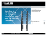
45° Side-Exiting Multmedia Panel
JPMT1024-ANG
45° Side-Exiting Multimedia Panel
Black Box Tech
Support: FREE! Live.
24/7. Tech support
the way it should be.
Direction of
IDC slot
BLACK BOX
®
Great tech support is just 30 seconds
away at 724-746-5500 or blackbox.com.
Angles ports
to the sides.
BLACK B
Helps to reduce stress on the ports.
Horizontal cable management is not required.
Figure 5. IDC slot position.
6. Secure the back cables with the supplied cable ties.
NOTE: Do not overtighten the cables.
7. Figure 6 shows a completed installation.
1. Specifications
Customer
Support
Information
Figure 6. Completed patch panel installation.
Order toll-free in the U.S.:
Call 877-877-BBOX
(outside U.S. call 1-724-746-5500)
FREE technical support
24 hours a day, 7 days a week:
Call 724-746-5500 or
fax 724-746-0746
Mailing address:
Black Box Corporation
1000 Park Drive
Lawrence, PA 15055-1018
Web site: www.blackbox.com
E-mail: [email protected]
© Copyright 2011. Black Box Corporation. All rights reserved.
Black Box and the Double Diamond logo are registered trademarks of
BB Technologies, Inc. Any other trademarks mentioned in this manual
are acknowledged to be the property of the trademark owners.
Size: Without rear base installed: 1.75”H (1U) x
19”W x 0.625”D (4.5 x 48.3 x 1.6 cm);
With rear base installed: 1.75”H (1U) x 19”W x
5”D (4.5 x 48.3 x 12.7 cm)
Weight: 1.5 lb. (0.7 kg)
2. Overview
2.1 Introduction
The 24-Port 45° Side-Exiting Multimedia Panel
angles ports to the sides, which helps reduce
stress on the ports and eliminates the need for
horizontal cable management. The rear of the
panel has an optional cable support bar that
provides support to horizontal cables accessing
the panel.
JPMT1024-ANG, rev. 1
JPMT1024-ANG
724-746-5500 | blackbox.com
Page 5
724-746-5500 | blackbox.com
Page 6
724-746-5500 | blackbox.com
45° Side-Exiting Multmedia Panel
45° Side-Exiting Multmedia Panel
45° Side-Exiting Multmedia Panel
2.2 What’s Included
2. Attach each side bracket to the matching end of the
bar accordiing to the same marking. See Figure 2.
4. Load the wired keystone jack into the patch panel.
Make sure the locking knob is locked first before
sliding in the keystone jack or support fitting. See
Figure 4.
Your package should include the following items.
If anything is missing or damaged, contact Black Box
Technical Support at 724-746-5500 or
[email protected].
mark “R”
Slide in
NOTE: Ports 1–6 and 13–18 share the same orientation, while ports 7–12 and 19–24 are placed
in opposite positions. Be sure to follow the
directions during installation.
• (1) 45° Side-Exiting Multimedia Patch Panel
• (2) side brackets
• (1) rear cable bar
NOTE: For best connector loading sequences, start
from the sides and install toward the center.
Slide in
• (24) cable ties
mark “L”
• (4) 10-32 screws
• (4) 12-24 screws
locking knob
Figure 2. Attaching the side bracket.
• This user’s manual
3. Snap the rear cable bar into the patch panel, as
shown in Figure 3.
3. Installation Steps
1. Mount the panel on a 19-inch rack, as shown in Figure 1.
latch
Figure 4. Loading the keystone jack or support fitting.
5. Make sure the IDC slot of the keystone jack faces
toward the center of the patch panel, as shown in
Figure 5.
Figure 3. Attaching the rear wire manager.
Figure 1. Mounting the panel on a rack.
JPMT1024-ANG
724-746-5500 | blackbox.com
Page 2
JPMT1024-ANG
724-746-5500 | blackbox.com
Page 3
JPMT1024-ANG
724-746-5500 | blackbox.com
Page 4