1
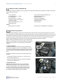
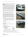
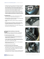
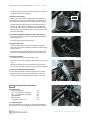
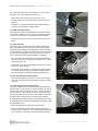
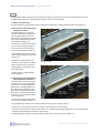
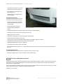
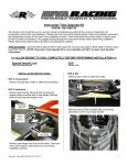
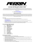
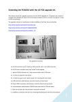
Installation Manual
Volvo C30 T5 Front Mount
Intercooler System
Volvo C30 T5 Intercooler System / Installation Manual
C
i
Contents
Important Information
i
Parts List
i
Required Tools and Materials
1
1.0 - Vehicle Preparation
1
2.0 - Removing and Trimming Front Fascia (Nose Section)
2
3.0 - Removing Factory Intercoolers and Tubes
3
4.0 - Installing New Intercooler
4
5.0 - Start Engine and Check Connections
6
6.0 - Trim and Install Front Fascia (Nose Section)
7
7.0 - Test Drive
8
!
Important Information
Congratulations on your purchase of the Bell Intercoolers Volvo C30 T5 Front Mount Intercooler System. The installation instructions in this manual will assist you in the complete process of installing your new intercooler. Please read through these instructions entirely before you begin the installation process. This will familiarize you with the process and alert you to any unique tools
or materials that may be required for successful installation.
This intercooler system is designed to be a bolt-in replacement for the factory components. Installation is not overly complex,
however, it is important to honestly evaluate your mechanical skills and determine if you are capable of performing the installation
or if you should have the system installed by a professional mechanic.
A modern internal combustion engine is a precise piece of equipment and while durable they can be severely damaged or destroyed through careless installation techniques.
To get the most performance from your new intercooler you will need to have an engine that is in a proper state of tune. Have any
problems with the engine or vehicle corrected prior to installing the intercooler.
Parts List
Part Name
Intercooler Assembly
M8 - 1.25 x 60mm Bolt - Hex Head
M8 Flat Washer
M5 - 0.8 x 20mm Bolt - Hex Head
M5 Flat Washer
Hose Clamp - T-Bolt 2.5”
Packet/Box
--
Parts - Bag 1
Parts - Bag 1
Parts - Bag 1
Parts - Bag 1
Parts - Bag 2
Qty
1
2
2
1
1
2
Bell Intercoolers, inc. © 2008 All rights reserved. C30-IMv1
Volvo C30 T5 Intercooler System / Installation Manual
1
Required Tools and Materials
To efficiently complete the installation of your intercooler you will need the following tools and materials, in addition to those parts
supplied with your intercooler.
Tools
• 1/4” Drive Ratchet
• 1/4” Drive Extensions - 3” Length
• 3/8” Drive Ratchet
• 3/8” Drive Extension - 3” Length
• Sockets 8 - 17 mm (1/4” or 3/8” Drive)
• 11 mm Deep Socket
• Wrenches (Open/Boxed) 8 - 17 mm
• Straight Edge Ruler
Materials
• WD-40, Motor Oil or Lubricant
1.0
• T20 and T30 Torx Bits and Suitable Driver
• Small Flat-head Screwdriver
• Phillips Screwdriver
• Hacksaw or Cutting Wheel
• Round and Flat File (optional)
• Vehicle Jack or Lift
• Jack Stands (x2)
• Grease Pencil or China Marker (non-permanent)
Vehicle Preparations
As with any vehicle modification project, the process will be easier, faster and safer for the engine, turbocharger and you if the engine compartment is thoroughly cleaned before you begin the project. Not only is a dirty engine compartment a mess to work in, but
a dirty engine compartment also offers the possibility that dirt and/or debris could be introduced into the intake tract of the engine.
A small stone or piece of debris falling into an open inlet tube can cause serious and expensive damage when the engine is
started, possibly damaging valves, cylinders and pistons. An easily avoidable, but expensive proposition.
While performing the installation keep the any open intake tubes (air
intake, etc.) covered with a clean rag and thoroughly check all tubes,
hoses and the intercooler for any foreign objects or debris before
installing.
1.1 Disconnect Battery
As a matter of safety you should disconnect the negative battery
terminal before beginning any work on this installation. This is done
to prevent any unintentional shorting of electrical components and to
remove the danger of accidentally energizing the starter motor with
a tool.
Battery
Cover
The battery is located in the right rear corner of the engine and is
covered.
• Locate battery and remove cover (Fig. 1.1). To remove cover
pull out on sides and lift front.
Figure 1.1
• Disconnect the negative terminal (Fig. 1.2) and move battery
cable away from negative post.
1.2 Jack Stands or Lift
Installation of this intercooler system can be accomplished
without placing the vehicle on a lift or jack stands. However,
you will find the installation process much easier with the car
elevated. If you will be lifting the car please consult Volvo service manual proper jack, jack stand and/or lift placement. Be
sure vehicle is securely positioned before proceeding.
Negative
Terminal
Figure 1.2
Bell Intercoolers, inc. © 2008 All rights reserved. C30-IMv1
Volvo C30 T5 Intercooler System / Installation Manual
2.0
2
Removing Front Fascia (Nose Section)
The first step in the installation will involve removal of the front fascia
(front nose section) of the vehicle (see Fig. 2.1). The front fascia of
the C30 is comprised of two pieces, an upper section and a lower
section, as shown in Figure 2.1. These two sections remaining joined
during the installation process and will not be separated. Attached to
the front fascia are the upper grill assembly, the front license plate
and mounting bracket, the driving light assemblies and driving light
grills (if so equipped). All of these pieces remain attached to the front
fascia when it is removed and only require that you disconnect one
wiring connector for each driving light assembly, one per side.
Front Fascia
(upper section)
Front Fascia
(lower section)
In addition to the front fascia there is a plastic splash guard positioned underneath the engine. This piece must be removed for installation.
Figure 2.1
To reduce the chance of damaging the vehicle paint on the front
fascia and the surrounding bodywork, we recommend you have
someone available to help when removing the front fascia.
Front Fascia
(upper section)
2.1 Remove Headlight Washer Covers (If so equipped)
If your vehicle is equipped with headlight washers there will be two
headlight washer covers, one per side, that will need to be removed.
This is actually the trickiest part of the entire installation process
though it only requires patience and some time to get the covers
off. It may be helpful to have someone to hold the covers in their extended position to allow you to see the clip mechanism that secures
the covers.
Front Fascia
(lower section)
• Carefully pull headlight washer covers away from the bodywork.
These covers are attached directly to the headlight washer mechanism, be careful not to twist or damage washer mechanism.
Splash
Guard
Figure 2.2
• Insert a small screwdriver into the clip on the underside of the
cover to release clip.
• Remove cover.
Fender Tab
• Repeat for opposite washer assembly.
2.2 Splash Guard
• Locate and remove the seven (7) T30 Torx fasteners securing the
splash guard.
• Remove splash guard.
2.3 Remove Front Fascia Fasteners
• The front fascia is secured by fasteners, plastic rivets and clips in
the following locations:
Passenger Fender Well
Fasteners (x5)
Driver Fender Well
Fasteners (x5)
Upper Radiator Bulkhead (across top)
Fasteners (x2),
Plastic Rivets (x5)
Lower Radiator Support (across bottom)
Tabs (x3)
1
2
3
4
5
Figure 2.3
• Remove the five (5) fasteners securing the front fascia in each fender well (see Fig. 2.3).
• Separate front of plastic fender lips from front fascia. Repeat for both sides.
• Using the T20 Torx bit remove the two (2) fasteners from the upper radiator bulkhead (see Fig. 2.4).
Bell Intercoolers, inc. © 2008 All rights reserved. C30-IMv1
Volvo C30 T5 Intercooler System / Installation Manual
• Carefully remove the five (5) plastic rivets securing the front fascia
to the upper radiator bulkhead (see Fig. 2.4). Please note, these
rivets are designed to be reused. Using a Phillips screwdriver
press the center section of the rivet down approximately 1/8”, until
you feel a click, when the rivet has released. Once released, you
may extract the rivet from the hole. Repeat for all rivets.
3
Upper Radiator
Bulkhead
• The lower section of the front fascia assembly is secured by three
plastic tabs inserted into the metal lower radiator support. Using a
screwdriver carefully release these tabs and pull the fascia assembly
forward to disengage. The front fascia is now ready to be removed.
2.4 Remove Fascia
• Starting at the upper rear corners of the front fascia, pull fascia
away from fender to release fender tab (see Fig. 2.3).
• Pull out the lower rear corners of the fascia to clear the lower edge
of the fender liners. Repeat for other side.
Figure 2.4
Driving Light
Assembly
• At upper radiator bulkhead, pull fascia forward to disengage from
fenders.
• Working evenly across fascia begin to pull fascia forward, away
from vehicle. Remember that you will need to disconnect the driving lights when the fascia does come free of the vehicle.
Harness
Connector
Location
• Disconnect driving light harnesses, one per side, and remove front
fascia (see Fig. 2.5, S40 model shown).
3.0
Removing Factory Intercooler
Figure 2.5
Intercooler
Air Guide
The C30 T5 utilizes a single intercooler design. The intercooler is
secured to the radiator assembly by two (2) T30 mounting bolts.
3.1 Remove Intercooler Air Guide
• In front of the intercooler is the intercooler air guide (see Fig. 3.1).
This plastic piece is attached to the radiator assembly two (2)
fasteners and three (3) plastic tabs.
Mounting
Tabs
• Locate and remove the two (2) T30 fasteners securing the intercooler air guide to the radiator assembly. These are located at the
upper corners of the intercooler air guide.
• Release three (3) tabs securing the bottom of the air guide to the
radiator assembly (see Fig. 3.1).
• Carefully remove intercooler air guide.
Figure 3.1
Intercooler
Inlet Hose
IAT Sensor
Harness
3.2 Remove Intercooler Inlet and Outlet Hoses
• Locate the intercooler inlet hose. This hose is located on the left
side (viewed from front of vehicle) of the intercooler (see Fig. 3.2).
• Loosen hose clamp securing intercooler inlet hose to intercooler
and disconnect hose from intercooler.
• Locate the intercooler outlet hose. This hose is located on the right
side (viewed from front of vehicle) of the intercooler (see Fig. 3.3).
Figure 3.2
Bell Intercoolers, inc. © 2008 All rights reserved. C30-IMv1
Volvo C30 T5 Intercooler System / Installation Manual
4
• Loosen hose clamp securing intercooler outlet hose to intercooler
and disconnect hose from intercooler.
Mounting
Bolt
3.3 Remove Hose Clamps
The factory hose clamps will be replaced with high-strength T-bolt
hose clamps for use with your new intercooler. You will need to remove the factory hose clamps prior to installing the new intercooler.
• Carefully remove factory hose clamps from intercooler inlet and
outlet hoses. These clamps are secured by a small metal barb
that grips the rubber hose. To release the barb carefully pry barb
away from hose. Once the barb is clear of the hose you may safely
remove the hose clamp.
Figure 3.3
3.4 Disconnect Intake Air Temperature (IAT) Sensor Harness
• Locate wiring harness connected to Intake Air Temperature (IAT)
sensor (see Fig. 3.2).
• Disconnect wiring harness from IAT sensor.
3.5 Remove Intercooler
• Locate and remove the two (2) T30 Torx fasteners securing the
intercooler to the radiator assembly, one fastener per left and right
side (see Fig. 3.3).
IAT
Sensor
• Intercooler is positioned with two plastic tabs at the lower corners.
Lift intercooler to disengage these tabs and remove intercooler.
3.6 Remove IAT Sensor
• Locate the IAT sensor on intercooler (see Fig. 3.4).
Figure 3.4
• Remove the one (1) T20 Torx fastener securing IAT sensor to intercooler.
• Carefully remove IAT sensor from intercooler. Sensor uses an oring, use care when removing the sensor so as to prevent damage.
Left Front
Crossmember
Mounting
Bolt
3.7 Remove Crossmember Mounting Bolts
Your new intercooler will be mounted using the front two (2) bolts
securing the radiator lower crossmember (See Figs. 3.5 and 3.6).
• Locate and remove indicated fasteners (see Figs. 3.5 and 3.6).
Figure 3.5
4.0
Installing New Intercooler
New Components
Intercooler Assembly
M5 - 0.8 x 20mm Bolt - Hex Head
M8 - 1.25 x 60mm Bolt - Hex Head
M5 Flat Washer
M8 Flat Washer
Hose Clamp - T-Bolt 2.5”
(x1)
(x1)
(x2)
(x1)
(x2)
(x2)
4.1 Install IAT Sensor
Prior to installing the new intercooler you will need to install the factory IAT sensor. This sensor installs in the same general position as
Right Front
Crossmember
Mounting
Bolt
Figure 3.6
Bell Intercoolers, inc. © 2008 All rights reserved. C30-IMv1
Volvo C30 T5 Intercooler System / Installation Manual
5
the on the factory intercooler. Refer to Figure 4.1 to ensure proper
orientation of the sensor relative to the intercooler.
• Apply a thin coating of motor oil to the IAT sensor o-ring.
• Carefully insert sensor into new intercooler. Position as shown in
Figure 4.1.
• Install M5- 0.8 x 20mm bolt and M5 washer (supplied with intercooler kit) to secure fastener. Tighten fastener.
4.2 Install T-Bolt Hose Clamps
The T-Bolt hose clamps must be installed prior to installing the intercooler. Refer to Figures 4.2 and 4.3 for proper orientation of clamps
to allow for correct clearance of the clamp bolts after installation.
IAT
Sensor
• Position hose clamps on intercooler inlet and outlet hoses. Do not
tighten.
4.3 Install Intercooler
The new intercooler will mount using new fasteners supplied with
the kit. These fasteners will install in place of the factory fasteners
securing the lower radiator crossmember that you removed in step
3.7. Be aware that you will be reconnecting the IAT sensor harness to
the intercooler after installation. Place wiring harness so it does not
become trapped or restricted during installation of intercooler.
Figure 4.1
• Move intercooler into position with mounting brackets located as
shown in Figures 4.4 and 4.5. Be sure hose clamps are in position
as described in step 4.2.
• Installed M8 - 1.25 x 60mm bolt and M8 washer at each mounting
point. Do not tighten fasteners.
• Position intercooler so there is a consistent gap of approximately
1/8” between the intercooler and the radiator assembly (see Fig.
4.6). When this gap is established, tighten mounting fasteners.
4.4 Reconnect IAT Sensor Wiring Harness
• Reconnect wiring harness to IAT sensor. Check to be sure wiring
harness is not restricted, kinked or pinched by intercooler. Adjust if
necessary.
Hose
Clamp
Figure 4.2
4.5 Install Intercooler Inlet and Outlet Hoses
For proper installation the hose clamps must be positioned behind
the hose bead as shown in Figure 4.7. Before installation of intercooler hoses mark all intercooler tubes with a line 1” in from the bead, as
shown in Figure 4.7. This will allow you be sure the clamp and hose
are properly positioned. There should be approximately 1/8” between
the edge of the hose and the edge of the clamp when installed.
Hose clamps should be tightened to the point where the hose cannot
be rotated against the metal tube. Overtightening can result in cutting
and damaging the hose.
• Slide intercooler inlet and outlet hoses onto intercooler.
• Position and tighten T-bolt hose clamps. Clamps should be positioned as shown in Figures 4.2 and 4.3. Be sure that the clamp bolts
do not contact any surrounding components. Adjust as necessary.
Hose
Clamp
Figure 4.3
Bell Intercoolers, inc. © 2008 All rights reserved. C30-IMv1
Volvo C30 T5 Intercooler System / Installation Manual
6
4.6 Recheck All Fasteners, Hose Clamps and Connections
Before proceeding, recheck all hose clamps for proper installation and clearance. Also recheck intercooler position (as per step
4.3) and all mounting fasteners. Recheck IAT sensor harness to be sure it is properly connected.
Intercooler
Mounting
Point
Left-Side Mounting Point
Figure 4.5
Intercooler
Mounting
Point
Right-Side Mounting Point
Intercooler
To Radiator
Gap
Figure 4.4
Figure 4.6
Hose
Clamp
Intercooler
Tube
Intercooler
Hose
1”
Retaining
Bead
Hose and Clamp Placement Diagram
5.0
Mark
Line
Figure 4.7
Start Engine and Check Connections
Before reinstalling the front fascia body work it is recommended that you remove the car from the jack stands or lift in order to
check engine operation and make sure all components are functioning properly. The car will be started, but not be driven at this
time, to determine that all components have been connected properly. Do not start car while on jack stands.
• Remove car from jack stands or lift.
• Reconnect battery.
• Start engine and allow engine to warm to operating temperature.
• Engine should idle and rev normally. If it does not, shut off engine and check for loose intercooler hose connections and disconnected IAT sensor wiring harness. Restart engine and check for normal idle and revs.
• Shut off engine and disconnect battery.
• Place car back on jack stands or lift to complete installation of front fascia bodywork.
Bell Intercoolers, inc. © 2008 All rights reserved. C30-IMv1
Volvo C30 T5 Intercooler System / Installation Manual
6.0
7
Trim and Install Front Fascia (Nose Section)
This step requires relatively easy trimming of the plastic and urethane components of the front fascia. All trimming can be easily
accomplished with a hacksaw or cutting wheel and cleaned up with a file and sand paper.
6.1 Remove Lower Grill Insert
The plastic grill insert in the lower grill opening is secured by nine plastic tabs. Carefully release tabs and remove grill insert.
6.2 Mark and Trim Lower Grill Opening
- Standard Trim Pattern
To provide adequate room for the new
intercooler it is necessary to trim the back
of the lower grill opening. For more aggressive cooling of the intercooler you may
wish to use the optional trimming pattern
shown in Step 6.3 (see Fig. 6.2).
Upper
Cut Line
(Upper Corner)
Mark 1/2”
From Back Edge
Upper Corner
Mark 1/2” From
Back Edge
• At each corner of bottom surface mark a
line 1/2” from back edge (see Fig. 6.1).
• At each corner of top surface mark a
line 1/2” from back edge (see Fig. 6.1).
Bottom
Cut Line
• Using a straight edge, mark line across
bottom surface connecting corner marks
(see Fig. 6.1).
• Repeat for top surface (see Fig. 6.1).
• Draw lines on side surfaces connecting
upper and lower corners (see Fig. 6.1).
(Lower Corner)
Mark 1/2”
From Back Edge
Standard Trim Pattern
D
Upper
Cut Line
• Carefully clean up cut edges with file
and/or sandpaper.
• At each corner of bottom surface mark a
line 1/2” from back edge (see Fig. 6.1).
Figure 6.1
C
• Using hacksaw or cutting wheel, carefully cut along lines.
6.3 Mark and Trim Lower Grill Opening
- High Temperature Trim Pattern
If you are planning on running your car at
track events or if you live in a hot climate
you may wish to use a more aggressive
trimming option for the grill opening. This
option removes more material from the
upper surface of the grill opening which allows more air to reach the upper portion of
the intercooler core. This trimming pattern
is shown in Figure 6.2.
(Lower Corner)
Mark 1/2”
From Back Edge
B
A
Bottom
Cut Line
(Lower Corner)
Mark 1/2”
From Back Edge
(Lower Corner)
Mark 1/2”
From Back Edge
Optional High Temperature Trim Pattern
Figure 6.2
• Using a straight edge, mark line across bottom surface connecting corner marks (see Fig. 6.1).
• At each corner of top surface, points A and D in Figure 6.2, mark a line 1/2” from back edge.
• As shown by points B and C in Figure 6.2 make a mark 1 1/2” from back edge of upper surface and 1 1/2” from the outer edge
of the upper surface. Repeat for both sides of upper surface.
• Using a straight edge, mark line connecting points A and B, B and C, C and D, as shown in Figure 6.2..
Bell Intercoolers, inc. © 2008 All rights reserved. C30-IMv1
Volvo C30 T5 Intercooler System / Installation Manual
8
• Draw lines on side surfaces connecting
upper and lower corners (see Fig. 6.1).
• Using hacksaw or cutting wheel, carefully cut along lines.
• Carefully clean up cut edges with file
and/or sandpaper.
6.4 Reinstall Front Fascia
Reinstall front fascia in reverse sequence
of removal process (see Step 2.0, pg 2).
• Position front fascia in front of car and
connect driving light wiring connectors
(if so equipped).
• Lift fascia and guide into position.
• Guide tabs below headlights into
position.
Trimmed Fascia Installed
Figure 6.3
• Guide upper fender tabs into position at each corner of the upper radiator bulkhead.
• Guide lower corners of fascia over fender liners (one per side).
• Gently press fascia into position.
• Guide three mounting tabs into position along lower radiator support.
• Press fender tabs into position on each side.
• Check fascia for proper fit and alignment against fenders and headlights. Adjust as necessary.
• Reinstall plastic rivets and fasteners across upper radiator bulkhead.
• Reinstall headlight washer covers (if so equipped).
• Clip fender lips into position, repeat for both sides.
• When installed, there should be a 1/8” - 1/4” gap between the intercooler surface and the back of the lower grill opening (see
Fig. 6.3).
6.4 Reinstall Splash Guard
Reinstall splash guard in reverse sequence of removal process (see Step 2.2, pg 2).
• Reinstall and tighten seven (7) T30 Torx fasteners securing splash guard.
7.0
Test Drive and System Checks
Testing should be done with the radio and AC/heat fan off and with all windows rolled up to allow you to properly hear the engine.
Allow engine to reach operating temperature and make certain the engine is running smoothly and normally, both at idle and
under load, prior to applying boost.
It is recommended that you recheck all intercooler tube connections after 500 miles to be sure all hoses and clamps are in proper
position. This is also the time to check for any potential clearance issues.
Installation is now complete.
Bell Intercoolers, inc. © 2008 All rights reserved. C30-IMv1