1
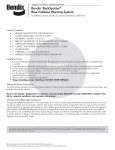
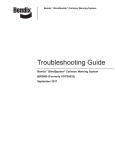
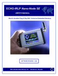
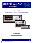
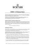
Bendix™ BackSpotter® Rear
Collision Warning System
User / Installation Guide
Bendix™ BackSpotter® Rear Collision Warning System
BW2768 (Formerly VODR0038)
May 2010
General Information
Warnings and Cautions
! WARNING
▲
Improper use of this system could lead to a serious accident. Read this
entire Operating Manual/Installation Guide before operating the Bendix™
BackSpotter® system. Pay particular attention to the safety messages below.
This manual should be used in conjunction with proper training.
Limitations of Collision Warning Systems
The Bendix™ BackSpotter® rear collision warning system is intended solely as an
aid for an alert and conscientious professional driver. It is not to be used or relied
upon to operate a vehicle. The system should be used in conjunction with rear view
mirrors and other instrumentation to maintain safe operation of the vehicle, ground
personnel, and adjacent property. A vehicle equipped with the Bendix™ BackSpotter®
system should be operated in the same safe manner as if the system were not
installed. The system is not a substitute for normal safe driving procedures. It will
not compensate for any driver impairment, such as drugs, alcohol, or fatigue. Should
the system become inoperative, it could jeopardize the safety or lives of those who
depend on the system for safety.
! WARNING
▲
The system will not sense objects if the sensor view is obstructed. Therefore,
do not place objects in front of the system sensor. Remove heavy buildups of
mud, dirt, ice, and other materials.
Proper alignment is critical to correct operation of the system.
Testing and inspection of the system in accordance with these instructions
and record of the results should be listed on the daily maintenance report.
The units on operating vehicles must be tested each day (see the “Testing
and Maintenance” section) prior to the vehicle’s operation. Results of this test
must be recorded in the maintenance log.
People operating this equipment MUST check for proper operation at the
beginning of every shift or safety inspection period.
i
General Information
! WARNING
▲
People’s lives depend on the proper installation of this product in
conformance with these instructions. It is necessary to read, understand, and
follow all instructions shipped with the product.
Failure to follow all safety precautions and instructions may result in property
damage, serious injury, or death.
The Bendix™ BackSpotter® system is intended for commercial use. Proper
installation of this system requires a good understanding of truck electrical
systems and procedures, along with proficiency in the installation.
Store these instructions in a safe place and refer to them when maintaining
and/or reinstalling the product.
ii
Table of Contents
Warnings and Cautions ..............................................................................................i
Federal Communications Commission ......................................................................1
Product Description ...................................................................................................2
System Operation .....................................................................................................5
Object Detection Capability .......................................................................................6
Installation.................................................................................................................8
Troubleshooting.......................................................................................................16
Specifications..........................................................................................................18
Limited Warranty .....................................................................................................19
Maintenance ...........................................................................................................20
iii
FCC Compliance
Federal Communications Commission
This device complies with Part 15 of the FCC (Federal Communications
Commission) rules. Operation is subject to the following two conditions: (1) This
device may not cause harmful interference and (2) this device must be able to
accept any interference received, including interference that may cause undesired
operation. Any interference that may be caused should be reported to the local FCC
field office or to the Federal Communications Commission; Enforcement Bureau;
445 12th Street S.W.; Room 7-C485; Washington, DC 20054.
! WARNING
▲
Any changes or modifications made by the user to this equipment that are not
expressly approved by Bendix Commercial Vehicle Systems LLC could void
the user’s authority to operate the equipment.
Every effort has been made to ensure the accuracy of all information in this
brochure. However, Bendix Commercial Vehicle Systems LLC makes no expressed
or implied warranty or representation based on the enclosed information. Errors or
omissions should be reported to: Bendix Commercial Vehicle Systems LLC, 901
Cleveland Street, Elyria, OH 44035 or 1-800-AIR-BRAKE (1-800-247-2725).
1
Operation
Product Description
The Bendix™ BackSpotter® system is a standalone vehicle radar system specifically
designed to alert a driver to objects behind the vehicle when the vehicle’s
transmission is placed in reverse. The system detects both moving and stationary
objects in a pre-defined coverage area and warns the driver via visual indicators and
audible warning tones. The system is designed to supplement other safety practices
and is not to be the sole method of collision avoidance.
The Bendix™ BackSpotter® system consists of three components:
1.
2.
3.
Rear sensor display mounted in the vehicle cab
Pulse-modulated rear mounted radar sensor
Interconnect harness
1
3
2
P2
2
Operation
Rear Sensor Display
The rear sensor display provides the driver with both visual and audible warnings
with the use of five (5) LED indicators and audible warning tones from the built in
speaker.
A volume control button on the front right of the rear sensor display allows the driver
to adjust the audible signal to three different audible levels (Low, Medium, and High).
An ambient light sensor on the front of the rear sensor display automatically dims
the intensity of the LEDs (light emitting diodes) in low light conditions.
Bendix™
BackSpotter®
In the event the system detects a failure, the rear sensor display will continuously
“flash” all five LED indicators, as well as an audible warning signal. See the
“Troubleshooting” section in this manual for more information.
3
Operation
Sensor Description
The radar sensor transmits and receives a low power 5.8 GHz radar signal. It
processes the returned signal to determine if an object is within the detection area
and reports this to the driver via the rear sensor display. The sensor’s fast response
time allows the driver to respond to dangerous situations immediately.
Bendix™
BackSpotter®
The sensor has a maximum detection zone depth of approximately 15 feet (5
meters) from the face of the sensor. When the radar sensor detects an object within
its detection zone, a signal is sent from the sensor to the rear sensor display to warn
the driver of a potential collision.
The table below shows how object detection is report to and displayed by the rear
sensor display from the sensor.
Condition
LED1
LED2
LED3
LED4
LED5
Speaker
Distance from Object*
No Object
Detected
off
off
off
off
off
off
More than 15'
Object
Detected
off
off
off
off
on
1Hz beep
Less than 15'
Object
Detected
off
off
off
on
on
1Hz beep
Object
Detected
off
off
on
on
on
2Hz beep
Object
Detected
off
on
on
on
on
4Hz beep
Object
Detected
on
on
on
on
on
8Hz beep
*Approximate distance
4
Less than 10'
Operation
System Operation
When the vehicle’s transmission is placed in reverse, the system will power up and
the rear sensor display will go through a quick self-test by momentarily flashing all
LEDs. When the system is operating correctly in an open field with no obstructions,
the green power LED will be the only light illuminated. If any or all of the detection
(yellow) LEDs are lit and a warning tone is heard, stop the vehicle and check for any
objects behind the vehicle being detected by the sensor.
Bendix™
BackSpotter®
5
Operation
Object Detection Capability
Because of the characteristics of radar, some objects may be detected at a
greater distance than others. Obstacle size, shape, and composition are all factors
determining when an object is detected.
The Bendix™ BackSpotter® system operates by transmitting a pulse of very low
power electromagnetic energy. Any energy that strikes an object reflects a certain
amount of this energy back to the sensor. This returned energy is measured to
determine the object’s presence and distance.
Reflected
signal returns
to sensor
Sensor's Reflected Energy
The amount of energy an object reflects is determined by several factors:
•
•
•
•
6
Size of the object.
Composition - A metal object reflects more energy than a non-metallic
object.
Scattering - A solid object reflects more energy than a non-solid object
such as wood, gravel, bushes, etc.
Angle - An object perpendicular to the sensor will reflect more energy than
an object at an angle.
Installation
Radar Sensor Location
The Radar Sensor mounting location is key to proper system operation. Ideally,
the Sensor should be centered on the rear of the vehicle at roughly 36" (1 m)
±12" (.3 m) from the ground, and should be a minimum of 5/16" out further than
other surfaces on the back of the vehicle (frame, bumper, box, etc.) to reduce the
possibility of interference with the sensor’s operation. The mounting location should
protect the sensor from impact when backing up to a dock, as well as, providing
an unobstructed view of the rear of the vehicle. The sensor face should also be
perpendicular to the ground.
Senso r
36"
! WARNING
▲
Before permanently installing the sensor to the vehicle, check to be sure
the area you selected to mount the sensor provides a clear detection zone.
Temporarily attach the sensor in the proposed mounting location, apply power
to the system, and verify nothing is being detected.
7
Installation
Sensor Installation
1.
2.
3.
4.
Select the appropriate sensor mounting location using the mounting
bracket supplied.
The sensor must be mounted with the “Bendix logo” parallel to the ground.
If mounting the sensor directly to the chassis or on a custom bracket,
use the sensor’s mounting holes as a template and score position marks
through the holes. Drill 1/4" (6 mm) holes centered at the marks.
Secure the sensor to the vehicle with the supplied 10-24 UNC button head
screws, washer, and nuts (or equivalent). Torque mounting screws 22
lbs. in. max.
Rear Sensor Display Installation
The rear sensor display should be mounted where it can be easily viewed and heard
by the operator while backing up the vehicle. Recommended mounting locations are
on the dashboard in front of the driver, or on the driver side windshield pillar.
The rear sensor display should not obstruct the driver’s view, or interfere with the
vehicle’s normal operation.
The rear sensor display comes equipped with a mounting bracket and hardware. The
rear sensor display is not watertight and should be mounted inside the vehicle cab.
Harness Installation
Use the corrugated loom provided in the installation kit to wrap the harness before
installing. Care should be taken to not route the interconnect harness next to heat
sources such as the engine exhaust, or areas that may expose the harness to
abrasion, strain or damage. Allow for a small service loop in the harness at the
sensor and secure the harness every one or two feet (30 to 60 mm) with tie wraps
or harness tape. Use the grommet provided to protect the harness when passing
through the cab wall (if required).
8
Installation
Harness Extension
The interconnect harness provided is 40 feet (14 meters) long, from sensor to
rear sensor display. Additional 20-foot (7 meter) extensions can be purchased for
applications requiring additional length (P/N 41365-100).
Radar Sensor Power Connection
Locate the vehicle’s reverse light power source and connect to the red power wire
on the sensor harness using 18 AWG wire. Connect the black ground wire of the
sensor harness to the vehicle ground.
The sensor should only have power when the transmission is in reverse.
Interconnection Table
Harness Lead
Red
Black
Vehicle Connection
Connect to Reverse Lamp Power (+12 v)
Connect to Vehicle Chassis Ground
To Rear Sensor Display
+ 12 V
Red
Black
To Rev
Lamp
BENDIX
9
Installation
Backup Alarm Control Feature
(optional harness required)
The Bendix™ BackSpotter® sensor has a built-in relay output that can control a
backup alarm, or any low current 12-volt device, whenever an object is detected.
This feature allows the backup alarm to remain silent when the vehicle is in reverse,
unless an object is present in the sensor’s detection zone.
The normally off output is tied to ground when the sensor is off, or no objects are
present. When the sensor is energized and detects an object, the built in relay
switches the output to +12 volts, providing power to the backup alarm via the fused
relay out harness lead.
An optional relay out harness is required to connect the backup alarm to the Bendix™
BackSpotter® sensor (P/N 41371-100). The relay out harness is equipped with an
inline 1-amp fuse, which protects the sensor from excess load current.
DO NOT USE A FUSE IN EXCESS OF 1 AMP.
To Rear Sensor Display
Red
+ 12 V
To Rev
Lamp
Black
1 amp fuse
Ground
10
BENDIX
Optional
Backup Alarm
Relay Harness
Installation
Initial System Power-Up
Once the Bendix™ BackSpotter® system is installed, power should be applied to test
correct system operation. Upon power-up, the driver display unit will go through a
self-test by flashing all LEDs. When the system is operating correctly in an open field
with no obstructions, the green power LED will be the only light illuminated. If any/
all of the detection (yellow) LEDs are lit, check for any obstruction which may be
detected by the sensor.
If the system is malfunctioning, all of the LEDs (yellow and green) will be flashing
and the buzzer will be sounding.
Function Test
1.
2.
3.
Before testing the sensor, make sure the sensor has a clear view of sight.
The recommended test area is 18 ft. (6 m) wide by 18 ft. (6 m) deep from
the rear of the vehicle.
Park the vehicle on a level surface. Block the wheels and keep the parking
brakes applied at all times.
Power up the Bendix™ BackSpotter® system by turning the vehicle
ignition to on (DO NOT START THE ENGINE) and placing the vehicle’s
transmission in reverse.
! WARNING
▲
If it is necessary to start the engine to place the transmission in reverse, turn
the engine off before testing the sensor. NEVER allow someone behind the
vehicle while the engine is running and the transmission is in reverse.
4.
5.
Verify the green LED on the rear sensor display is on and the unit
indicates NO objects are detected. If the display indicates object
detection, make sure the area around the sensor is clear and the sensor
mounting is appropriate.
Have an assistant test the sensor detection by holding a metallic test
target (minimum 10 in. x 10 in. [25 cm x 25 cm]) 6 ft. (2 m) from the sensor.
Keeping the target aimed directly at the sensor, move 6 ft. (2 m) to the left
and then 6 ft. (2 m) to the right, verifying that the sensor detects the target
all three locations. (See the illustration on the next page.)
11
Installation
6.
Finally, hold the test target 12 ft. (4 m) from the center of the vehicle rear,
aiming the target directly at the sensor. Verify the sensor can detect the
target at this location.
Note: The rear sensor display may not illuminate all 5 LEDs for a target 12 ft. (4 m)
away.
For maximum energy reflection when testing the sensor, keep the face of
the test target aimed directly at the sensor. The pattern below indicates the
sensor’s maximum detection capability and is for testing only. The sensor may
not detect all objects at these angles.
The sensor’s ability to detect depends on the composition of the target at its
ability to reflect pulse radar energy. The sensor may not detect humans, wood,
or other non-metallic objects within the sensor’s detection zone.
Target
6 ft (2 m)
Target
12 ft (4 m)
Target
6 ft (2 m)
Target
6 ft (2 m)
12
®
BackSpotter
0.25
5.36
5.24
1.38
3.53
B123456
Bendix
MADE IN USA
This product is protected under Patents:
US: 5345471, 5221600, 5757320, 5774091, 5517198
Mexico: 194188 Australia: 692921
Singapore: 37738, 42550
Patent(s) pending: European Community, Canada,
Japan, Korea, China, Singapore, Australia, Mexico.
FCC ID: OXZSTDPREVIEW
This device complies with part 15 of the FCC Rules.
Operation is subject to the following two conditions:
1) This device may not cause harmful interference.
2) This device must accept any interference received
including interference that may cause
undesired operations.
2.04
2.04
3.2
Installation
Diagrams
Radar Sensor
13
0.3
<10ft
14
REV
VOL
Bendix™
BackSpotter®
1.0
1.0
1.6
2.0
Installation
Rear Sensor Display
1
2
3
SENSOR
6
5
4
BACKSPOTTER
SENSOR
PWR
GND
COMM
ODU PWR
ODU GND
1
2
3
4
5
6
RED
BLACK
WHITE
DK GRN
BROWN
WIRING DIAGRAM
POWER
DK GRN
BROWN
WHITE
RED POWER
BLACK GROUND
GROUND
1
4
3
2
ODU PWR
OPERATOR
ODU GND
ODU COMM DISPLAY
UNIT
N/C
1
2
DISPLAY
4
3
Installation
Interconnect Harness
15
Troubleshooting
Troubleshooting
! WARNING
▲
The vehicle’s ignition must be on and the transmission in reverse for the
Bendix™ BackSpotter® system to power up. When testing and troubleshooting
the system, make sure (1) the ENGINE IS OFF, (2) the truck is in park on a level
surface, and (3) the parking brakes are properly set.
The Bendix™ BackSpotter® system has built-in self test diagnostics and will warn the
driver if the system detects a failure within the radar sensor. In the event the system
self-test detects a failure, all five of the LEDs on the rear sensor display will flash
along with a warning tone.
The following are typical symptoms and the possible causes:
All five LEDs on the rear sensor display unit are flashing.
•
The self-test has detected a failure within the radar sensor.
•
Inspect the radar sensor for proper mounting, debris buildup, or
damage.
•
Inspect the wiring harness for damage or corrosion.
The green power LED on the rear sensor display does not
illuminate when the vehicle is placed in reverse.
•
The Bendix™ BackSpotter® system is not powering up.
16
•
Check for power to the reverse lamp circuit.
•
Check the Bendix™ BackSpotter® harness power connections,
inspect for damage or corrosion.
•
Check for battery power at pin 1(+) and pin 2(-) at harness
connector J1 (sensor).
•
Check for system power (+5VDC) at pin 1(+) and pin 2(-) at
harness connector J2 (rear sensor display).
Troubleshooting
One or more warning LEDs remain on and a tone is heard, but
there are not objects behind the vehicle.
•
Inspect the radar sensor for proper mounting, debris buildup, or
damage.
•
Check for suspended objects or overhead clearances within a
15 feet radius of the radar sensor.
•
Inspect the radar sensor for proper mounting. Verify the sensor
is pointing outward from the vehicle in an open area with no
obstructions in its view.
•
If the sensor is detecting the ground, reposition the sensor
higher on the vehicle, or at a slight upward angle (2 to 5
degrees). The minimum recommended height from the ground
is 30 inches (75 mm).
The detection zone seems wider when detecting large objects
like other vehicles, than when detecting smaller objects or
people.
•
This is normal since vehicles have a greater radar cross
section than smaller objects, non-metallic objects, and people.
The interconnect harness to the rear sensor display is too
short.
•
Harness extensions can be purchased in 20-foot (7 meter)
increments (P/N 41365-100).
The backup alarm does not sound when used with the
(optional) relay out harness (P/N 41371-100).
•
Verify the positive lead on the backup alarm is hooked to the 1
amp fused relay out harness lead and the negative lead is tied
to the chassis ground.
•
Check the 1 amp fuse in the relay out harness. DO NOT use a
fuse larger than 1 amp.
17
Specifications
Specifications
Typical
Electronics
Solid state
Sealing
Encapsulated to protect from dust, moisture, and
vibration.
Operating Temperature
-40°F to +185°F (-40°C to +85°C)
Sensor
Pulsed RF transmitter at 5.8 GHz
Material
Weight
Dimensions
Mounting
Polycarbonate radome with aluminum back plate
1.75 lbs. (0.8 kg)
5.25" (13.3 cm) diameter x 1.25" (3.2 cm) deep
3 - 0.188 (4.8 mm) diameter mounting holes
Rear Sensor Display
Material
Weight
Dimensions
Mounting
18
Polycarbonate / ABS alloy
.25 lbs. (.11 kg)
1.00" (2.5 cm) height x 2.25" (5.7 cm) width x
2.00" (5.1 cm) depth
User dependent
Specifications
Electrical
Input Voltage
9 - 33 volts DC
Input Current
0.25 amp maximum (1 amp maximum)
Polarity
Polarity protected
Power Connection
2 - 18 AWG wires
Regulatory Compliance
Compliant with
FCC Part 15.249 (5725-5875 MHz)
FCC ID
OXZSTDPREVIEW
Manufacturer Limited Warranty
Bendix warranty limits and guidelines can be found in the Roadranger Warranty
Guide (TCWY-0900) and the Roadranger Warranty Manual (TCWY-0600). For
additional information visit www.roadranger.com or call 1-800-AIR-BRAKE
(1-800-247-2725).
19
Maintenance
Maintenance
The Bendix™ BackSpotter® is intended solely as an aid for an alert and conscientious
professional driver. A walk around test shall be performed every day to verify proper
function of the system and to familiarize the operator with the zone detection. More
frequent inspections should be performed when:
•
The vehicle is operating in a particularly dirty or harsh environment.
•
The operator has reason to suspect the system has been damaged.
Daily Maintenance Procedure
1.
2.
Clean the black sensor surface of any accumulation of dirt, mud, snow,
ice or debris.
Visually inspect the attached wiring and cable and verify that they are
properly secured, not chafing or dangling free where they could become
snagged and damaged. Inspect the sensor and driver display unit to verify
that they are securely attached to the vehicle.
! WARNING
▲
Vehicle brake must remain engaged to prevent injury.
3.
20
Test system for proper operation. (See the Installation section under
“Testing”.)
The Roadranger System features
Bendix brand foundation brakes.
®
®
BW2768 ©2010 Bendix Commercial Vehicle Systems LLC, a member of the Knorr-Bremse Group
All Rights Reserved • 05/10