1
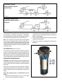
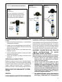
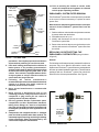
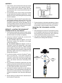
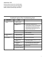
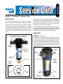
SD-08-187
®
Bendix® PuraGuard ® System Filter
DESCRIPTION
The PuraGuard ® system filter is used to assist the
production of purified compressed air on high air use vehicles.
The PuraGuard ® system filter consists of a filter element
mounted in a die cast aluminum housing. The sump
housing contains a drain valve for maintenance. For ease
of serviceability, all maintenance kits do not require removal
of the PuraGuard ® system filter from its mounting on the
vehicle.
ONE SUPPLY & ONE DELIVERY PORT
(SEE ARROW SYMBOL ON PURAGUARD®
SYSTEM FILTER TOP COVER FOR AIR FLOW)
MOUNTING
BRACKET
(2)
PURAGUARD®
SYSTEM FILTER
HEAD
High air use vehicles (e.g. transit vehicles) may require the
air compressor to exceed its normal duty cycle. The resulting
high compressor discharge temperatures can allow oil
aerosols to pass through the air dryer, condensing
downstream in air system components.
The PuraGuard ® system filter follows the air dryer in the system
and removes approximately 99% of oil aerosols. On vehicles
not using an air dryer, the PuraGuard ® system filter follows
the supply (“wet tank”) reservoir (see Figures 3 & 4).
OPERATION
GENERAL (See Figure 2)
Compressed air passes through the supply port of the
PuraGuard ® system filter and travels downward through the
center of the filter element. As the air passes through the
filter material, oil in liquid and aerosol form are removed and
collected in the sump. The air travels back up from the
sump, through the PuraGuard ® system filter delivery port
and into the air system.
DELIVERY
PORT
SUPPLY
PORT
SUMP
HOUSING
DRAIN VALVE
O-RING
FILTER
ELEMENT
HAS
O-RING
INCLUDED
EXTERIOR
VIEW
TOP
VIEW
SUPPLY
PORT
DELIVERY
PORT
SPRING
LOCATOR
FIGURE 1 - PURAGUARD ® SYSTEM FILTER
SPRING
FILTER
ELEMENT
DRAIN
PORT
FIGURE 2 - CUT-AWAY SHOWING AIR FLOW
1
PuraGuard ® System
Filter Installation System
with Air Dryer
Governor
Primary
Reservoir
PuraGuard ®
System Filter
Air
Compressor
Supply
Reservoir
Secondary
Reservoir
Air Dryer
FIGURE 3
PuraGuard® System Filter
Installation System without
Air Dryer
Governor
Primary
Reservoir
PuraGuard ®
System Filter
Air
Compressor
Supply
Reservoir
Secondary
Reservoir
FIGURE 4
The PuraGuard ® system filter has two female pipe thread
air connections: one supply, one delivery — identified by
their relationship to the arrow symbol showing air flow on
the PuraGuard ® system filter top cover (see Figure 1).
Note: The PuraGuard ® system filter is not recommended
to be used in conjunction with an alcohol evaporator or
injector. The PuraGuard ® system filter will remove the liquid
or aerosol alcohol introduced, defeat the purpose of the
evaporator/injector and require the sump to be drained more
often than normal.
2. Visually check for physical damage to the PuraGuard ®
system filter such as chaffed or broken air hoses and
broken or missing parts.
3. Check mounting bolts for tightness. Re-torque to vehicle
manufacturers guidelines.
4. Perform the Operation & Leakage Tests listed in this
publication.
FILTER BYPASS (refer to Figure 5)
If a situation occurs where the ability of the filter to allow air
to pass is impaired and causes a pressure difference of
approx. 20 p.s.i. between the air entering the filter element
and exiting, the filter will move downwards against the spring.
The air entering will then be able to bypass the filter element.
PREVENTIVE MAINTENANCE
Important: Review the warranty policy before performing
any intrusive maintenance procedures. An extended warranty
may be voided if intrusive maintenance is performed during
this period.
FILTER
MOVES
DOWNWARDS
AGAINST
SPRING
FORCE
Because no two vehicles operate under identical conditions,
maintenance intervals will vary. Experience is a valuable
guide in determining the best maintenance interval for a
vehicle.
Every 300 operating hours, or 8,000 miles or one (1)
month:
1. With the air system pressure at 0 p.s.i., use the drain
valve to collect contaminants for disposal.
2
FIGURE 5 - PURAGUARD ® SYSTEM FILTER BYPASS
FIGURE 6 - MAINTENANCE KITS AVAILABLE
5006788
MAINTENANCE KIT
5006789
REBUILD KIT
800691
RETROFIT KIT
This kit contains the PuraGuard ®
system filter assembly, brackets, and
drain valve. Some other fittings, etc.
are typically required for installation.
INCLUDED
IN KIT
INCLUDED
IN KIT
ALL PARTS
SHOWN ARE
INCLUDED
IN KIT
Every 3,600 operating hours, or 100,000 miles or one
(1) year:
PuraGuard ® system filter requires replacement or
maintenance, refer to Figure 7 to find the appropriate kit.
1. With the air system pressure at 0 p.s.i., drain collected
contaminants for disposal.
When rebuilding or replacing components of the PuraGuard ®
system filter use only genuine Bendix parts. For ease in
servicing, the PuraGuard ® system filter has been designed
so that the maintenance kits can be installed without
removing the PuraGuard ® system filter from the vehicle.
2. Visually check for physical damage to the PuraGuard ®
system filter such as chaffed or broken air hoses and
broken or missing parts.
3. Replace the filter element (see Maintenance Kits
available, Figure 6).
4. Check mounting bolts for tightness. Re-torque to vehicle
manufacturers guidelines.
5. Perform the Operation & Leakage Tests listed in this
publication.
OPERATION & LEAKAGE TESTS
Build the air system to governor cutout. Shut off the engine.
Using a soap solution, check all lines and fittings leading
to and from the PuraGuard ® system filter for leakage and
integrity. Repair any excessive leaks — exceeding a 1”
bubble in 5 seconds — before restoring vehicle to service.
REBUILDING THE PURAGUARD® SYSTEM
FILTER
GENERAL
If, after completing the routine operation and leakage tests,
it has been determined that one or more components of the
WARNING! PLEASE READ AND FOLLOW
THESE INSTRUCTIONS TO AVOID
PERSONAL INJURY OR DEATH:
When working on or around a vehicle, the following
general precautions should be observed at all times.
1. Park the vehicle on a level surface, apply the
parking brakes, and always block the wheels.
Always wear safety glasses.
2. Stop the engine and remove ignition key when
working under or around the vehicle. When
working in the engine compartment, the engine
should be shut off and the ignition key should be
removed. Where circumstances require that the
engine be in operation, EXTREME CAUTION should
be used to prevent personal injury resulting from
contact with moving, rotating, leaking, heated or
electrically charged components.
3. Do not attempt to install, remove, disassemble or
assemble a component until you have read and
thoroughly understand the recommended
3
10. Prior to returning the vehicle to service, make
certain all components and systems are restored
to their proper operating condition.
COVER (SHOWS
AIR FLOW
DIRECTION)
DELIVERY
PORT
SUPPLY
PORT
O-RING
FILTER
INTEGRATED
O-RING
PURAGUARD® SYSTEM FILTER REMOVAL
This PuraGuard ® system filter removal process is presented
in the event it becomes necessary to replace the entire
system filter.
Normal service and parts replacement does not require
removal of the PuraGuard® system filter from the
vehicle.
1. Park the vehicle on a level surface and prevent movement
by means other than the brakes.
2. Drain all reservoirs to 0 p.s.i.
3. Identify and disconnect the two air hoses from the
PuraGuard ® system filter.
FILTER
ELEMENT
SPRING
LOCATOR
SPRING
DRAIN
PORT
FIGURE 7 - CUT-AWAY VIEW
4.
5.
6.
7.
8.
9.
procedures. Use only the proper tools and observe
all precautions pertaining to use of those tools.
If the work is being performed on the vehicle’s air
brake system, or any auxiliary pressurized air
systems, make certain to drain the air pressure from
all reservoirs before beginning ANY work on the
vehicle. If the vehicle is equipped with an AD-IS™
air dryer system or a dryer reservoir module, be
sure to drain the purge reservoir.
Following
the
vehicle
manufacturer’s
recommended procedures, deactivate the electrical
system in a manner that safely removes all
electrical power from the vehicle.
Never exceed manufacturer’s recommended
pressures.
Never connect or disconnect a hose or line
containing pressure; it may whip. Never remove a
component or plug unless you are certain all
system pressure has been depleted.
Use only genuine Bendix ® replacement parts,
components and kits. Replacement hardware,
tubing, hose, fittings, etc. must be of equivalent
size, type and strength as original equipment and
be designed specifically for such applications and
systems.
Components with stripped threads or damaged
parts should be replaced rather than repaired. Do
not attempt repairs requiring machining or welding
unless specifically stated and approved by the
vehicle and component manufacturer.
4. Remove the two bolts that secure the brackets to the
vehicle, and remove the PuraGuard ® system filter from
the vehicle.
REPLACING OR RETROFITTING THE
PURAGUARD® SYSTEM FILTER (using kit shown
in figure 8)
General
The following retrofit instructions are presented for reference
purposes only since Bendix aftermarket retrofit and
replacement PuraGuard ® system filters are packaged with
the most up-to-date installation instructions. The instructions
packaged with the PuraGuard ® system filter should be
followed in lieu of those presented here. See Figure 8.
ALL PARTS
SHOWN ARE
INCLUDED
IN RETROFIT
KIT
FIGURE 8 - RETROFIT KIT
4
ASSEMBLY
1. Coat the drain valve threads with a liquid pipe thread
sealant. Install the drain valve using two wrenches one at the base of the PuraGuard ® system filter and
one on the drain valve, using a maximum final torque of
130-170 in. lbs.
2. The threaded top of the sump housing is pre-installed
into the head of the PuraGuard ® system filter. Check
that this connection is fully hand-tight before proceeding
with the installation.
3. The head cover of the PuraGuard ® system filter has an
arrow symbol showing the direction that the air must
be supplied into the head (see Figure 1). Align the
PuraGuard® system filter correctly (the label may not
be facing outwards) and then insert the four bolts through
the mounting bracket holes into the PuraGuard® system
filter head. Tighten to approx. 15 ft. lbs.
RETROFIT: LOCATING THE PURAGUARD®
SYSTEM FILTER ON THE VEHICLE
ELBOW
1/2 NPT HEX NIPPLE
FIGURE 9 - ELBOW FITTING IF NEEDED
7. To permit draining of collected contaminants, at least a
6 inch clearance below the PuraGuard ® system filter is
recommended. Nominal clearance above is required.
MOUNTING THE PURAGUARD® SYSTEM
FILTER
1. The PuraGuard ® system filter must be mounted vertically
(±5° ) and must not be exposed to direct wheel splash
(located behind axle mud flap is acceptable).
1. After positioning the PuraGuard ® system filter according
to the installation requirements, mark the position of
the mounting holes on the frame rail. Note: Check the
vehicle manual before drilling a frame member.
2. Locate the PuraGuard ® system filter as close to the
first (Supply) reservoir as possible.
2. Use vehicle manufacturer guidelines for mounting
hardware (use at least grade 5 hardware).
(a) For vehicles with air dryers, mount the
PuraGuard ® system filter upstream of the supply
reservoir (see Figure 3).
(b) For vehicles without air dryers, install the
PuraGuard ® system filter downstream of the supply
reservoir (wet tank) (see Figure 4). Both the primary
and secondary reservoirs will receive their air supply
from the discharge of the PuraGuard ® system filter and
depending original vehicle hose arrangement, extra
fittings may be required.
3. To minimize vibration, mount the PuraGuard ® system
filter on a frame rail. If the vehicle requires the
PuraGuard ® system filter to be directly mounted to the
reservoir, be sure to only use a high strength nipple
fitting. (See further notes under Connecting the Air
Hoses.)
ITEMS
INCLUDED IN
MAINTENANCE
KIT
ITEMS
INCLUDED IN
REBUILD
KIT
4. Do not locate the PuraGuard ® system filter near heat
producing components such as the vehicle exhaust and
provide adequate clearance from moving components
e.g. drive shaft, suspension, pitman arm, etc.
5. Locate the PuraGuard ® system filter on the vehicle so
that a minimum of 12 inches clearance horizontally (90°
minimum arc) to allow servicing. This will permit, for
example, a strap wrench to be used when replacing the
filter.
6. Be sure that there is sufficient room to attach hoses to
the PuraGuard ® system filter.
FIGURE 10 - MAINTENANCE KITS
5
CONNECTING THE AIR HOSES
Follow either Figure 4 or 5 for air hose arrangement.
1. The PuraGuard ® system filter supply and delivery ports
are 1/2-14 NPT. Install minimum 1/2 inch inside diameter
air hoses. When installing an elbow fitting use the fitting
arrangement shown in Figure 9, using a high strength
nipple and then an elbow fitting.
2. Hoses must be installed without tight turns that might
cause air flow restrictions. Note: Check that the hose
attachment agrees with the air flow arrow symbol (see
Figure 1). The label may not be facing forward when
installation is complete.
PURAGUARD ®
SYSTEM FILTER
HEAD
LARGE
O-RING
OPERATIONAL TEST
Build the air system to governor cutout. Shut off the engine.
Using a soap solution, check all hoses and fittings leading
to and from the PuraGuard ® system filter for leakage and
integrity. Repair any excessive leaks - exceeding a 1”
bubble in 5 seconds - before restoring vehicle to service.
MAINTENANCE KIT INSTALLATION
FILTER
ELEMENT
SPRING
KIT DESCRIPTION
The kits available allow either a filter element replacement
or major overhaul of the Bendix® PuraGuard ® system filter.
SPRING
LOCATOR
VEHICLE PREPARATION
1. Park the vehicle on a level surface and prevent movement
by means other than the brakes.
2. Drain all reservoirs to 0 p.s.i.
3. Drain the contents of the sump into a suitable container
for disposal and then re-close the drain valve.
SUMP
HOUSING
4. Using detergent and water, clean the exterior of the
PuraGuard ® system filter of road grime etc.
DISASSEMBLY AND CLEANING (see Figure 11)
1. Unscrew the sump housing of the PuraGuard ® system
filter. If necessary, use a strap wrench to assist this
process.
2. Remove and discard the filter and o-ring.
If only installing the maintenance kit, go to Inspection
section below.
FIGURE 11 - MAINTENANCE KIT COMPONENTS
3. Using long-nose pliers, carefully remove and discard
the spring and spring locator inside the sump housing.
If only installing the maintenance kit, go to item 4 below.
4. Using detergent and water or other suitable solvent, clean
inside the sump housing.
3. Using long-nose pliers, install the spring locator and
spring assembly into the sump (see Figure 11).
INSPECTION
4. Insert the replacement filter (guide lands uppermost)
into the sump with its base resting on the spring.
1. Inspect the PuraGuard® system filter for broken or
missing parts. Replace as necessary.
2. Inspect the drain valve for any build-up that could impair
its function. Clean as necessary.
ASSEMBLY (see Figure 11)
1. Install the replacement o-ring into the channel in the
head of the PuraGuard ® system filter.
6
2. Install the spring onto the spring locator.
5. Coat the threads of the sump housing using barium or
lithium grease. Sufficient torque to install the sump will
be produced by turning the housing by hand until fully
hand-tight. Take care not to damage the large
o-ring when installing the sump housing.
OPERATIONAL TEST
Build the air system to governor cutout. Shut off the engine.
Using a soap solution, check all hoses and fittings leading
to and from the PuraGuard® system filter for leakage and
integrity. Repair any excessive leaks - exceeding a 1”
bubble in 5 seconds - before restoring vehicle to service.
PuraGuard® System Filter Troubleshooting Chart
REMEDY
SYMPTOMS
CAUSE
1. More often than normal
(monthly) sump draining
required.
A. PuraGuard ® system filter
installed in incorrect
position in system.
A. See Figures 2 and 3 for correct installation.
B. Alcohol injector in
system.
B. The PuraGuard® system filter is not
recommended to be used in conjunction with an
alcohol evaporator or injector. [The PuraGuard ®
system filter will remove the liquid or aerosol
alcohol introduced, defeat the purpose of the
evaporator/injector and require the sump to be
drained more often than usual.]
C. Air dryer malfunction.
C. Check air dryer.
D. Compressor malfunction.
D. Check compressor.
2. Bypass feature not
working.
A. Supply and delivery air
connections reversed.
A. Reverse hose connections.
3. Oil in system.
A. Supply and delivery air
connections reversed.
A. Reverse hose connections.
B. Sump not drained
regularly.
B. Drain sump every 300 operating hours, or 8,000
miles or one (1) month.
C. Filter element
maintenance interval
exceeded.
C. Use a maintenance kit to replace PuraGuard ®
system filter element every 3600 operating
hours, or 100,000 miles or one (1) year.
D. Air dryer malfunction.
D. Check air dryer.
E. Compressor malfunction.
E. Check compressor.
7
8
BW2084 © 2004 Bendix Commercial Vehicle Systems LLC All rights reserved. 7/2004 Printed in U.S.A.