1
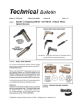
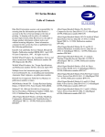
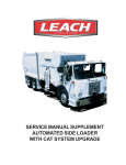
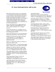
SD-13-4754
®
Bendix® WS-20™ AntiLock Wheel Speed Sensor
DEUTSCH 2 PIN
CONNECTOR
STRAIGHT WS-20™ SENSOR
PACKARD 2 PIN
CONNECTOR
90° WS-20™ SENSOR
FIGURE 1 - WS-20™ ANTILOCK WHEEL SPEED SENSORS
DESCRIPTION
™
The WS-20 wheel speed sensor is an electromagnetic
device used to obtain vehicle speed information for an antilock
controller. When the wheel rotates, the sensor and an exciter
(e.g. rotor or tone wheel) generate a simple AC signal. This
signal is sent to the controller, which analyzes the data and
commands the antilock system accordingly.
Specifically, the speed sensor consists of a coil, pole piece,
and magnet. The exciter is a steel ring or gear-like device
that has regularly spaced high and low spots called "teeth."
The sensor is mounted in a fixed position, while the exciter
is installed on a rotating member so that its "teeth" move, in
close proximity, past the tip of the sensor.
The WS-20™ wheel speed sensor is available in both straight
and right angle versions, to accommodate axle/wheel space
limitations. (See Figure 1.)
OPERATION
The sensor's magnet and pole piece form a magnetic field.
As an exciter tooth passes by the sensor, the magnetic
field is altered, which generates AC voltage in the sensor
coil. Each time an exciter tooth and its adjacent space move
past the tip of the sensor, an AC voltage "cycle" is generated.
The number of AC cycles per revolution of the vehicle's wheel
depends on the number of teeth in the exciter, which is
programmed into the antilock controller. Using the
programmed data, the controller can calculate "vehicle
speed" by analyzing the frequency of AC cycles sent by the
speed sensor. (The frequency of AC cycles is directly
proportional to wheel speed.)
AC voltage is also proportional to speed, but voltage is not
used to determine speed. It is only an indication of AC signal
strength. The amount of AC voltage generated by a specific
speed sensor depends on the distance, or "gap," between
the tip of the sensor and the surface of the exciter. Voltage
increases as the sensor gap decreases.
The WS-20™ wheel speed sensor is installed in a mounting
block that is affixed to the axle housing. (See Figure 2.) A
spring loaded retainer bushing provides a friction fit between
the mounting block bore and the WS-20™ sensor. The friction
fit allows the WS-20™ sensor to "slide" back and forth under
force but to retain its position when force is removed. This
1
feature allows the WS-20™ sensor to "self adjust" after it
has been installed in the mounting block and the wheel is
installed.
TECHNICAL INFORMATION
Electrical Connector-
2 Pin.
When the WS-20™ sensor is inserted all the way into the
mounting block and the wheel is installed on the axle, the
hub exciter contacts the sensor, which pushes the sensor
back. Also, normal bearing play will "bump" the sensor away
from the exciter. The combination of these two actions will
establish a running clearance or air gap between the sensor
and exciter.
Output Voltage-
With a 3,000 Ohm resistor across
the two sensor leads, output voltage
measured on a VOM = .800 VAC
Minimum at 42 Hz, or
approximately 5 mph.
Sensor Gap-
0 to .015 inch.
Sensor Body-
Formulated Epoxy; .628" Diameter.
Normal Resistance
Range at Room Temp- 2000-2500 ohms
PEAK TO PEAK
PREVENTIVE MAINTENANCE
1. Every 3 months; 25,000 miles; 900 operating hours; or
during the vehicle chassis lubrication interval, make the
visual inspections noted in "SERVICE CHECKS"
below.
LOW SPEED
2. Every 12 months; 100,000 miles; or 3600 operating hours,
perform the OPERATIONAL TEST in this manual.
PEAK TO PEAK
SERVICE CHECKS
Check all wiring and connectors. Make sure connections
are free from visible damage.
HIGH SPEED
FIGURE 2 - SPEED SENSOR VOLTAGE CYCLE OUTPUT
Examine the sensor. Make sure the sensor, mounting
bracket, and foundation brake components are not damaged.
Repair/replace as necessary.
WARNING! PLEASE READ AND FOLLOW
THESE INSTRUCTIONS TO AVOID
PERSONAL INJURY OR DEATH:
When working on or around a vehicle, the following
general precautions should be observed at all times.
ANTILOCK CONTROLLER
& RELAY
WS-20™ SPEED SENSORS
EXCITERS
FRONT WHEEL
REAR WHEELS
FIGURE 3 - TYPICAL ANTILOCK SYSTEM
2
1. Park the vehicle on a level surface, apply the
parking brakes, and always block the wheels.
Always wear safety glasses.
2. Stop the engine and remove ignition key when
working under or around the vehicle. When
working in the engine compartment, the engine
should be shut off and the ignition key should be
removed. Where circumstances require that the
engine be in operation, EXTREME CAUTION should
be used to prevent personal injury resulting from
contact with moving, rotating, leaking, heated or
electrically charged components.
3. Do not attempt to install, remove, disassemble or
assemble a component until you have read and
thoroughly understand the recommended
procedures. Use only the proper tools and observe
all precautions pertaining to use of those tools.
4. If the work is being performed on the vehicle’s air
brake system, or any auxiliary pressurized air
systems, make certain to drain the air pressure from
SPEED SENSOR
MOUNTING
BLOCK
100 TOOTH SPEED
SENSOR EXCITER
RING
100 TOOTH
EXCITER
MOUNTING
BLOCK
WS-20™ SPEED
SENSOR
BRAKE DRUM
MAX. GAP
(SENSOR TO EXCITER)
.015 INCHES
WS-20™ SPEED
SENSOR (90 DEG.)
HUB ASSEMBLY
FIGURE 4 - WS-20™ WHEEL SPEED SENSOR INSTALLATION
5.
6.
7.
8.
9.
10.
all reservoirs before beginning ANY work on the
vehicle. If the vehicle is equipped with an AD-IS™
air dryer system or a dryer reservoir module, be
sure to drain the purge reservoir.
Following
the
vehicle
manufacturer’s
recommended procedures, deactivate the electrical
system in a manner that safely removes all
electrical power from the vehicle.
Never exceed manufacturer’s recommended
pressures.
Never connect or disconnect a hose or line
containing pressure; it may whip. Never remove a
component or plug unless you are certain all
system pressure has been depleted.
Use only genuine Bendix ® replacement parts,
components and kits. Replacement hardware,
tubing, hose, fittings, etc. must be of equivalent
size, type and strength as original equipment and
be designed specifically for such applications and
systems.
Components with stripped threads or damaged
parts should be replaced rather than repaired. Do
not attempt repairs requiring machining or welding
unless specifically stated and approved by the
vehicle and component manufacturer.
Prior to returning the vehicle to service, make
certain all components and systems are restored
to their proper operating condition.
REMOVAL
1. Unplug the cable assembly connector from its lead.
Lift the lock tab and pull on the connector until it
disengages.
2. Gently pry the sensor and bushing from the mounting
block.
INSPECTION
Look for any visible damage to the sensor, cable assembly,
connector, mounting block, and foundation brake. Repair or
replace any damaged components. Make sure the block is
securely attached to the axle housing.
SENSOR INSTALLATION
1. For increased corrosion protection we recommend that
a high-temperature rated silicon- or lithium-based grease
be applied to the interior of the mounting block, the
sensor, and to a new clamping sleeve.
2. Gently push (DO NOT STRIKE) the sensor into the
mounting block hole until it bottoms out on the face of
the tone ring. Secure the cable lead wire to the knuckle/
axle housing 3-6 inches from the sensor.
3
3. Reconnect the connector to the sensor lead by plugging
it into the appropriate socket on the pigtail harness, and
pushing until the lock tab snaps into place.
NOTE: It is important for the wheel bearings to be adjusted
per the manufacturer's recommendations, to ensure
that the antilock function does not shut down as a
result of excessive wheel end play.
OPERATIONAL TESTING
To test sensor operation, one of two tests can be done.
TEST 1
Drive the vehicle in a safe area to a minimum speed of 15
mph. Be sure to apply the vehicle brakes several times.
Then stop the vehicle and check the LED display on the
Bendix controller. If the dash light is out and the sensor
LED(s) are not illuminated, the sensor is installed properly.
4
TEST 2
Disconnect the connector from the sensor's socket or from
the attached lead. Raise the vehicle wheel so it rotates easily.
Connect a volt-Ohm meter (set to read Volts AC) to the pins
on the sensor or lead and spin the wheel. Output voltage
should read greater than .800 AC. If the wheel is spun at 1
revolution per second (about 7mph) the reading should be
greater than 1.0 volts AC.
If the sensor fails to operate as described, check the wiring
from the controller to the sensor. Make sure all connectors
are properly and tightly installed. Check for frayed or
damaged wires and check and/or reset the sensor air gap
(distance from sensor tip to exciter ring) as described in
this manual. For additional troubleshooting information, see
the troubleshooting procedure for the specific antilock system
in use.
BW1662 © 2005 Bendix Commercial Vehicle Systems LLC All rights reserved. 1/2005 Printed in U.S.A.