1
SD-03-2202
Bendix® Double Check Valves
DELIVERY
SUPPLY
SUPPLY
SUPPLY
SUPPLY
DELIVERY
O-RING
DELIVERY
SHUTTLE
VALVE
CAP
VALVE
DISC
O-RING
CAP
SHUTTLE
GUIDE
VALVE
GUIDE
BODY
BODY
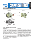
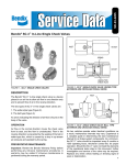
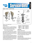
FIGURE 1 - DC-4™ DOUBLE CHECK VALVE (SHUTTLE TYPE)
FIGURE 2 - DOUBLE CHECK VALVE (DISC TYPE)
DESCRIPTION
OPERATION
Double check valves are used in an air brake system to
direct a flow of air into a common line from either of two
sources, whichever is at the higher pressure. They may be
used for directing air flow for specific functions or to select
the higher pressure of either of two sources of air as a
supply source.
As air under pressure enters either end of the double check
valve (inlet port) the moving shuttle or disc responds to the
pressure and seals the opposite port, assuming it is at a
lower pressure level than the other. The air flow continues
out the delivery port of the double check valve. The position
of the shuttle or disc will reverse if the pressure levels are
reversed. Double check valves are designed so that the
shuttle or disc can never impede the backflow of air in the
exhaust mode.
Bendix manufactures two types of double check valves:
shuttle and disc. Although the valves are somewhat different
physically, the same function is performed by both types.
The difference in the design of the two valves is that the
shuttle type has a movable shuttle to seal off the lower
pressure source, whereas the disc type has a movable disc.
Figure 3 (see page 2) illustrates a typical use of a double
check valve to control a given device, such as trailer brakes,
from either of two control sources.
Figure 4 (see page 2) illustrates a typical use of a double
check valve to supply air to a system or systems from either
of two separate sources, whichever is at the greater pressure
level. In this type of installation the pressure differential to
which the valve is subjected may under certain conditions
be minimal. It is therefore suggested that performance of
the double check valve will be optimized if it is mounted in
the horizontal position.
1
SERVICE CHECKS
Reservoir
OPERATING AND LEAKAGE TEST
Brake Valve
To Trailer
Brakes
Trailer Hand
Control Valve
Double
Check
Valve
FIGURE 3 - DOUBLE CHECK VALVE: CONTROL OF
SYSTEM FROM EITHER OF TWO CONTROL SOURCES
PP-7™
Valve
PP-1™
Valve
Trailer Supply
Spring Brake Control
Reservoir
Double Check
Valve
Reservoir
A. When the double check valve is used in conjunction with
a trailer control valve, the following operating and leakage
test can be made:
1. Apply and release foot brake valve and note that the
brakes apply and release on both tractor and trailer.
2. Apply and release the trailer control valve and note
that only the trailer brakes apply and release. With
trailer control valve applied check exhaust port of
foot brake valve for leakage with soap solution.
Permissible leakage is a 1” bubble in 5 seconds (100
sccm).
3. Apply and hold a full foot brake valve application.
Check exhaust port of trailer control valve for leakage
with soap solution. Permissible leakage is a 1”
bubble in 5 seconds (100 sccm). (Note: On some
vehicles, an exhaust line is connected to the exhaust
port and piped outside the cab in which case it may
be necessary to disconnect this line to make leakage
check.)
B. If the double check valve is to be bench tested or tested
on the vehicle, two separately controlled air supplies
must be connected to the inlet ports.
1. Install an accurate test gauge in the outlet port or in
a line from outlet port.
2. Apply and release air to one inlet port and note that
gauge registers application and release.
3. Repeat by applying and releasing air to other inlet
port.
4. Leakage check should be performed at inlet ports of
valve in the following manner:
a. Disconnect the line from one inlet port.
FIGURE 4 - DOUBLE CHECK VALVE: SYSTEM WITH TWO
SUPPLY SOURCES
b. Apply air to other inlet port and coat opposite
inlet port with soap solution. Permissible leakage
is a 1” bubble in 5 seconds (100 sccm).
PREVENTIVE MAINTENANCE
c. Repeat Step “b” applying air to other inlet port
while checking opposite inlet port for leakage.
Important: Review the Bendix Warranty Policy before
performing any intrusive maintenance procedures. A warranty
may be voided if intrusive maintenance is performed during
the warranty period.
No two vehicles operate under identical conditions; as a
result, maintenance intervals may vary. Experience is a
valuable guide in determining the best maintenance interval
for air brake system components. At a minimum, the DC-4™
valve should be inspected every 6 months or 1500 operating
hours, whichever comes first, for proper operation. Should
the DC-4™ valve not meet the elements of the operational
tests noted in this document, further investigation and service
of the valve may be required.
2
If the double check valve does not function as described or if
leakage is excessive, it is recommended that the valve be
repaired or replaced with genuine Bendix parts. The following
instructions should prove helpful:
DISASSEMBLY
1. Remove the end cap(s) from the valve.
2. Remove the grommets (if applicable).
3. Remove the shuttle and/or shuttle guide, disc and/or
disc guide (depending upon type of valve).
CLEANING AND INSPECTION
1. Clean all metal parts in mineral spirits and dry them
completely.
2. Inspect all parts for excessive wear or deterioration.
Inspect valve seats for nicks or burrs.
3. Inspect the bores of the valve housing for deep scuffing
or gouges.
Replace all parts that were discarded and any parts not
found to be serviceable during inspection, using only genuine
Bendix replacement parts.
ASSEMBLY
Before assembling the DC-4™ valve, lubricate all o-rings and
o-ring grooves with Bendix silicone lubricant (Pc. No. 291126)
or equivalent.
NOTE: When using pipe thread sealant during assembly
and installation, take particular care to prevent the
sealant from entering the valve itself. Apply the
sealant beginning with the second thread back from
the end.
1. Install the disc guide, disc and/or shuttle and shuttle
guide.
2. Coat all static seals such as o-rings, grommets, etc.
with BW 650M Silicone lubricant (BW 291126). It is not
necessary to lubricate shuttles or discs.
3. Install the grommets.
4. Install the end cap(s).
TESTING OF REBUILT DOUBLE CHECK VALVE
Perform operating and leakage tests as described in “Service
Checks” section.
GENERAL SAFETY GUIDELINES
contact with moving, rotating, leaking, heated or
electrically charged components.
3. Do not attempt to install, remove, disassemble or
assemble a component until you have read and
thoroughly understand the recommended
procedures. Use only the proper tools and observe
all precautions pertaining to use of those tools.
4. If the work is being performed on the vehicle’s air
brake system, or any auxiliary pressurized air
systems, make certain to drain the air pressure
from all reservoirs before beginning ANY work on
the vehicle. If the vehicle is equipped with an
AD-IS ® air dryer system or a dryer reservoir
module, be sure to drain the purge reservoir.
5. Following
the
vehicle
manufacturer’s
recommended procedures, deactivate the
electrical system in a manner that safely removes
all electrical power from the vehicle.
6. Never exceed manufacturer’s recommended
pressures.
7. Never connect or disconnect a hose or line
containing pressure; it may whip. Never remove a
component or plug unless you are certain all
system pressure has been depleted.
8. Use only genuine Bendix ® replacement parts,
components and kits. Replacement hardware,
tubing, hose, fittings, etc. must be of equivalent
size, type and strength as original equipment and
be designed specifically for such applications and
systems.
WARNING! PLEASE READ AND FOLLOW
THESE INSTRUCTIONS TO AVOID
PERSONAL INJURY OR DEATH:
9. Components with stripped threads or damaged
parts should be replaced rather than repaired. Do
not attempt repairs requiring machining or welding
unless specifically stated and approved by the
vehicle and component manufacturer.
When working on or around a vehicle, the
following general precautions should be
observed at all times.
10. Prior to returning the vehicle to service, make
certain all components and systems are restored
to their proper operating condition.
1. Park the vehicle on a level surface, apply the
parking brakes, and always block the wheels.
Always wear safety glasses.
11. For vehicles with Antilock Traction Control (ATC),
the ATC function must be disabled (ATC indicator
lamp should be ON) prior to performing any vehicle
maintenance where one or more wheels on a
drive axle are lifted off the ground and moving.
2. Stop the engine and remove ignition key when
working under or around the vehicle. When
working in the engine compartment, the engine
should be shut off and the ignition key should be
removed. Where circumstances require that the
engine be in operation, EXTREME CAUTION should
be used to prevent personal injury resulting from
3
4
BW1582 © 2007 Bendix Commercial Vehicle Systems LLC. All rights reserved. 3/2007 Printed in U.S.A.