1
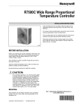
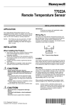
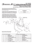
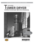
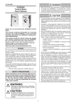
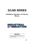
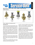
SD-03-3411
®
Bendix® MV-1™ Modutrol
VALVE A
VALVE B
5-3/8”
VALVE E
VALVE C
VALVE D
FIGURE 1 - MV-1™ MODUTROL
DESCRIPTION
®
™
The Bendix MV-1 modutrol assembly is an integrated air
control module designed for dash mounting in a truck/tractor.
The bodies for the modutrol assembly, as well as for the
“spool” inserts, are molded of a nonmetallic, noncorrosive
material. The assembly consists of three push-pull type
valves and two optional lever type valves. All valves utilize a
spool “insert,” which can be replaced from the front of the
assembly without removal of the assembly or connecting
air lines.
The three push-pull type valves provide the following functions:
2. Trailer service air supply.
3. System park.
4. Trailer park only.
5. Trailer recharge with tractor spring brakes applied.
Reference Figs. 1 & 5, valves V-1 and V-2 utilize identical
spool “inserts.” The functions of valves V-1 and V-2 are
essentially the same as the Bendix® PP-1™ control valve.
Valve V-3 utilizes a spool “insert” consisting of two valves; a
nonautomatic push-pull function similar to that of the Bendix®
PP-8™ valve, and a pilot operated three-way valve similar to
that of the Bendix® SV-1™ valve.
1. Tractor protection control.
1
The optional lever type valves housed in the auxiliary control
module consist of one or two lever type valves which may be
used to control any on/off type auxiliary devices such as a
sliding fifth wheel, inter-axle lockout, etc.
OPERATING MODE
V-1
The function as the lever type valves is similar to the Bendix®
TW-1™ control valve. One or both of the valves may be utilized
and, if required, a nonfunctional spool insert may be replaced
by a functional spool insert at any time. Port identification
for the push-pull module is shown on Fig. 6 and for the
auxiliary module on Fig. 9.
V-2
V-3
NORMAL RUN
BUTTON IN. DELIVERY
SUPPLIES BOTH SECTIONS
OF V-3 (PP-8™ AND SV-1™
VALVE).
BUTTON IN. DELIVERY TO
TRACTOR SPRING BRAKES
AND TO PILOT SECTION
OF PILOT VALVE (SV-1™).
TRACTOR BRAKES
RELEASED.
BUTTON OUT. UPPER
PORTION BLOCKS SUPPLY
AIR FROM V-1.
LOWER PILOT VALVE
(SV-1™) HELD OPEN BY
DELIVERY FROM V-2
PERMITTING V-3 DELIVERY
TO TRAILER SUPPLY LINE.
TRAILER BRAKES
RELEASED.
SYSTEM PARK
(POSSIBLY AUTOMATIC IF
SUPPLY PRESSURE IS
LOW.)
BUTTON IN. DELIVERY
SUPPLIES BOTH SECTIONS
OF V-3 (PP-8™ AND SV-1™
VALVE).
BUTTON OUT. EXHAUSTS
AIR FROM TRACTOR
SPRING BRAKES AND
FROM PILOT SECTION OF
PILOT VALVE (SV-1™).
TRACTOR BRAKES
APPLIED.
BUTTON OUT. UPPER
PORTION BLOCKS SUPPLY
AIR FROM V-1.
LOWER PILOT VALVE
(SV-1™) IN EXHAUST
POSITION EXHAUSTING AIR
FROM TRAILER SUPPLY
LINE. TRAILER BRAKES
APPLIED.
TRAILER PARK
(POSSIBLY AUTOMATIC IF
SUPPLY PRESSURE IS
LOW.)
BUTTON OUT. EXHAUSTS
ALL SUPPLY AIR FROM V-3
(PP-8™ AND SV-1™
VALVE).
BUTTON IN. DELIVERY TO
TRACTOR SPRING BRAKES
AND PILOT SECTION
(SV-1™). TRACTOR BRAKES
RELEASED.
BUTTON IN OR OUT. NO
SUPPLY AIR.
PILOT VALVE (SV-1™) IN
EXHAUST POSITION
VENTING TRAILER
SUPPLY LINE.
TRAILER BRAKES
APPLIED.
TRAILER RE-SUPPLY
BUTTON IN. DELIVERY
SUPPLIES BOTH SECTIONS
OF V-3 (PP-8™ AND SV-1™
VALVE).
BUTTON OUT. EXHAUST
AIR FROM TRACTOR
SPRING BRAKES AND
FROM PILOT SECTION
(SV-1™).
TRACTOR BRAKES
APPLIED.
BUTTON IN. SUPPLY AIR
FROM V-1 IS DELIVERED
THROUGH UPPER CAVITY
TO TRAILER SUPPLY LINE.
TRAILER BRAKES
RELEASED.
FIGURE 2 - MODUTROL OPERATING MODES
2
OPERATION
OPERATING AND LEAKAGE TESTS
The three push-pull control valves control all the required
functions of tractor spring brake control and trailer air
supply. The operating modes are detailed in Fig. 2 and in
the descriptive write-up which follows.
Prior to testing for leakage and function of the components
in either module, the knobs must first be removed from the
push-pull valves and then any panel cover plate or escutcheon
plates removed so that the top of the spool assemblies and
the retaining rings that hold the spools in place are visible.
INITIAL CHARGE
Without air pressure in any part of the system, valve buttons
V-1, V-2, and V-3 are out. When system pressure reaches
60 psi, valve buttons V-1 and V-3 may be pushed in and air
will be delivered through valve V-3 charging the trailer
system. The trailer parking brakes (whether spring or air
applied) will release; however, the tractor spring brakes
remain applied. Pushing valve button V-2 in will release
tractor spring brakes.
NORMAL RUN POSITION
With valve buttons V-1, V-2, in and V-3 out, air is being
supplied to the trailer, all parking brakes are released and
the system is in the normal run position.
ACTUATION OF TRAILER BRAKES ONLY
To actuate only the trailer brakes, valve button V-1 is pulled
out. This action exhausts the air supply from the trailer
supply line, causing the tractor protection valve to close.
Typical use of this mode would be to apply trailer brakes
before uncoupling. This mode would be used during a tractor
“bob-tail” operation.
MANUAL SYSTEM PARK
To apply the parking brakes on both tractor and trailer, valve
button V-2 is pulled out.
NOTE: If the trailer is not equipped with spring brakes
(pre-121), it is desirable to release the trailer
emergency application and provide a “demonstrated
park” (proven holding ability via tractor spring brakes
only). This may be done by positioning valve button
V-1 “IN,” V-2 button “OUT,” and pushing button V-3
“IN.” This action recharges the trailer supply line,
releases the trailer brakes and allows the tractor
spring brakes to demonstrate their ability to hold
both the tractor and trailer in a parked position.
AUTOMATIC SYSTEM PARK
If the supply or delivery pressure for the push-pull module
is reduced, either valve buttons, V-1 or V-2, or both will pop
out automatically when the supply pressure is between 35-45
psi. When button V-1 pops out, the trailer supply line will
vent to atmosphere, applying trailer brakes; should button
V-2 pop out, the tractor spring brakes will also apply as well
as the trailer.
For an operational test of the push-pull module, a test gauge
should be connected to a tractor spring brake line and one
to the trailer supply hose.
Function of the push-pull valves may then be checked per
the chart, Fig. 3.
PUSH-PULL MODULE OPERATIONAL TEST
AIR DELIVERY AIR DELIVERY
VALVE
TO TRACTOR TO TRAILER
SUPPLY
POSITION
SPRING
SUPPLY
PRESSURE V-1 V-2 V-3
BRAKES
HOSE
100 PSI
IN OUT OUT
ZERO
ZERO
IN
IN OUT
100 PSI
100 PSI
IN OUT IN
ZERO
100 PSI
OUT IN* OUT
100 PSI
ZERO
100 PSI
IN
IN OUT
100 PSI
100 PSI
REDUCING
TO
35-45 PSI
OUT OUT OUT
ZERO
ZERO
*When V-2 is pushed IN, V-3 should pop OUT.
FIGURE 3
PUSH-PULL MODULE LEAKAGE CHART
100 PSI SUPPLY PRESSURE FOR ALL TESTS
VALVE
POSITION
V-1 V-2 V-3
Leakage Symptoms Correction
OUT OUT OUT Valve V-1 at S-1
Replace spool
(Around Stem)
assembly in V-1
Valve V-2 at S-2
Replace spool
(Around Stem)
assembly in V-2
OUT OUT OUT Valve V-1 at S-3
Replace spool
assembly in V-1
Valve V-2 at S-4
Replace spool
assembly in V-2
Exhaust Port P-6
Replace spool in
V-1 or V-2 as
required
IN OUT OUT Valve V-3 at S-5
Replace spool in
V-3
Valve V-3 at S-6
Replace spool in
V-3
Exhaust Port P-6
Replace spool in
V-1
or V-3 as required
OUT IN
OUT Exhaust Port P-6
Replace spool in
V-2
or V-3 as required
IN OUT IN
Exhaust Port P-6
Replace spool
assembly in V-1
or V-3
FIGURE 4
3
VALVE V-1
S-1
VALVE V-2
S-2
S-3
VALVE V-3
S-4
S-6
S-5
P-6
FIGURE 5 - PUSH-PULL VALVE LEAKAGE KEY
AUXILIARY MODULE LEAKAGE CHART
P-2
P-3 (SUPPLY)
OPERATING MODE (SUPPLY CHARGED TO 100 PSI)
VALVE
POSITION
T-1
T-2
OFF
OFF
Leakage
Symptoms
S-1
S-4
Exhaust Hole
Exhaust Hole
P-5
(DELIVERY TO
TRAILER AIR
SUPPLY
ON
P-6 (EXHAUST)
FIGURE 6 - TRACTOR SPRING BRAKE DELIVERY
4
ON
Exhaust Hole
Exhaust Hole
FIGURE 7
Correction
Replace
in T-1
Replace
in T-2
P-7 Replace
in T-1
P-8 Replace
in T-2
P-7 Replace
in T-1
P-8 Replace
in T-2
spool assy.
spool assy.
spool assy.
spool assy.
spool assy.
spool assy.
VALVE T-1
VALVE T-2
S-1
P-7
S-4
P-8
FIGURE 8
T-2 DELIVERY (P-3)
SUPPLY
P-1
P-2
P-5
T-1 DELIVERY
(P-4)
P-6
SUPPLY
FIGURE 9
5
Leakage of the push-pull valves may then be checked per
the chart shown on Fig. 4 and the key shown on Fig. 5.
A normal supply pressure of 100 psi at supply port P-3 is
assumed for these leakage tests. Leakage may be checked
by a soap solution.
NOTE: Take care in not allowing excessive soap solution
in valve.
The auxiliary on/off module may be checked for leakage per
chart shown on Fig. 7 and key 8, again assuming a 100 psi
supply pressure at any one of the four supply ports.
REMOVING AND REPLACING SPOOL INSERT
ASSEMBLY
Release all air pressure from the supply to the module.
Remove the retaining ring from the cavity involved, pull out
the spool assembly and replace with a new spool. The spool
will normally be packaged with pre-lubricated o-rings;
however, should additional lubricant be required,
BW-650M (Dow Corning 55-M) should be used (Bendix
piece number 291126).
The push-pull assemblies may be installed without regard
to radial orientation; however, the lever type on/off spool
assemblies must be installed with the operating lever in either
the horizontal or vertical position.
NOTE: The segment on the bottom of the spool must match
the appropriate notch in the bottom of the cavity. If
the spool is not properly located, the retaining ring
cannot be installed.
If leakage persists after changing spool assemblies, the body
casting may be at fault. Check threaded bosses for cracks.
The interior walls should be examined carefully for scratches
or grooves, which would prevent static o-rings on the spool
assembly from sealing. If this condition persists, the complete
module should be replaced with genuine Bendix parts.
Replacement spool assemblies or nonfunctional plugs are
available at authorized Bendix parts outlets.
WARNING! PLEASE READ AND FOLLOW
THESE INSTRUCTIONS TO AVOID
PERSONAL INJURY OR DEATH:
When working on or around a vehicle, the following
general precautions should be observed at all times.
1. Park the vehicle on a level surface, apply the
parking brakes, and always block the wheels.
Always wear safety glasses.
2. Stop the engine and remove ignition key when
working under or around the vehicle. When
working in the engine compartment, the engine
should be shut off and the ignition key should be
removed. Where circumstances require that the
engine be in operation, EXTREME CAUTION should
be used to prevent personal injury resulting from
contact with moving, rotating, leaking, heated or
electrically charged components.
3. Do not attempt to install, remove, disassemble or
assemble a component until you have read and
thoroughly understand the recommended
procedures. Use only the proper tools and observe
all precautions pertaining to use of those tools.
4. If the work is being performed on the vehicle’s air
brake system, or any auxiliary pressurized air
systems, make certain to drain the air pressure from
all reservoirs before beginning ANY work on the
vehicle. If the vehicle is equipped with an AD-IS™
air dryer system or a dryer reservoir module, be
sure to drain the purge reservoir.
5. Following
the
vehicle
manufacturer’s
recommended procedures, deactivate the electrical
system in a manner that safely removes all
electrical power from the vehicle.
6. Never exceed manufacturer’s recommended
pressures.
7. Never connect or disconnect a hose or line
containing pressure; it may whip. Never remove a
component or plug unless you are certain all
system pressure has been depleted.
8. Use only genuine Bendix ® replacement parts,
components and kits. Replacement hardware,
tubing, hose, fittings, etc. must be of equivalent
size, type and strength as original equipment and
be designed specifically for such applications and
systems.
9. Components with stripped threads or damaged
parts should be replaced rather than repaired. Do
not attempt repairs requiring machining or welding
unless specifically stated and approved by the
vehicle and component manufacturer.
10. Prior to returning the vehicle to service, make
certain all components and systems are restored
to their proper operating condition.
BW1443 © 2004 Bendix Commercial Vehicle Systems LLC. All rights reserved. 3/2004 Printed in U.S.A.
6