1
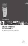
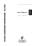
LARGE-DIAPHRAGM STUDIO CONDENSER MICROPHONE
User’s Manual
Version 1.0
March 2006
C-3
LARGE-DIAPHRAGM STUDIO CONDENSER MICROPHONE C-3
1. SAFETY PRECAUTIONS
Please read all safety precautions and operating instructions
before attempting to operate the unit. Keep all safety precautions
and operating instructions for future reference.
Water and moisture:
Condenser microphones are extremely moisture-sensitive. Never
use your microphone in close proximity to water (e.g. bath tubs,
wash basins, sinks, washing machines, pools, etc.).
Power supply:
Always use the power supply specified in the operating
instructions.
Damage:
Take care not to drop your microphone as this can lead to severe
damage. BEHRINGER assumes no liability for any damage caused
by the user.
Service and care:
After each use, wipe the microphone down with a soft cloth and
place it back into its protective casing (included with the
microphone).
Caution:
Never dismount the screen holding the capsule, as this can
damage the microphone! Never try to modify the printed circuit
board inside your C-3! This can lead to microphone damage that
cannot be repaired. Any such attempt will void the warranty.
2. POWER SUPPLY
Your condenser mic C-3 needs a phantom power supply
(+48 V). If your C-3 is connected to a microphone preamp and
supplied with phantom power, the LED on the microphone lights
up. BEHRINGER assumes no liability for any damage caused by
a defective phantom power supply. Always mute the sound
reinforcement system before you switch on the phantom power
supply.
3. DIRECTIVITY
Your C-3 is a large-diaphragm microphone featuring a double membrane. This allows you to choose between three different pickup
patterns - cardioid, omnidirectional and figure eight. Make your selection using the switch located at the back of your microphone.
2
3. DIRECTIVITY
LARGE-DIAPHRAGM STUDIO CONDENSER MICROPHONE C-3
3.1 Cardioid
Microphones with this polar pattern (switch position: middle, )
are most sensitive to sound coming from in front of the
microphone, and also to a lesser extent from the sides. Sound
coming from behind the microphone will be greatly attenuated.
This makes the cardioid polar pattern most suitable for recording
individual instruments or vocals within a group.
3.2 Figure Eight
Microphones featuring the figure eight polar pattern (switch
position: left, ) are most sensitive to sound coming from either
directly in front of or directly behind the microphone. Sound
coming from either side or above / below is greatly attenuated.
This polar pattern is perfectly suited as a reporter mic for two
speakers. This pattern can also allow you to create a natural
reverb or delay effect. This is achieved by placing the
microphone between the sound source and a wall. The direct
sound reaches the „front“ membrane first, the reflected sound
reaches the „rear“ membrane a short time later. You can adjust
the delay / reverb time by changing the distance from the mic to
the wall.
3.3 Omnidirectional
If you use the C-3 with the omnidirectional polar pattern selected
(switch position: right, ), the microphone is equally susceptible
to sound coming from all directions. This polar characteristic is
particularly well suited to sessions in which a natural sounding
recording is sought, or when several sound sources surround
the C-3.
4. LOW CUT-FILTER AND SIGNAL LEVEL ATTENUATION
The low cut filter is activated via the left switch located at the
front of your C-3 (switch position: left,
). Disruptive, lowfrequency sounds such as subsonic noise, snapping and wind
sounds can be filtered out. When the low cut filter is active,
when recording a voice from a close distance, you get an almost
entirely linear frequency response.
The switch located on the front right side of your C-3 activates
the -10 dB signal level attenuation (switch position: right, -10 dB).
This function is particularly recommended when recording impulse sound sources with high sound pressure (e.g. a bass
drum).
4. LOW CUT-FILTER AND SIGNAL LEVEL ATTENUATION
3
LARGE-DIAPHRAGM STUDIO CONDENSER MICROPHONE C-3
5. MICROPHONE INSTALLATION
A holder is screwed onto your microphone, allowing you to attach it to mic
stands with a 3/8" or 5/8" thread. An
adapter has been included. First
dismantle the microphone
from the
stand mount adapter
by detaching
at
the fine-thread shoulder screw
the bottom end of the microphone. Fasten the adapter onto the microphone
stand, place the microphone into it and
tighten the screw again.
Basically, the microphone in the stand
mount adapter should stand upright and
face the sound source at a right angle.
The angle of the microphone to the
sound source influences the sound of
Fig. 5.1: Attaching
the recording; therefore, experiment the microphone stand
with different positions until you achieve
the desired sound. To this end, you can rotate the mic in the
stand mount adapter by loosening the screw somewhat and
tightening it again.
If necessary, you can bend the microphone out of its vertical
position by using the hinge on the microphone stand.
Please make sure to handle the microphone shaft
with attention and care to avoid damaging the
screw thread. In no situation should you ever
apply excessive force.
Of course, you can detach the C-3 from the stand mount adapter
and attach it to a commercially available suspension mount.
6. AUDIO CONNECTION
Use a balanced XLR microphone cable with the following pin
assignment: pin 1 = shielding; pin 2 = +; pin 3 = -. Since your C-3
features gold-plated contact points throughout, we recommend
that you use only microphone cables with gold-plated connectors.
4
6. AUDIO CONNECTION
LARGE-DIAPHRAGM STUDIO CONDENSER MICROPHONE C-3
7. LEVEL SETTING/ADJUSTING THE BASIC SOUND
Adjust the gain control in the microphone channel of your mixing
console so that the peak LED lights up only occasionally or never
at all. The EQ controls in the microphone channel should be set to
mid-travel position to start with; low cut filter and signal level
attenunation should be switched off. To get the sound you want,
try changing the mic position relative to the sound source or
even move the microphone around in the recording room of your
studio. Adjusting the angle at which walls face the sound source
can also be helpful. Only when the desired basic sound has
been achieved, should you start to use equalizers and signal
processors, if any at all (remember: less is often more!)
Due to the extremely linear frequency response and the high
sonic resolution of your C-3, there is no need for high-frequency
“EQing” that can heavily influence the signal and unnecessarily
increase the noise level. The C-3 provides that much-desired
transparency which often gets lost during recording and mixing.
8. WARRANTY
The currently applicable warranty conditions can
be
found
on
our
website
at
http://
www.behringer.com; alternatively via fax +49 2154
9206 4199 or telephone +49 2154 9206 4166.
9. SPECIFICATIONS
Transducer type:
Polar pattern:
Connection:
Open circuit sensitivity:
Frequency response:
Max. SPL (< 0,5% THD @ 1 kHz):
Equivalent noise level:
Dynamic range:
Rated Impedance
Supply voltage:
Supply current:
Dimensions:
Weight:
condenser, 16 mm
cardioid, figure 8, omni
gold-plated balanced
XLR connector
-40 dBV/pa (10 mV/pa)
40 Hz - 18 kHz
142 dB
23 dBA (IEC 651)
119 dB
350 Ω
+48 V
7.0 mA
∅ shaft: 54 mm,
length: 180 mm
approx. 0.45 kg
9. SPECIFICATIONS
5
LARGE-DIAPHRAGM STUDIO CONDENSER MICROPHONE C-3
0º
5
10
15
20
25
dB
45º
90º
45º
90º
135º
135º
180º
Super Cardioid
Figure 8
Omni
Polar pattern
dB
Cardioid
Figure 3
Omni
Low Cut
-10dB
10
0
-10
-20
20
50
100
200
500
1000
2000
5000
10000
20000 Hz
Frequency response
BEHRINGER is constantly striving to maintain the highest professional standards. As a result
of these efforts, modifications may be made from time to time to existing products without prior
notice. Specifications and appearance may differ from those listed or illustrated.
Technical specifications and appearance subject to change without notice. The information
contained herein is correct at the time of printing. The names of companies, institutions or
publications pictured or mentioned and their respective logos are registered trademarks of
their respective owners. Their use neither constitutes a claim of the trademarks by BEHRINGER®
nor affiliation of the trademark owners with BEHRINGER®. BEHRINGER® accepts no liability
for any loss which may be suffered by any person who relies either wholly or in part upon any
description, photograph or statement contained herein. Colours and specification may vary
slightly from product. Products are sold through our authorised dealers only. Distributors and
dealers are not agents of BEHRINGER® and have absolutely no authority to bind BEHRINGER®
by any express or implied undertaking or representation. No part of this manual may be reproduced
or transmitted in any form or by any means, electronic or mechanical, including photocopying
and recording of any kind, for any purpose, without the express written permission of BEHRINGER
Spezielle Studiotechnik GmbH. BEHRINGER® is a registered trademark.
ALL RIGHTS RESERVED. © 2006
BEHRINGER Spezielle Studiotechnik GmbH,
Hanns-Martin-Schleyer-Str. 36-38,
47877 Willich-Münchheide II, Germany.
Tel. +49 2154 9206 0, Fax +49 2154 9206 4903
6
9. SPECIFICATIONS