1
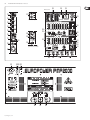
User Manual EUROPOWER PMP2000 800-Watt 14-Channel Powered Mixer with Multi-FX Processor behringer.com 2 EUROPOWER PMP2000 User Manual Table of Contents Thank you........................................................................ 2 Important Safety Instructions....................................... 3 Legal Disclaimer.............................................................. 3 Limited Warranty............................................................ 3 1. Introduction................................................................ 6 1.1 Before you get started....................................................... 6 1.1.1 Shipment........................................................................... 6 1.1.2 Initial operation.............................................................. 6 1.1.3 Online registration........................................................ 6 2. Control Elements........................................................ 6 2.1 Front panel............................................................................. 6 2.2 Rear panel ............................................................................. 7 3. Effects Processor......................................................... 8 4. Installation.................................................................. 8 4.1 Mains voltage........................................................................ 8 4.2 Mains connection................................................................ 8 4.3 Audio connections.............................................................. 8 4.4 Loudspeaker connections................................................ 9 5. Wiring Examples......................................................... 9 6. Specifications............................................................ 11 Thank you Congratulations! With the PMP2000 you have acquired a state-of-the-art 14-channel power mixer that sets new standards. Right from the start, our goal has been to design a revolutionary device that can be used for a great variety of applications. And indeed, this overwhelming power mixer gives you plenty of functionality and a broad range of connection and expansion options. behringer.com 3 EUROPOWER PMP2000 User Manual Important Safety Instructions Terminals marked with this symbol carry electrical current of sufficient magnitude to constitute risk of electric shock. Use only high-quality commercially-available speaker cables with ¼" TS plugs pre-installed. All other installation or modification should be performed only by qualified personnel. 9. Do not defeat the safety purpose of the polarized or grounding-type plug. A polarized plug has two blades with one wider than the other. A grounding-type plug has two blades and a third grounding prong. The wide blade or the third prong are provided for your safety. If the provided plug does not fit into your outlet, consult an electrician for replacement of the obsolete outlet. 10. Protect the power cord from being walked on or pinched particularly at plugs, convenience receptacles, and the point where they exit from the apparatus. 11. Use only attachments/accessories specified by the manufacturer. 12. Use only with the cart, stand, tripod, bracket, or table specified by the manufacturer, or sold with the apparatus. When a cart is used, use caution when moving the cart/apparatus combination to avoid This symbol, wherever it appears, alerts you to the presence of uninsulated dangerous voltage inside the enclosure - voltage that may be sufficient to constitute a risk of shock. This symbol, wherever it appears, alerts you to important operating and maintenance instructions in the accompanying literature. Please read the manual. Caution To reduce the risk of electric shock, do not remove the top cover (or the rear section). No user serviceable parts inside. Refer servicing to qualified personnel. Caution To reduce the risk of fire or electric shock, do not expose this appliance to rain and moisture. The apparatus shall not be exposed to dripping or splashing liquids and no objects filled with liquids, such as vases, shall be placed on the apparatus. injury from tip-over. 13. Unplug this apparatus during lightning storms or when unused for long periods of time. 14. Refer all servicing to qualified service personnel. Servicing is required when the apparatus has been damaged in any way, such as power supply cord or plug is damaged, liquid has been spilled or objects have fallen into the apparatus, the apparatus has been exposed to rain or moisture, does not operate normally, or has been dropped. 15. The apparatus shall be connected to a MAINS socket outlet with a protective earthing connection. 16. Where the MAINS plug or an appliance coupler is used as the disconnect device, the disconnect device shall remain readily operable. Caution These service instructions are for use by qualified service personnel only. To reduce the risk of electric shock do not perform any servicing other than that contained in the operation instructions. Repairs have to be performed by qualified service personnel. 1. Read these instructions. 2. Keep these instructions. 3. Heed all warnings. 4. Follow all instructions. 5. Do not use this apparatus near water. 6. Clean only with dry cloth. 7. Do not block any ventilation openings. Install in accordance with the manufacturer’s instructions. 8. Do not install near any heat sources such as radiators, heat registers, stoves, or other apparatus (including amplifiers) that produce heat. Limit § 1 Warranty [1] This limited warranty is valid only if you purchased the product from a BEHRINGER authorized dealer in the country of purchase. A list of authorized dealers can be found on BEHRINGER’s website behringer.com under “Where to Buy“, or you can contact the BEHRINGER office closest to you. [2] MUSIC Group* warrants the mechanical and electronic components of this product to be free of defects in material and workmanship if used under normal operating conditions for a period of one (1) year from the original date of purchase (see the Limited Warranty terms in § 4 below), unless a longer minimum warranty period is mandated by applicable local laws. If the product shows any defects within the specified warranty period and that defect is not excluded under § 4, MUSIC Group shall, at its discretion, either replace or repair the product using suitable new or reconditioned product or parts. In case MUSIC Group decides to replace the entire product, this limited warranty shall apply to the replacement product for the remaining initial warranty period, i.e., one (1) year (or otherwise applicable minimum warranty period) from the date of purchase of the original product. [3] Upon validation of the warranty claim, the repaired or replacement product will be returned to the user freight prepaid by MUSIC Group. [4] Warranty claims other than those indicated above are expressly excluded. PLEASE RETAIN YOUR SALES RECEIPT. IT IS YOUR PROOF OF PURCHASE COVERING YOUR LIMITED WARRANTY. THIS LIMITED WARRANTY IS VOID WITHOUT SUCH PROOF OF PURCHASE. § 2 Online registration Please do remember to register your new BEHRINGER equipment right after your purchase at behringer.com under “Support” and kindly read the terms and conditions of our limited warranty carefully. Registering your purchase and equipment with us helps us process your repair claims quicker and more efficiently. Thank you for your cooperation! § 3 Return materials authorization Legal Disclaimer Technical specifications and appearance are subject to change without notice. The information contained herein is correct at the time of printing. All trademarks are the property of their respective owners. MUSIC Group accepts no liability for any loss which may be suffered by any person who relies either wholly or in part upon any description, photograph or statement contained herein. Colors and specifications may vary slightly from product. BEHRINGER products are sold through authorized dealers only. Distributors and dealers are not agents of MUSIC Group and have absolutely no authority to bind MUSIC Group by any express or implied undertaking or representation. This manual is copyrighted. No part of this manual may be reproduced or transmitted in any form or by any means, electronic or mechanical, including photocopying and recording of any kind, for any purpose, without the express written permission of Red Chip Company Ltd. ALL RIGHTS RESERVED. © 2010 Red Chip Company Ltd. Trident Chambers, Wickhams Cay, P.O. Box 146, Road Town, Tortola, British Virgin Islands behringer.com Limited Warranty [1] To obtain warranty service, please contact the retailer from whom the equipment was purchased. Should your BEHRINGER dealer not be located in your vicinity, you may contact the BEHRINGER distributor for your country listed under “Support” at behringer.com. If your country is not listed, please check if your problem can be dealt with by our “Online Support” which may also be found under “Support” at behringer.com. Alternatively, please submit an online warranty claim at behringer.com BEFORE returning the product. All inquiries must be accompanied by a description of the problem and the serial number of the product. After verifying the product’s warranty eligibility with the original sales receipt, MUSIC Group will then issue a Return Materials Authorization (“RMA”) number. Lega 4 EUROPOWER PMP2000 User Manual [2] Subsequently, the product must be returned in its original shipping carton, together with the return authorization number to the address indicated by MUSIC Group. [3] Shipments without freight prepaid will not be accepted. § 4 Warranty Exclusions [1] This limited warranty does not cover consumable parts including, but not limited to, fuses and batteries. Where applicable, MUSIC Group warrants the valves or meters contained in the product to be free from defects in material and workmanship for a period of ninety (90) days from date of purchase. [2] This limited warranty does not cover the product if it has been electronically or mechanically modified in any way. If the product needs to be modified or adapted in order to comply with applicable technical or safety standards on a national or local level, in any country which is not the country for which the product was originally developed and manufactured, this modification/adaptation shall not be considered a defect in materials or workmanship. This limited warranty does not cover any such modification/adaptation, regardless of whether it was carried out properly or not. Under the terms of this limited warranty, MUSIC Group shall not be held responsible for any cost resulting from such a modification/adaptation. [3] This limited warranty covers only the product hardware. It does not cover technical assistance for hardware or software usage and it does not cover any software products whether or not contained in the product. Any such software is provided “AS IS” unless expressly provided for in any enclosed software limited warranty. [4] This limited warranty is invalid if the factoryapplied serial number has been altered or removed from the product. [5] Free inspections and maintenance/repair work are expressly excluded from this limited warranty, in particular, if caused by improper handling of the product by the user. This also applies to defects caused by normal wear and tear, in particular, of faders, crossfaders, potentiometers, keys/buttons, guitar strings, illuminants and similar parts. [6] Damage/defects caused by the following conditions are not covered by this limited warranty: • improper handling, neglect or failure to operate the unit in compliance with the instructions given in BEHRINGER user or service manuals; • connection or operation of the unit in any way that does not comply with the technical or safety regulations applicable in the country where the product is used; • damage/defects caused by acts of God/Nature (accident, fire, flood, etc) or any other condition that is beyond the control of MUSIC Group. behringer.com [7] Any repair or opening of the unit carried out by unauthorized personnel (user included) will void the limited warranty. [8] If an inspection of the product by MUSIC Group shows that the defect in question is not covered by the limited warranty, the inspection costs are payable by the customer. [9] Products which do not meet the terms of this limited warranty will be repaired exclusively at the buyer’s expense. MUSIC Group or its authorized service center will inform the buyer of any such circumstance. If the buyer fails to submit a written repair order within 6 weeks after notification, MUSIC Group will return the unit C.O.D. with a separate invoice for freight and packing. Such costs will also be invoiced separately when the buyer has sent in a written repair order. [10] Authorized BEHRINGER dealers do not sell new products directly in online auctions. Purchases made through an online auction are on a “buyer beware” basis. Online auction confirmations or sales receipts are not accepted for warranty verification and MUSIC Group will not repair or replace any product purchased through an online auction. § 5 Warranty transferability This limited warranty is extended exclusively to the original buyer (customer of authorized retail dealer) and is not transferable to anyone who may subsequently purchase this product. No other person (retail dealer, etc.) shall be entitled to give any warranty promise on behalf of MUSIC Group. § 6 Claim for damage Subject only to the operation of mandatory applicable local laws, MUSIC Group shall have no liability to the buyer under this warranty for any consequential or indirect loss or damage of any kind. In no event shall the liability of MUSIC Group under this limited warranty exceed the invoiced value of the product. § 7 Limitation of liability This limited warranty is the complete and exclusive warranty between you and MUSIC Group. It supersedes all other written or oral communications related to this product. MUSIC Group provides no other warranties for this product. § 8 Other warranty rights and national law [1] This limited warranty does not exclude or limit the buyer’s statutory rights as a consumer in any way. [2] The limited warranty regulations mentioned herein are applicable unless they constitute an infringement of applicable mandatory local laws. [3] This warranty does not detract from the seller’s obligations in regard to any lack of conformity of the product and any hidden defect. § 9 Amendment Warranty service conditions are subject to change without notice. For the latest warranty terms and conditions and additional information regarding MUSIC Group’s limited warranty, please see complete details online at behringer.com. * MUSIC Group Macao Commercial Offshore Limited of Rue de Pequim No. 202-A, Macau Finance Centre 9/J, Macau, including all MUSIC Group companies 5 EUROPOWER PMP2000 User Manual Main Section [1] [29] [30] [31] [11] [32] [2] Stereo line input [3] [20] [4] [18] [17] [5] [19] [12] [6] [15] [13] [7] [16] ]8[ [24] [21] [22] [23] [14] [9] Tape inputs/outputs & phantom power switch [10] Mono channel [25] [33] Rear panel connectors behringer.com [34] [39] [35] [36] [37] [38] [26] [27] [28] 6 EUROPOWER PMP2000 User Manual 1. Introduction BEHRINGER is a company with its roots in professional recording studio technology. For many years now we have been successful in developing products for studio and live use. These include microphones and 19" devices of all kinds (compressors, enhancers, noise gates, tube processors, headphone amplifiers, digital effects devices, DI boxes, etc.), monitor and P.A. speakers and professional live and recording mixers. Our entire technical know-how has gone into your PMP2000. ◊ This manual first describes the terminology used, so that you fully understand the PMP2000 and its functions. Please read the manual carefully and keep it for future reference. 1.1 Before you get started 1.1.1 Shipment Your PMP2000 was carefully packed at the factory and the packaging is designed to protect the unit from rough handling. Nevertheless, we recommend that you carefully examine the packaging and its contents for any signs of physical damage which may have occurred during transit. ◊ If the unit is damaged, please do NOT return it to BEHRINGER, but notify your dealer and the shipping company immediately. Otherwise, claims for damage or replacement may not be granted. 1.1.2 Initial operation Be sure that there is enough space around the unit for cooling and, to avoid overheating, please do not place the PMP2000 near radiators etc. ◊ Before you connect the PMP2000 to the mains, please make sure that the voltage setting on the unit matches the local voltage! ◊ If you set the unit to a different mains voltage, be sure to use a fuse of the correct type and rating. Please refer to the “Specifications” for details. ◊ Blown fuses must be replaced by fuses of the same type and rating! Please refer to the “Specifications” for details. The mains connection is made using the enclosed power cord and a standard IEC receptacle. It meets all of the international safety certification requirements. ◊ Please make sure that all units have a proper ground connection. For your own safety, never remove or disable the ground conductor from the unit or of the AC power cord. The unit shall always be connected to the mains socket outlet with a protective earthing connection. To avoid damage on the device, do not • earth the loudspeaker outputs 1.1.3 Online registration Please register your new BEHRINGER equipment right after your purchase by visiting http://behringer.com and read the terms and conditions of our warranty carefully. Should your BEHRINGER product malfunction, it is our intention to have it repaired as quickly as possible. To arrange for warranty service, please contact the BEHRINGER retailer from whom the equipment was purchased. Should your BEHRINGER dealer not be located in your vicinity, you may directly contact one of our subsidiaries. Corresponding contact information is included in the original equipment packaging (Global Contact Information/European Contact Information). Should your country not be listed, please contact the distributor nearest you. A list of distributors can be found in the support area of our website (http://behringer.com). Registering your purchase and equipment with us helps us process your repair claims more quickly and efficiently. Thank you for your cooperation! 2. Control Elements 2.1 Front panel Your EUROPOWER PMP2000 comes with 14 input channels, which only differ in terms of pad switch, peak LED and interface panel. Since the EQ, effect, monitor and level controls are identical on all channels, they will be described only once on the enclosed sheet. [1] The FX control determines the signal level that is routed from the respective channel to the built-in effects processor. ◊ Please note that the effects processor is muted as long as the FX TO MAIN control ( (22) ) is set fully counter-clockwise. [2] The HIGH control in the EQ section governs the high frequencies of the respective channel. [3] Use the MID control to boost/cut the mid range. [4] The LOW control allows you to raise or lower the bass frequencies. [5] The MON control determines the channel’s volume assigned to the monitor mix. [6] Use the LEVEL control to set the volume level of the respective channel. [7] Use the CLIP LED to ensure that the input gain is set properly. The CLIP LED should light up only with peak signals, but never all the time. [8] The PAD button reduces the channel input sensitivity by 25 dB. Thus, you can also connect high-level line signals to the respective channel input. • connect the loudspeaker outputs to each other [9] This HI-Z/LINE input can be used to connect line level signal sources, such as keyboards, electric and bass guitars. • connect the loudspeaker outputs to those of other amplifiers [10] This is the channel’s balanced XLR microphone input. IMPORTANT NOTES CONCERNING INSTALLATION [11] The stereo line input of channels 7 - 12 can be used to connect, for example, keyboards with stereo outputs or a stereo drum computer. The sound quality may diminish within the range of powerful broadcasting stations and high-frequency sources. Increase the distance between the transmitter and the device and use shielded cables for all connections. ◊ Please remember to use either the microphone or the line input on a specific channel. Never use both at the same time. This rule applies to channels 1 - 12. ◊ When you connect a mono line signal to channels 7 - 12, please always use the left input. The mono signal will then be reproduced on both stereo sides. behringer.com 7 EUROPOWER PMP2000 User Manual [12] The CD/TAPE/LINE IN RCA input of channel 13/14 allows you to feed in external stereo signals from your CD player or tape deck, for example. [13] The CD/TAPE/LINE OUT RCA output provides the stereo main mix signal of your PMP2000 and can be routed to, say, a recording machine. ◊ When the CD/TAPE OUT signal is connected to a tape deck whose output signal is routed back to the CD/TAPE IN on the PMP2000, feedback can be produced as soon as you start recording. Be sure to interrupt the connection to the CD/TAPE IN before recording! [14] The phantom power supply provides the voltage necessary for the operation of condenser microphones. Use the PHANTOM POWER switch to activate the supply together for channels 1 - 12 (XLR connector). The LED above the switch is lit when phantom power is on. [15] This is the PMP2000’s graphic stereo equalizer, which comprises two units and can be used to adapt the sound to the room acoustics. • The stereo equalizer is effective on the main mix when both units have been activated with the EQ IN buttons (16) and the MODE switch (21) is set to its upper position (“LEFT/RIGHT”). • The stereo equalizer uses one unit each to process the main and monitor mix signals, if both units are on and the MODE switch (21) is set to its lower position (“MON/MAIN”). [16] Use the EQ IN buttons to switch the two equalizer units on or off. [17] Press the RUMBLE FILTER button to activate the low-cut filter of channels 1 - 6. This filter eliminates unpleasant bass frequencies (e.g. microphone pop noise). [18] The FX TO MON control determines the effects intensity of the multi-effects processor as part of the monitor mix. Turn the control fully counter-clockwise to add no effect to the monitor mix. [19] The MONITOR LEVEL control adjusts the volume of the monitor mix. [20] Use the MONITOR LEVEL display to control the monitor signal level. The upper LED (LIM) lights up when the built-in limiter is activated, thus protecting against overload. [21] With this MODE switch you can determine whether the PMP2000 works as a stereo amplifier (“LEFT/RIGHT”) or as a dual mono amplifier (“MON/MAIN”). Please note that the equalizer function also depends on this switch setting (see (15) ). [22] The FX TO MAIN control functions as FX return for the built-in effects processor. Use this control to add the desired effect signal to the main mix. No effect signal is added when the FX TO MAIN is set fully counter-clockwise. [23] The MAIN LEVEL control governs the overall volume of the PMP2000. [24] The MAIN LEVEL display reads the output level of the PMP2000. The upper LED (LIM) lights up when the built-in limiter is activated, thus protecting against signal peaks. [25] Use the FX FOOTSW(itch) jack to connect any commercially available foot controller. It allows you to bypass the effects unit. [26] This is the balanced MONITOR output of your PMP2000. Use it to feed an external monitor amp or active wedge. [27] These two ¼" TS jacks allow you to route the output signal to an external amplifier. This allows you to, say, use only the mixing and effect section of the PMP2000. The signal is taken pre-power amp. Of course, you can also use only the left jack as a mono output. [28] These two ¼" TS jacks can be used to connect external signals, such as the main mix signal from an additional mixing console (pre-power amp). [29] Here, you will find a list of all multi-effect presets available. behringer.com [30] This is the LED level meter of the effects processor. Please make sure that the clip LED lights up with signal peaks only. If it is lit constantly, this indicates that the effects processor is overdriven, which can lead to unpleasant distortion. [31] The Effect display reads the currently selected preset. [32] Turn the PROGRAM control to select the effect presets. Press the control briefly to confirm your selection. 2.2 Rear panel [33] The mains connection is on a standard IEC receptacle. An appropriate power cord is supplied with the unit. [34] FUSE HOLDER. Before connecting the unit to the mains, ensure that the voltage setting matches your local voltage. Blown fuses should only be replaced by fuses of the same type and rating. [35] Use the POWER switch to put your PMP2000 into operation. The POWER switch should always be in the “Off” position when you are about to connect your unit to the mains. ◊ Attention: The POWER switch does not fully disconnect the unit from the mains. Unplug the power cord completely when the unit is not used for prolonged periods of time. [36] This is the RIGHT/MONO MAIN loudspeaker output of your PMP2000, where you can connect the right loudspeaker of a stereo system. For this purpose, switch (21) must be set to its upper position. If, however, you run a mono main mix (switch (21) set to its lower position), this loudspeaker output provides the main mix signal in mono. ◊ The impedance of the loudspeaker connected here must not fall below 4 Ω. [37] The BRIDGE loudspeaker output allows you to combine the left and right stereo channel in one mono output, which is useful for applications that require the use of one loudspeaker only. To use the BRIDGE output, switch (21) must be set to “LEFT/RIGHT”. ◊ Always connect the BRIDGE jack to a loudspeaker with a minimum impedance of 8 Ω! ◊ Please note that the power delivered to the speaker connected to the BRIDGE output is considerably higher than the power provided to the speakers wired to the parallel speaker outputs. Please read the information given on the rear panel of your PMP2000. ◊ When using the BRIDGE loudspeaker output, NEVER use any of the other two connectors (RIGHT/MONO MAIN and LEFT/MONITOR) at the same time! [38] This is the LEFT/MONITOR loudspeaker output of your PMP2000, to which you can connect the left loudspeaker of a stereo system (switch (21) set to its upper position). If you do a main mix in mono (switch (21) set to its lower position), this loudspeaker output provides the monitor signal in mono. ◊ The impedance of the loudspeaker connected here must not fall below 4 Ω. ◊ Information on how to properly connect your speaker with regard to polarity can be found on the rear of the unit (PIN assignment). [39] SERIAL NUMBER. 8 EUROPOWER PMP2000 User Manual 3. Effects Processor 24-Bit Multi-Effects Processor Balanced ¼" TRS connector strain relief clamp This built-in effects module produces high-grade standard effects such as reverb, chorus, flanger, delay and various combination effects. The integrated effects module has the advantage of requiring no wiring. This way, the danger of creating ground loops or uneven signal levels is eliminated at the outset, completely simplifying the handling. These effect presets are designed to be added to dry signals. If you move the FX TO MAIN/MON control, you mix the channel signal (dry) and the effect signal. sleeve ring tip ◊ Turn down the FX controls in those channel strips whose signals you sleeve ground/shield don’t wish to process. 4. Installation ring cold (-ve) 4.1 Mains voltage Before connecting the PMP2000 to the mains, please carefully check that your equipment is set to the correct voltage! Blown fuses must be replaced by fuses of the same type and rating! 4.2 Mains connection tip hot (+ve) For connection of balanced and unbalanced plugs, ring and sleeve have to be bridged at the stereo plug. Fig. 4.2: ¼" stereo plug The mains connection is made using the enclosed power cord and a standard IEC receptacle. It meets all of the international safety certification requirements. ◊ Please make sure that all units have a proper ground connection. Balanced use with XLR connectors For your own safety, never remove or disable the ground conductor from the unit or of the AC power cord. 2 1 3 4.3 Audio connections The in and outputs of your BEHRINGER PMP2000 are designed as unbalanced ¼" mono jacks—except for the mono channel line inputs, which come as balanced ¼" stereo jacks. Of course, all in and outputs work with both balanced and unbalanced connectors. The tape ins and outs are on stereo RCA connectors. input 1 = ground/shield 2 = hot (+ve) 3 = cold (-ve) ◊ Please ensure that only qualified personnel install and operate the PMP2000. During installation and operation, the user must have sufficient electrical contact to earth. Electrostatic charges might affect the operation of the unit. 1 2 3 output Unbalanced ¼" TS connector For unbalanced use, pin 1 and pin 3 have to be bridged Strain relief clamp Sleeve Tip Sleeve (ground/shield) Tip (signal) Fig. 4.1: ¼" mono plug behringer.com Fig. 4.3: XLR connectors 9 EUROPOWER PMP2000 User Manual RIGHT MONO MAIN LEFT/MONITOR ¼" TS footswitch connector +1 strain relief clamp +1 sleeve tip 16 Ω 8Ω 4Ω sleeve pole 1/ground -1 -1 16 Ω 8Ω 4Ω BRIDGE +1 16 Ω 8Ω tip pole 2 +2 The footswitch connects both poles momentarily Fig. 4.6: PMP2000 loudspeaker connector assignment Fig. 4.4: ¼" TS connector for footswitch 5. Wiring Examples 4.4 Loudspeaker connections Your EUROPOWER is equipped with high-quality Neutrik Speakon-compatible loudspeaker connectors, which ensure safe and trouble-free operation. The Speakon connector was especially developed for high-power loudspeakers. Loudspeaker connection (FOH mix) Once it is plugged in, it safely locks into position and cannot be accidentally disengaged. It prevents the occurrence of electrical shock and ensures the correct polarity. Each of the connectors carries only the assigned single signal (see tab. 4.1/fig. 4.6 and the information on the rear panel of the power mixer). PMP2000 rear panel (part view) Professional speaker connector (compatible with Neutrik Speakon connectors) 2 x BEHRINGER EUROLIVE Stack (B1500 & B1020, both passive) 1+ 2- 1+ 1- 1- 2- 2+ Loudspeaker connection (monitor mix) PMP2000 front panel (part view) 2+ front view rear view Fig. 4.5: Loudspeaker connector Please be sure to only use commercial Speakon cables (type NL4FC) for connecting your loudspeakers to the PMP2000. Please check the pin assignment of your loudspeakers and cables dependent on the PMP2000 speaker output you choose. RIGHT/MONO MAIN LEFT/MONITOR BRIDGE 1+ 1- 2+ 2- POS POS POS NEG NEG NEG — — — — — — Tab. 4.1: Polarity configuration of speaker connectors behringer.com Footswitch 2 x BEHRINGER B300 (active) Fig. 5.1: PMP2000 as stereo amplifier (example) ◊ Please set the MODE switch (21) to “LEFT/RIGHT” for this application 10 EUROPOWER PMP2000 User Manual Loudspeaker connection enabling both mono FOH and mono monitor mixes EUROPOWER PMP2000 PMP2000 rear panel (part view) Stereo channel 7/8 Tape in/out Mono channel 6 Mono channels 1-4 Mono channel 5 DAT recorder Vocal microphones 2 x BEHRINGER EUROLIVE B1520 (passive) Electric guitar V-AMP 3 2 x BEHRINGER EUROLIVE F1520 (passive) Electric bass Fig. 5.2: PMP2000 as double mono amplifier (example) ◊ For this application, however, please set the MODE switch (21) to “MON/MAIN”! Keyboard ULTRA-G GI100 Fig. 5.3: Standard setup (example) behringer.com 11 EUROPOWER PMP2000 User Manual 6. Specifications Mono inputs Monitor Output Microphone inputs Type XLR, electronically balanced, discrete input circuit Mic E.I.N. (20 Hz - 20 kHz) @ 0 Ω source resistance -122 dB / 125 dB A-weighted @ 50 Ω source resistance -122 dB / 125 dB A-weighted @ 150 Ω source resistance -121 dB / 124 dB A-weighted Frequency response <10 Hz - 100 kHz (-1 dB), <10 Hz - >200 kHz (-3 dB) Gain +33 dB, +8 dB with pad Max. input level +12 dBu @ +8 dB gain Impedance approx. 2.2 kΩ balanced / 1.1 kΩ unbalanced Signal-to-noise ratio 110 dB / 114 dB A-weighted (-11 dBu In @ +33 dB gain) Distortion (THD + N) 0.001% / 0.0008% A-weighted Mono Line Inputs Type ¼" TRS connector, unbalanced Impedance 1.5 kΩ Max. output level +21 dBu DSP 24-bit Texas Instruments Converter 24-bit Sigma-Delta, 64/128-times oversampling Sampling rate 40 kHz Main Mix System Data1 Noise Main mix @ -∞, Channel fader -∞ -76 dB / -80 dB A-weighted Main mix @ 0 dB, Channel fader -∞ -72 dB / -76 dB A-weighted Main Mix @ 0 dB, Channel fader @ 0 dB -71 dB / -75 dB A-weighted Power Amp Specifications RMS @ 1 % THD (sine wave), both channels driven: Type ¼" TRS connector, balanced Impedance approx. 80 kΩ balanced, 40 kΩ unbalanced 8 Ω per channel 165 W Max. input level 30 dBu 4 Ω per channel 250 W RMS @ 1 % THD (sine wave), bridged mode: Stereo Line Inputs Type ¼" TRS connector, unbalanced Impedance approx. 40 kΩ unbalanced Max. input level +28 dBu EQ 8Ω 500 W Peak Power, both channels driven 8 Ω per channel 225 W 4 Ω per channel 350 W Peak Power, bridged mode Low 60 Hz / ±15 dB Mid 700 Hz/ ±15 dB High 6 kHz / ±15 dB 8Ω Loudspeaker Connections Loudspeaker connector Preamp Outputs Left/Mono & Right Type ¼" TRS connector, unbalanced Impedance approx. 1.5 kΩ Max. output level +21 dBu Power Amp Inputs Type ¼" TRS connector, unbalanced Impedance approx. 47 kΩ Max. input level +21 dBu behringer.com 800 W Professional speaker connectors (compatible to Neutrik Speakon) Load Impedance Left/monitor 4/8/16 Ω Right/mono main 4/8/16 Ω Bridge 8/16 Ω 12 EUROPOWER PMP2000 User Manual Power Supply Voltage and fuse USA/Canada120 V~, 60 Hz T 10 A H 250 V Europe/U.K./Australia230 V~, 50 Hz T 5 A H 250 V China/Korea220 V~, 50/60 Hz T 6.3 A H 250 V Japan100 V~, 50 – 60 Hz T 12 A H 250 V General export model230 V~, 50 Hz T 5 A H 250 V 120 V~, 60 Hz T 10 A H 250 V Power consumption max. 1 kW Mains connection Standard IEC receptacle Dimensions/Weight Dimensions (H x W x D) approx. 11 x 18 1/8 x 10 5/8" approx. 280 x 460 x 270 mm Weight (net) approx. 30.9 lbs / 14 kg Measuring conditions: 1: 20 Hz - 20kHz; measured at preamp output. All channels: level controls in center position; EQ flat. Reference = 0 dBu. BEHRINGER is constantly striving to manintain the highest professional standards. As a result of these efforts, modifications may be made from time to time to existing products without prior notice. Specifications and appearance may differ from those listed or illustrated. behringer.com 13 EUROPOWER PMP2000 User Manual FEDERAL COMMUNICATIONS COMMISSION COMPLIANCE INFORMATION EUROPOWER PMP2000 Responsible party name: MUSIC Group Services USA, Inc. Address: 18912 North Creek Parkway, Suite 200 Bothell, WA 98011, USA Phone/Fax No.: Phone: +1 425 672 0816 Fax: +1 425 673 7647 EUROPOWER PMP518M complies with the FCC rules as mentioned in the following paragraph: This equipment has been tested and found to comply with the limits for a Class B digital device, pursuant to part 15 of the FCC Rules. These limits are designed to provide reasonable protection against harmful interference in a residential installation. This equipment generates, uses and can radiate radio frequency energy and, if not installed and used in accordance with the instructions, may cause harmful interference to radio communications. However, there is no guarantee that interference will not occur in a particular installation. If this equipment does cause harmful interference to radio or television reception, which can be determined by turning the equipment off and on, the user is encouraged to try to correct the interference by one or more of the following measures: • Reorient or relocate the receiving antenna. • Increase the separation between the equipment and receiver. • Connect the equipment into an outlet on a circuit different from that to which the receiver is connected. • Consult the dealer or an experienced radio/TV technician for help. This device complies with Part 15 of the FCC rules. Operation is subject to the following two conditions: (1) this device may not cause harmful interference, and (2) this device must accept any interference received, including interference that may cause undesired operation. Important information: Changes or modifications to the equipment not expressly approved by MUSIC Group can void the user’s authority to use the equipment. behringer.com behringer.com