1
BayRS Version 14.10
Part No. 309426-14.10 Rev 01
January 2000
4401 Great America Parkway
Santa Clara, CA 95054
Configuring TDM Services
Copyright © 2000 Nortel Networks
All rights reserved. Printed in the USA. January, 2000.
The information in this document is subject to change without notice. The statements, configurations, technical data,
and recommendations in this document are believed to be accurate and reliable, but are presented without express or
implied warranty. Users must take full responsibility for their applications of any products specified in this document.
The information in this document is proprietary to Nortel Networks NA Inc.
The software described in this document is furnished under a license agreement and may only be used in accordance
with the terms of that license. A summary of the Software License is included in this document.
Trademarks
NORTEL NETWORKS is a trademark of Nortel Networks.
Bay Networks, ACE, AFN, AN, BCN, BLN, BN, BNX, CN, FRE, LN, Optivity, Optivity Policy Services, and PPX
are registered trademarks and Advanced Remote Node, ANH, ARN, ASN, BayRS, BaySecure, BayStack, BayStream,
BCC, BCNX, BLNX, Centillion, EtherSpeed, FN, IP AutoLearn, Passport, SN, SPEX, Switch Node, System 5000,
and TokenSpeed are trademarks of Nortel Networks.
Microsoft, MS, MS-DOS, Win32, Windows, and Windows NT are registered trademarks of Microsoft Corporation.
All other trademarks and registered trademarks are the property of their respective owners.
Restricted Rights Legend
Use, duplication, or disclosure by the United States Government is subject to restrictions as set forth in subparagraph
(c)(1)(ii) of the Rights in Technical Data and Computer Software clause at DFARS 252.227-7013.
Notwithstanding any other license agreement that may pertain to, or accompany the delivery of, this computer
software, the rights of the United States Government regarding its use, reproduction, and disclosure are as set forth in
the Commercial Computer Software-Restricted Rights clause at FAR 52.227-19.
Statement of Conditions
In the interest of improving internal design, operational function, and/or reliability, Nortel Networks NA Inc. reserves
the right to make changes to the products described in this document without notice.
Nortel Networks NA Inc. does not assume any liability that may occur due to the use or application of the product(s)
or circuit layout(s) described herein.
Portions of the code in this software product may be Copyright © 1988, Regents of the University of California. All
rights reserved. Redistribution and use in source and binary forms of such portions are permitted, provided that the
above copyright notice and this paragraph are duplicated in all such forms and that any documentation, advertising
materials, and other materials related to such distribution and use acknowledge that such portions of the software were
developed by the University of California, Berkeley. The name of the University may not be used to endorse or
promote products derived from such portions of the software without specific prior written permission.
SUCH PORTIONS OF THE SOFTWARE ARE PROVIDED “AS IS” AND WITHOUT ANY EXPRESS OR
IMPLIED WARRANTIES, INCLUDING, WITHOUT LIMITATION, THE IMPLIED WARRANTIES OF
MERCHANTABILITY AND FITNESS FOR A PARTICULAR PURPOSE.
In addition, the program and information contained herein are licensed only pursuant to a license agreement that
contains restrictions on use and disclosure (that may incorporate by reference certain limitations and notices imposed
by third parties).
ii
309426-14.10 Rev 01
Nortel Networks NA Inc. Software License Agreement
NOTICE: Please carefully read this license agreement before copying or using the accompanying software or
installing the hardware unit with pre-enabled software (each of which is referred to as “Software” in this Agreement).
BY COPYING OR USING THE SOFTWARE, YOU ACCEPT ALL OF THE TERMS AND CONDITIONS OF
THIS LICENSE AGREEMENT. THE TERMS EXPRESSED IN THIS AGREEMENT ARE THE ONLY TERMS
UNDER WHICH NORTEL NETWORKS WILL PERMIT YOU TO USE THE SOFTWARE. If you do not accept
these terms and conditions, return the product, unused and in the original shipping container, within 30 days of
purchase to obtain a credit for the full purchase price.
1. License Grant. Nortel Networks NA Inc. (“Nortel Networks”) grants the end user of the Software (“Licensee”) a
personal, nonexclusive, nontransferable license: a) to use the Software either on a single computer or, if applicable, on
a single authorized device identified by host ID, for which it was originally acquired; b) to copy the Software solely
for backup purposes in support of authorized use of the Software; and c) to use and copy the associated user manual
solely in support of authorized use of the Software by Licensee. This license applies to the Software only and does not
extend to Nortel Networks Agent software or other Nortel Networks software products. Nortel Networks Agent
software or other Nortel Networks software products are licensed for use under the terms of the applicable Nortel
Networks NA Inc. Software License Agreement that accompanies such software and upon payment by the end user of
the applicable license fees for such software.
2. Restrictions on use; reservation of rights. The Software and user manuals are protected under copyright laws.
Nortel Networks and/or its licensors retain all title and ownership in both the Software and user manuals, including
any revisions made by Nortel Networks or its licensors. The copyright notice must be reproduced and included with
any copy of any portion of the Software or user manuals. Licensee may not modify, translate, decompile, disassemble,
use for any competitive analysis, reverse engineer, distribute, or create derivative works from the Software or user
manuals or any copy, in whole or in part. Except as expressly provided in this Agreement, Licensee may not copy or
transfer the Software or user manuals, in whole or in part. The Software and user manuals embody Nortel Networks’
and its licensors’ confidential and proprietary intellectual property. Licensee shall not sublicense, assign, or otherwise
disclose to any third party the Software, or any information about the operation, design, performance, or
implementation of the Software and user manuals that is confidential to Nortel Networks and its licensors; however,
Licensee may grant permission to its consultants, subcontractors, and agents to use the Software at Licensee’s facility,
provided they have agreed to use the Software only in accordance with the terms of this license.
3. Limited warranty. Nortel Networks warrants each item of Software, as delivered by Nortel Networks and properly
installed and operated on Nortel Networks hardware or other equipment it is originally licensed for, to function
substantially as described in its accompanying user manual during its warranty period, which begins on the date
Software is first shipped to Licensee. If any item of Software fails to so function during its warranty period, as the sole
remedy Nortel Networks will at its discretion provide a suitable fix, patch, or workaround for the problem that may be
included in a future Software release. Nortel Networks further warrants to Licensee that the media on which the
Software is provided will be free from defects in materials and workmanship under normal use for a period of 90 days
from the date Software is first shipped to Licensee. Nortel Networks will replace defective media at no charge if it is
returned to Nortel Networks during the warranty period along with proof of the date of shipment. This warranty does
not apply if the media has been damaged as a result of accident, misuse, or abuse. The Licensee assumes all
responsibility for selection of the Software to achieve Licensee’s intended results and for the installation, use, and
results obtained from the Software. Nortel Networks does not warrant a) that the functions contained in the software
will meet the Licensee’s requirements, b) that the Software will operate in the hardware or software combinations that
the Licensee may select, c) that the operation of the Software will be uninterrupted or error free, or d) that all defects
in the operation of the Software will be corrected. Nortel Networks is not obligated to remedy any Software defect
that cannot be reproduced with the latest Software release. These warranties do not apply to the Software if it has been
(i) altered, except by Nortel Networks or in accordance with its instructions; (ii) used in conjunction with another
vendor’s product, resulting in the defect; or (iii) damaged by improper environment, abuse, misuse, accident, or
negligence. THE FOREGOING WARRANTIES AND LIMITATIONS ARE EXCLUSIVE REMEDIES AND ARE
IN LIEU OF ALL OTHER WARRANTIES EXPRESS OR IMPLIED, INCLUDING WITHOUT LIMITATION
ANY WARRANTY OF MERCHANTABILITY OR FITNESS FOR A PARTICULAR PURPOSE. Licensee is
309426-14.10 Rev 01
iii
responsible for the security of its own data and information and for maintaining adequate procedures apart from the
Software to reconstruct lost or altered files, data, or programs.
4. Limitation of liability. IN NO EVENT WILL NORTEL NETWORKS OR ITS LICENSORS BE LIABLE FOR
ANY COST OF SUBSTITUTE PROCUREMENT; SPECIAL, INDIRECT, INCIDENTAL, OR CONSEQUENTIAL
DAMAGES; OR ANY DAMAGES RESULTING FROM INACCURATE OR LOST DATA OR LOSS OF USE OR
PROFITS ARISING OUT OF OR IN CONNECTION WITH THE PERFORMANCE OF THE SOFTWARE, EVEN
IF NORTEL NETWORKS HAS BEEN ADVISED OF THE POSSIBILITY OF SUCH DAMAGES. IN NO EVENT
SHALL THE LIABILITY OF NORTEL NETWORKS RELATING TO THE SOFTWARE OR THIS AGREEMENT
EXCEED THE PRICE PAID TO NORTEL NETWORKS FOR THE SOFTWARE LICENSE.
5. Government Licensees. This provision applies to all Software and documentation acquired directly or indirectly
by or on behalf of the United States Government. The Software and documentation are commercial products, licensed
on the open market at market prices, and were developed entirely at private expense and without the use of any U.S.
Government funds. The license to the U.S. Government is granted only with restricted rights, and use, duplication, or
disclosure by the U.S. Government is subject to the restrictions set forth in subparagraph (c)(1) of the Commercial
Computer Software––Restricted Rights clause of FAR 52.227-19 and the limitations set out in this license for civilian
agencies, and subparagraph (c)(1)(ii) of the Rights in Technical Data and Computer Software clause of DFARS
252.227-7013, for agencies of the Department of Defense or their successors, whichever is applicable.
6. Use of Software in the European Community. This provision applies to all Software acquired for use within the
European Community. If Licensee uses the Software within a country in the European Community, the Software
Directive enacted by the Council of European Communities Directive dated 14 May, 1991, will apply to the
examination of the Software to facilitate interoperability. Licensee agrees to notify Nortel Networks of any such
intended examination of the Software and may procure support and assistance from Nortel Networks.
7. Term and termination. This license is effective until terminated; however, all of the restrictions with respect to
Nortel Networks’ copyright in the Software and user manuals will cease being effective at the date of expiration of the
Nortel Networks copyright; those restrictions relating to use and disclosure of Nortel Networks’ confidential
information shall continue in effect. Licensee may terminate this license at any time. The license will automatically
terminate if Licensee fails to comply with any of the terms and conditions of the license. Upon termination for any
reason, Licensee will immediately destroy or return to Nortel Networks the Software, user manuals, and all copies.
Nortel Networks is not liable to Licensee for damages in any form solely by reason of the termination of this license.
8. Export and Re-export. Licensee agrees not to export, directly or indirectly, the Software or related technical data
or information without first obtaining any required export licenses or other governmental approvals. Without limiting
the foregoing, Licensee, on behalf of itself and its subsidiaries and affiliates, agrees that it will not, without first
obtaining all export licenses and approvals required by the U.S. Government: (i) export, re-export, transfer, or divert
any such Software or technical data, or any direct product thereof, to any country to which such exports or re-exports
are restricted or embargoed under United States export control laws and regulations, or to any national or resident of
such restricted or embargoed countries; or (ii) provide the Software or related technical data or information to any
military end user or for any military end use, including the design, development, or production of any chemical,
nuclear, or biological weapons.
9. General. If any provision of this Agreement is held to be invalid or unenforceable by a court of competent
jurisdiction, the remainder of the provisions of this Agreement shall remain in full force and effect. This Agreement
will be governed by the laws of the state of California.
Should you have any questions concerning this Agreement, contact Nortel Networks, 4401 Great America Parkway,
P.O. Box 58185, Santa Clara, California 95054-8185.
LICENSEE ACKNOWLEDGES THAT LICENSEE HAS READ THIS AGREEMENT, UNDERSTANDS IT, AND
AGREES TO BE BOUND BY ITS TERMS AND CONDITIONS. LICENSEE FURTHER AGREES THAT THIS
AGREEMENT IS THE ENTIRE AND EXCLUSIVE AGREEMENT BETWEEN NORTEL NETWORKS AND
LICENSEE, WHICH SUPERSEDES ALL PRIOR ORAL AND WRITTEN AGREEMENTS AND
COMMUNICATIONS BETWEEN THE PARTIES PERTAINING TO THE SUBJECT MATTER OF THIS
AGREEMENT. NO DIFFERENT OR ADDITIONAL TERMS WILL BE ENFORCEABLE AGAINST NORTEL
NETWORKS UNLESS NORTEL NETWORKS GIVES ITS EXPRESS WRITTEN CONSENT, INCLUDING AN
EXPRESS WAIVER OF THE TERMS OF THIS AGREEMENT.
iv
309426-14.10 Rev 01
Contents
Preface
Before You Begin .............................................................................................................. xi
Text Conventions ..............................................................................................................xii
Acronyms .........................................................................................................................xiii
Hard-Copy Technical Manuals .........................................................................................xiv
How to Get Help ..............................................................................................................xiv
Chapter 1
Understanding TDM
Overview of TDM ............................................................................................................1-1
TDM Circuits ...................................................................................................................1-1
Switched H.110 TDM Circuits ..................................................................................1-2
CES H.110 TDM Circuits .........................................................................................1-2
The Role of CES .............................................................................................................1-2
The TDM and ATM Connection ......................................................................................1-3
Where to Go Next ...........................................................................................................1-3
Chapter 2
Customizing TDM
Starting Configuration Tools ...........................................................................................2-2
Default TDM Configuration Parameters ..........................................................................2-2
Making a Switched H.110 TDM Circuit Connection ........................................................2-3
Making a CES H.110 TDM Circuit Connection ...............................................................2-6
Disabling or Reenabling Data over a TDM Circuit ........................................................2-13
Setting the Clock Standard ...........................................................................................2-14
Choosing the Clock Source ..........................................................................................2-15
Partitioning the Timeslots .............................................................................................2-16
Determining the Number of Timeslots ..........................................................................2-18
Setting the Data Rate in the Timeslots .........................................................................2-19
Where to Go Next .........................................................................................................2-21
309426-14.10 Rev 01
v
Chapter 3
Video Conferencing
Hardware Requirements .................................................................................................3-1
Setting Up a Video Conference ......................................................................................3-3
Where to Go Next ...........................................................................................................3-3
Appendix A
Site Manager Parameters
Circuit TDM Resource Parameter ........................................................................... A-2
TDM Global Parameters .......................................................................................... A-2
Dual Synchronous PMC Parameters ...................................................................... A-3
Appendix B
BCC Show Commands
show dsync config ......................................................................................................... B-2
show dsync stats ........................................................................................................... B-3
show switched-h110 config ............................................................................................ B-3
show switched-h110 stats .............................................................................................. B-4
show tdm h110 clock ..................................................................................................... B-5
show tdm partition ......................................................................................................... B-5
vi
309426-14.10 Rev 01
Figures
Figure 1-1.
Relationship Between ATM, TDM, and CES. ...........................................1-3
Figure 3-1.
Sample Video Conferencing Session Using TDM ...................................3-2
309426-14.10 Rev 01
vii
Tables
Table 2-1.
Default TDM Global Configuration Parameters ........................................2-2
Table 2-2.
Default TDM Circuit Parameters ..............................................................2-2
309426-14.10 Rev 01
ix
Preface
This guide describes time division multiplexing (TDM) and what you do to
customize TDM services on a Nortel Networks™ router.
You can use the Bay Command Console (BCC™) or Site Manager to configure
TDM on a router. In this guide, you will find instructions for using both the BCC
and Site Manager.
Before You Begin
Before using this guide, you must complete the following procedures. For a new
router:
•
Install the router (see the installation guide that came with your router).
•
Connect the router to the network and create a pilot configuration file (see
Quick-Starting Routers, Configuring BayStack Remote Access, or Connecting
ASN Routers to a Network).
Make sure that you are running the latest version of Nortel Networks BayRS™ and
Site Manager software. For information about upgrading BayRS and Site
Manager, see the upgrading guide for your version of BayRS.
309426-14.10 Rev 01
xi
Configuring TDM Services
Text Conventions
This guide uses the following text conventions:
angle brackets (< >)
Indicate that you choose the text to enter based on the
description inside the brackets. Do not type the
brackets when entering the command.
Example: If the command syntax is:
ping <ip_address>, you enter:
ping 192.32.10.12
bold text
Indicates command names and options and text that
you need to enter.
Example: Enter show ip {alerts | routes}.
Example: Use the dinfo command.
braces ({})
Indicate required elements in syntax descriptions
where there is more than one option. You must choose
only one of the options. Do not type the braces when
entering the command.
Example: If the command syntax is:
show ip {alerts | routes}, you must enter either:
show ip alerts or show ip routes, but not both.
brackets ([ ])
Indicate optional elements in syntax descriptions. Do
not type the brackets when entering the command.
Example: If the command syntax is:
show ip interfaces [-alerts], you can enter either:
show ip interfaces or show ip interfaces -alerts.
ellipsis points (. . . )
Indicate that you repeat the last element of the
command as needed.
Example: If the command syntax is:
ethernet/2/1 [<parameter> <value>] . . . , you enter
ethernet/2/1 and as many parameter-value pairs as
needed.
xii
309426-14.10 Rev 01
Preface
italic text
Indicates file and directory names, new terms, book
titles, and variables in command syntax descriptions.
Where a variable is two or more words, the words are
connected by an underscore.
Example: If the command syntax is:
show at <valid_route>
valid_route is one variable and you substitute one value
for it.
screen text
Indicates system output, for example, prompts and
system messages.
Example: Set Trap Monitor Filters
separator ( > )
Shows menu paths.
Example: Protocols > IP identifies the IP option on the
Protocols menu.
vertical line ( | )
Separates choices for command keywords and
arguments. Enter only one of the choices. Do not type
the vertical line when entering the command.
Example: If the command syntax is:
show ip {alerts | routes}, you enter either:
show ip alerts or show ip routes, but not both.
Acronyms
This guide uses the following acronyms:
AAL 1
ATM adaptation layer 1
ATM
asynchronous transfer mode
CBR
constant bit rate
CES
circuit emulation services
LSB
least significant bit
MIB
management information base
MSB
most significant bit
309426-14.10 Rev 01
xiii
Configuring TDM Services
PCI
peripheral component interconnect
PMC
PCI mezzanine card
PVC
permanent virtual circuit
TDM
time division multiplexing
WAN
wide area network
Hard-Copy Technical Manuals
You can print selected technical manuals and release notes free, directly from the
Internet. Go to support.baynetworks.com/library/tpubs/. Find the product for
which you need documentation. Then locate the specific category and model or
version for your hardware or software product. Using Adobe Acrobat Reader, you
can open the manuals and release notes, search for the sections you need, and print
them on most standard printers. You can download Acrobat Reader free from the
Adobe Systems Web site, www.adobe.com.
You can purchase selected documentation sets, CDs, and technical publications
through the collateral catalog. The catalog is located on the World Wide Web at
support.baynetworks.com/catalog.html and is divided into sections arranged
alphabetically:
•
The “CD ROMs” section lists available CDs.
•
The “Guides/Books” section lists books on technical topics.
•
The “Technical Manuals” section lists available printed documentation sets.
How to Get Help
If you purchased a service contract for your Nortel Networks product from a
distributor or authorized reseller, contact the technical support staff for that
distributor or reseller for assistance.
xiv
309426-14.10 Rev 01
Preface
If you purchased a Nortel Networks service program, contact one of the following
Nortel Networks Technical Solutions Centers:
Technical Solutions Center
Telephone Number
Billerica, MA
800-2LANWAN (800-252-6926)
Santa Clara, CA
800-2LANWAN (800-252-6926)
Valbonne, France
33-4-92-96-69-68
Sydney, Australia
61-2-9927-8800
Tokyo, Japan
81-3-5402-7041
309426-14.10 Rev 01
xv
Chapter 1
Understanding TDM
Overview of TDM
Time division multiplexing (TDM) is a method in which a transmission device is
multiplexed among a number of channels by allocating the device to the channels
on the basis of timeslots. Timeslots are assigned so that each transmitting device
gets its required share of the available bandwidth. Because of this time-bandwidth
multiplexing technique, TDMs are protocol insensitive and can combine various
protocols onto a single high-speed transmission link.
Some devices, such as voice and video systems, may require more timeslots to
ensure that data arrives at the distant link-end without becoming distorted from
slower data rates.
TDM technologies are available on the Passport 5430 to route TDM data between
the dual synchronous PMC modules and the ATM (asynchronous transfer mode)
super-serial daughterboard.
TDM Circuits
You can establish two different types of TDM circuits:
•
A switched H.110 TDM circuit
•
A circuit emulation services (CES) H.110 TDM circuit
309426-14.10 Rev 01
1-1
Configuring TDM Services
Switched H.110 TDM Circuits
Switched H.110 TDM circuits allow you to establish a connection between two
dual synchronous connectors. You use this type of circuit primarily for local
connections.
CES H.110 TDM Circuits
CES H.110 TDM circuits connect an ATM permanent virtual circuit (PVC) to an
H.110-connected device. CES H.110 TDM circuits transmit TDM data over an
ATM network using Circuit Emulation Services (CES). When you use this type of
circuit, you must configure CES on an ATM PVC to emulate TDM functionality
on that ATM PVC.
For information on how to configure CES, see Configuring ATM Services.
The Role of CES
CES is a set of services that supports the emulation of TDM circuits over an ATM
network. CES provides a constant bit rate (CBR) virtual circuit that performs just
like a synchronous point-to-point private line.
When configuring CES to transfer TDM data, you must configure the ATM PVC
to use the ATM adaptation layer 1 (AAL 1) encapsulation.
1-2
309426-14.10 Rev 01
Understanding TDM
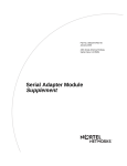
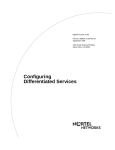
The TDM and ATM Connection
You can configure TDM for local connections only, unless you also configure
ATM. ATM provides the WAN connection that enables you to connect two remote
locations (for example, to connect video conferencing equipment) using CES. See
Figure 1-1.
CES
CES H.110 circuit
CBR PVC
TDM
ATM
TDM0002A
Figure 1-1.
Relationship Between ATM, TDM, and CES.
Where to Go Next
Use the following table to determine where to go next.
If you want to
Go to
Change default settings for TDM parameters
Chapter 2
Learn how to establish a point-to-point video
conference using TDM
Chapter 3
Obtain information about Site Manager parameters
Appendix A
Monitor TDM using the BCC show commands
Appendix B
309426-14.10 Rev 01
1-3
Chapter 2
Customizing TDM
When you start your router, TDM is already active and all TDM parameters use
their default values. However, you cannot transfer TDM data until you connect
both ends of the circuit. Once the circuit connection is complete, depending on the
requirements of your network, you may want to change some of the default
values. This chapter, which describes how to connect both ends of the TDM
circuit and customize TDM details, includes the following information:
Topic
Page
Starting Configuration Tools
2-2
Default TDM Configuration Parameters
2-2
Making a Switched H.110 TDM Circuit Connection
2-3
Making a CES H.110 TDM Circuit Connection
2-6
Disabling or Reenabling Data over a TDM Circuit
2-13
Setting the Clock Standard
2-14
Choosing the Clock Source
2-15
Partitioning the Timeslots
2-16
Determining the Number of Timeslots
2-18
Setting the Data Rate in the Timeslots
2-19
Where to Go Next
2-21
309426-14.10 Rev 01
2-1
Configuring TDM Services
Starting Configuration Tools
Before you can view or change the default TDM configuration, refer to the
following user guides for instructions on how to start and use the Nortel Networks
configuration tool of your choice.
Configuration Tool
User Guide
Bay Command Console (BCC)
Using the Bay Command Console (BCC)
Site Manager
Configuring and Managing Routers with
Site Manager
Default TDM Configuration Parameters
The following table lists the default TDM global configuration parameters:
Table 2-1.
Default TDM Global Configuration Parameters
Parameter
Default Value
Clock standard
T1
Clock source
Default clock
Timeslot partition
32 channels
The following table lists the default TDM circuit parameters.
Table 2-2.
2-2
Default TDM Circuit Parameters
Parameters
Default Value
Ability to send data over a TDM circuit
Enabled
Circuit type
Switched H.110
Data rate within each timeslot
64 Kb/s (full
timeslot)
Number of timeslots
1
309426-14.10 Rev 01
Customizing TDM
Making a Switched H.110 TDM Circuit Connection
By default, the router uses a switched H.110 circuit, which can connect two local
dual synchronous connectors. Use this type of circuit to connect video
conferencing equipment that connects to the same router.
Note: Once you connect the PORT connector to the other end of the circuit,
you cannot modify the circuit type. To modify the circuit type, you must first
unconnect the port.
Using the BCC
To connect both ends of a switched H.110 TDM circuit, you must create entries
for two dual synchronous connectors and then connect them.
1.
Create an entry for the first dual synchronous connector.
To create an entry for the first dual synchronous board, at the box prompt (for
example, box#) enter:
dsync slot <slot_number> pci-slot <pci_number> module <mod_number>
connector <connector_number>
slot_number is the slot number containing the dual synchronous module. The
slot number for the dual synchronous module is always 1.
pci_number is the number of the pci-slot containing the dual synchronous
board.
module_number is a convention used within the Passport 5430 chassis.
connector_number is the connector associated with this interface.
For example, to create an entry for the first dual synchronous connector
located at slot 1, pci-slot 4, module 2, connector 2, enter:
box# dsync/1/4/2/2# dsync slot 1 pci-slot 4 module 2 connector 2
dsync/1/4/2/2#
2.
Create an entry for the second dual synchronous connector.
To create an entry for the second dual synchronous connector, navigate to the
second dual synchronous board prompt (for example, box#; dsync 1/4/2/2)
and enter:
dsync slot <slot_number> pci-slot <pci_number> module <mod_number>
connector <connector_number>
309426-14.10 Rev 01
2-3
Configuring TDM Services
slot_number is the slot number containing the dual synchronous module. The
slot number for the dual synchronous module is always 1.
pci_number is the number of the pci-slot containing the dual synchronous
board.
module_number is a convention used within the Passport 5430 chassis.
connector_number is the connector associated with this interface.
For example, to create an entry for the second dual synchronous connector
located at slot 1, pci-slot 4, module 1, connector 1, enter:
box# dsync/1/4/2/2# dsync slot 1 pci-slot 4 module 1 connector 1
3.
Connect the first dual synchronous connector to the second dual
synchronous connector.
To connect the two dual synchronous connectors, navigate to the second dual
synchronous connector prompt (for example, box#; dsync 1/3/1/1), and
enter:
connect sslot <slot_number> spci-slot <pci_number> smodule
<mod_number> sconnector <connector_number>
slot_number is the slot number containing the dual synchronous module. The
slot number for the dual synchronous module is always 1.
pci_number is the number of the pci-slot containing the dual synchronous
board.
module_number is a convention used within the Passport 5430 chassis.
connector_number is the connector associated with this interface.
For example, to connect the first dual synchronous connector located at slot 1,
pci-slot 4, module 2, connector 2 to the second dual synchronous connector
located at slot 1, pci-slot 4, module 1, connector 1, enter:
box# dsync/1/4/2/2# connect sslot 1 spci-slot 4 smodule 1 sconnector
1
2-4
309426-14.10 Rev 01
Customizing TDM
Using Site Manager
To connect both ends of a switched H.110 TDM circuit, complete the following
tasks:
Site Manager Procedure
You do this
System responds
1. In the Configuration Manager window,
click on the PORT connector.
The Edit Connector window opens.
2. Click on Edit TDM.
The Edit Circuit TDM Parameters window
opens.
3. Set the TDM Resource parameter to
Switched_H.110 for switched H.110 TDM
circuit enabling local connections only.
4. Click on OK.
You return to the Edit Connector window.
5. Click on Config TDM if you chose a
switched H.110 circuit to connect two local
dual synchronous connectors.
6. Click on Connect.
The Switched or CES H.110 Connector
window opens.
7. Click on Connect.
The Switched or CES H.110 Circuit List
window opens.
8. Click on Done.
You return to the Configuration Manager
window.
309426-14.10 Rev 01
2-5
Configuring TDM Services
Making a CES H.110 TDM Circuit Connection
You can set the circuit type to CES H.110 if you want to connect a dual
synchronous port with an ATM PVC on an ATM T1/E1 port so that you can
emulate TDM functionality over ATM using CES. This type of circuit enables you
to connect video conferencing equipment in two different remote locations.
Note: Once you connect the PORT connector to the other end of the circuit,
you cannot modify the circuit type. To modify the circuit type, you must first
disconnect the port.
To connect both ends of a CES H.110 TDM circuit, complete the following steps:
•
Create an entry for the dual synchronous connector.
•
Create an entry for the ATM connector.
•
Define an ATM PVC service record that uses null encapsulation.
•
Create an ATM PVC that uses AAL 1 encapsulation and uses the CBR service
category.
•
Start CES to connect the dual synchronous connector to the ATM PVC.
Using the BCC
1.
Create an entry for the dual synchronous connector.
To make a CES H.110 TDM circuit connection, first navigate to the box
prompt (for example, box#) and enter:
dsync slot <slot_number> pci-slot <pci_number> module <mod_number>
connector <connector_number>
slot_number is the slot number containing the dual synchronous module. The
slot number for the dual synchronous module is always 1.
pci_number is the number of the pci-slot containing the dual synchronous
board.
module_number is a convention used within the Passport 5430 chassis.
connector_number is the connector associated with this interface.
2-6
309426-14.10 Rev 01
Customizing TDM
For example, to create an entry for the first dual synchronous connector
located at slot 1, pci-slot 4, module 2, connector 2, enter:
box# dsync slot 1 pci-slot 4 module 2 connector 2
dsync/1/4/2/2#
2.
Create an entry for an ATM T1/E1 connector.
Next, navigate to the box prompt (for example, box#) to add ATM to the
configuration so that you can connect an ATM PVC to the dual synchronous
connector, and enter:
atm slot <slot_number> pci-slot <pci_slot_number> module
<module_number> connector <connector_number> mode <mode>
To add ATM to the configuration, navigate to the top-level prompt and enter:
atm slot <slot_number> pci-slot <pci_slot_number> module
<module_number> connector <connector_number>
slot_number is the number of the chassis slot containing the link module.
pci_slot_number is the pci-slot number of the ATM-E1/ATM-T1 line. The pci
slot number for the ATM router is always 1.
module_number is a convention used within the Passport 5430 or System
5000 chassis. You need only enter a module number when configuring an
ATM router in the Passport 5430 or System 5000 chassis (that is, the Model
5782 Centillion Multiprotocol Engine). The module number for the ATM
router is always 1.
connector_number is the number of a connector on the link module
mode is the frequency mode you want to use, either T1 or E1.
For example, to create an ATM entry at slot 1, pci-slot 1, module 2,
connector 1, using the T1 mode, enter:
box# atm slot 1 pci-slot 1 module 2 connector 1 mode t1
atm/1/1/2/1#
3.
Define an ATM PVC service record.
To define an ATM PVC service record, navigate to the ATM interface prompt
(for example, box#;atm/1/1/2/1) and enter:
pvc-service <service_name> encapsulation <encapsulation_type>
service_name is a unique text string that you assign to the service record.
309426-14.10 Rev 01
2-7
Configuring TDM Services
encapsulation_type is the data encapsulation type that you want the PVC
service record to use.
When configuring a CES H.110 TDM circuit, you must define an ATM
service record that uses null encapsulation.
For example, the following command defines a PVC service record with the
name “ces1422” and that uses null encapsulation on ATM slot 1, pci-slot 1,
module 2, connector 1:
atm/5/1# pvc-service service-name ces1422 encapsulation null
pvc-service/ces1422#
4.
Add an ATM PVC to the PVC service record.
To add a PVC to a PVC service record, navigate to the ATM PVC service
record prompt (for example, box#;atm/1/1/2/1;pvc-service/ces1422), and
enter:
pvc vpi <vpi_number> vci <vci_number>
vpi_number identifies the virtual path of the PVC. The header can contain a
maximum of 8 VPI bits for a UNI connection. This bit range allows for path
identifiers from 0 to 255.
vci_number identifies the virtual channel of the PVC. The header can contain
a maximum of 16 VCI bits. This bit range allows for channel identifiers from
32 to 65535.
Note: Following the recommendation of the ATM Forum, virtual channel
identifiers from 0 to 31 are reserved for signaling and added functionality.
For example, the following command adds PVC 32/33 to the configuration on
PVC service record ces1422:
pvc-service/ces1422# pvc vpi 32 vci 33
pvc/32/33#
5.
Set the AAL encapsulation type of the ATM PVC to AAL 1.
To set the AAL encapsulation type to AAL 1, navigate to the ATM PVC
prompt (for example, box#;atm/1/1/2/1;pvc-service/ces1422;pvc/32/33),
and enter:
aal-type aal1
6.
2-8
Set the service category of the ATM PVC to constant bit rate (CBR).
309426-14.10 Rev 01
Customizing TDM
To set the service category to CBR, navigate to the ATM PVC prompt (for
example, box#;atm/1/1/2/1;pvc-service/ces1422;pvc/32/33), and enter:
service-category cbr
7.
Connect a dual synchronous connector to an ATM PVC.
To connect the dual synchronous connector to the ATM PVC, navigate to the
ATM PVC prompt (for example, box#;atm/1/1/2/1;pvc-service/
ces1422;pvc/0/130) and enter:
ces sslot <slot_number> spci-slot <pci_number> smodule <mod_number>
sconnector <conn_number>
connect sslot <slot_number> spci-slot <pci_number> smodule
<mod_number> sconnector <connector_number>
slot_number is the slot number containing the dual synchronous module. The
slot number for the dual synchronous module is always 1.
pci_number is the number of the pci-slot containing the dual synchronous
board.
smodule_number is a convention used within the Passport 5430 chassis.
connector_number is the connector associated with this interface.
For example, to connect an ATM PVC, located at slot 1, pci-slot 1, module 2,
connector 1 with a VCI/VPI pair of 32/33, to the dual synchronous connector
located at slot 1, pci-slot 4, module 2, connector 2, enter the following
command:
pvc/1/1/2/1/32/33# ces 1/4/2/2
Using Site Manager
To make a CES H.110 TDM circuit connection, complete the following tasks:
1.
Configure a dual synchronous board.
Site Manager Procedure
You do this
System responds
1. In the Site Manager window, click on
Configuration Manager.
The Open Configuration File window
opens.
2. Specify a configuration file name and click The Select Router Model window opens.
on Save.
309426-14.10 Rev 01
2-9
Configuring TDM Services
Site Manager Procedure (continued)
You do this
System responds
3. Click on Passport 5430 and then click on
Confirm.
The Configuration manager window
opens.
4. Click on Empty Module.
The Module List window opens.
5. Select Dual Sync and click on OK.
You return to the Configuration Manager
window. Two PORT connectors on the
dual synchronous board are now
available.
6. Click on one of the PORT connectors.
The Add Circuit window opens.
7. Click on OK.
You return to the Configuration Manager
window.
2.
Establish a TDM CES H.110 circuit.
Site Manager Procedure
You do this
System responds
1. In the Configuration Manager window,
click on the PORT connector.
The Edit Connector window opens.
2. Click on Edit TDM.
The Edit Circuit TDM Parameters window
opens.
3. Set the TDM Resource parameter to
CES_H110.
2-10
4. Click on OK.
You return to the Edit Connector window.
5. Click on Done.
You return to the Configuration Manager
window.
309426-14.10 Rev 01
Customizing TDM
3.
Establish an ATM PVC having AAL 1 encapsulation and CBR service
category.
When you establish an ATM PVC, be sure to set the AAL Type to 1 and the
service category to CBR.
Site Manager Procedure
You do this
System responds
1. In the Configuration Manager window,
click on Empty ATM T1/E1 Module.
The Module List window opens.
2. Select ATM T1/E1 and click on OK.
You return to the Configuration Manager
window. An ATM connector is now
available.
3. Click on the ATM connector.
The Add Circuit window opens.
4. Click on OK.
The ATM Configuration window opens.
5. Click on ATM.
The Edit ATM Connector window opens.
6. Click on Service Attributes.
The ATM Service Records List window
opens.
7. Click on PVC.
The ATM Service Records parameters
window opens.
8. Accept the default values and click on OK. The Select Protocols window opens.
9. Add one or more protocols (such as IP)
and configure those protocols.
The ATM Virtual Channel Link window
opens.
10. Click on Add.
The ATM Virtual Channel Link
Parameters window opens.
11. Enter the VPI/VCI Pair. For information on
how to configure these parameters, see
Configuring ATM Services.
12. Click on OK.
You return to the ATM Virtual Channel
Link window.
13. Highlight the virtual channel and configure
the following parameters:
• AAL Type parameter to AAL 1
encapsulation.
• Service Category to CBR.
14. Click on Apply.
(continued)
309426-14.10 Rev 01
2-11
Configuring TDM Services
Site Manager Procedure (continued)
You do this
System responds
15. Click on Done.
You return to the ATM Service Records
List window.
16. Click on Done.
You return to the Edit ATM Connector
window.
17. Click on Done.
You return to the ATM Configuration
window.
18. Click on Done.
You return to the Configuration Manager
window.
4.
Configure CES.
Site Manager Procedure
2-12
You do this
System responds
1. In the Configuration Manager window,
click on the PORT connector.
The Edit Connector window opens.
2. Click on Config CES.
The CES H.110 Circuit window opens.
3. Click on Connect.
The CES H.110 Circuit List window
opens.
4. Highlight the CES H.110 circuit and click
on OK.
You return to the Edit Connector window.
5. Click on Done.
You return to the Configuration Manager
window.
309426-14.10 Rev 01
Customizing TDM
Disabling or Reenabling Data over a TDM Circuit
By default, when you create a TDM circuit, data traffic over that circuit is
enabled. You can disable and reenable the traffic over a TDM circuit. Changing
the state of the traffic over a TDM circuit is useful, for example, when you want to
hang up (disable) a conference call.
Using the BCC
To disable traffic over a TDM circuit, navigate to the dual synchronous connector
prompt (for example, box#; dsync 3/1/1) and enter:
state disabled
To enable traffic over a TDM circuit, navigate to the dual synchronous connector
prompt (for example, box#; dsync 3/1/1) and enter:
state enabled
Using Site Manager
To disable or reenable traffic over a TDM circuit, complete the following tasks:
Site Manager Procedure
You do this
System responds
1. In the Configuration Manager window,
click on the PORT connector.
The Edit Connector window opens.
2. Click on Edit Line.
The Edit DSYNC PMC Parameters
window opens.
3. Set the Enable parameter. Click on Help
or see the parameter description on
page A-3.
4. Click on OK.
You return to the Edit Connector window.
5. Click on Done.
You return to the Configuration Manager
window.
309426-14.10 Rev 01
2-13
Configuring TDM Services
Setting the Clock Standard
Before configuring a TDM circuit, you can set the TDM clock standard to use the
default clock or to use either the T1 or E1 frequency. By default, the TDM clock
standard is set to the standard that will be used for TDM. The TDM clock standard
affects all TDM circuits (CES and switched.)
Note: A change to the TDM clock standard takes effect only after you reboot
the router with the new configuration file. Any change to the timeslot partition
also requires that you save your configuration and reboot. To save time, you
may want to be sure you have configured both the TDM clock standard and the
timeslot partition before you save your configuration and reboot.
Using the BCC
To set the clock standard, navigate to the TDM prompt (for example, box#; tdm)
and enter:
clock-standard <frequency>
frequency specifies whether you are using the T1 or E1 clock frequency for the
clock standard.
For example, the following command chooses the E1 frequency as the clock
standard:
tdm# clock-standard e1
2-14
309426-14.10 Rev 01
Customizing TDM
Using Site Manager
To set the TDM clock standard, complete the following tasks:
Site Manager Procedure
You do this
System responds
1. In the Configuration Manager window,
click Platform >TDM > Clock
Connectors.
The TDM Clock Parameters window
opens.
2. Highlight the clock that you want to set
and choose from the oscillator or ATM
clock options. Otherwise, click on Select
All to change all clock settings or
Deselect All to revert all clocks to the
default setting.
3. Click on OK.
You return to the Configuration Manager
window.
Choosing the Clock Source
TDM initially uses the default clock. You can use either the default clock or the
clock from a configured connector (such as the ATM T1/E1, or T1/E1.)
Using the BCC
To set the clock source, navigate to the TDM prompt (for example, box#;atm/1/1/
2/1; tdm) and enter:
clockx <source>
x is the number that identifies clocks 1 through 8.
source is the clock source you want to use.
For example, to set the first clock source to ATM, where the ATM connector is
1201, enter:
box# atm 1/1/2/1 mode t1
atm/1/1/2/1# tdm
tdm# clock1 1201
309426-14.10 Rev 01
2-15
Configuring TDM Services
Using Site Manager
To choose a clock source, enter the following commands:
Site Manager Procedure
You do this
System responds
1. In the Configuration Manager window,
click Platform >TDM > Clock
Connectors.
The TDM Clock Parameters window
opens.
2. Highlight the clock number and select the
clock source from the pull down menu.
3. Click on OK.
You return to the Configuration Manager
window.
Partitioning the Timeslots
Partitioning the timeslots determines the maximum number of 64 Kb/s and
56 Kb/s timeslots for all circuits. When you partition the timeslots, you must
specify an even number of channels to reserve for the 64 Kb/s virtual trunk. The
remainder of the channels will be reserved for the 56 Kb/s trunk.
If you add more CES TDM circuits and run out of 64 Kb/s timeslot space, then
you need to change the partition to allocate more 64 Kb/s timeslot spaces (which
leaves you fewer 56 Kb/s timeslot spaces). Use the BCC show tdm partition
command to determine how many 56 Kb/s channels are available.
2-16
309426-14.10 Rev 01
Customizing TDM
Using the BCC
Note: A change to the timeslot partition takes effect only after you reboot the
router with the new configuration file. Any change to the TDM clock standard
also requires that you save your configuration and reboot. To save time, you
may want to be sure you’ve configured both the TDM clock standard and the
timeslot partition before you save your configuration and reboot.
To partition the timeslots, navigate to the TDM prompt (for example, box#; tdm)
and enter:
tdm# timeslot-partition <integer>
integer is the number of channels per virtual trunk.
For example, the following command allocates 30 64 Kb/s timeslots with the
remainder reserved for 56 Kb/s timeslots:
tdm# timeslot-partition 30
Using Site Manager
To partition the timeslots, complete the following tasks:
Site Manager Procedure
You do this
System responds
1. In the Configuration Manager window,
click Platform >TDM > Global.
The Edit TDM Global Parameters window
opens.
2. Set the Timeslot Partition parameter.
Click on Help or see the parameter
description on page A-2.
3. Click on OK.
309426-14.10 Rev 01
You return to the Configuration Manager
window.
2-17
Configuring TDM Services
Determining the Number of Timeslots
The number of timeslots that are available depends on your setting for the data
rate. If you choose to send 64 Kb/s data, you can have more than 1 timeslot
available to transmit data. If you choose to send 56 Kb/s data, then you can have
only 1 timeslot available for data transmission.
Using the BCC
To allocate the number of timeslots for a switched H.110 circuit, navigate to the
connect prompt (for example, box#; dsync 1/4/2/2; dsync 1/4/2/2; connect 1/4/
2/2) and enter:
For example, the following command allocates the number of timeslots assigned
to the switched H.110 circuit.
timeslots <integer>
integer is the number of timeslots that you want to use.
For example, the following command allocates three timeslots.
connect/2/1/1/1/2/1# timeslots 3
To allocate the number of timeslots for a CES H.110 circuit, navigate to the CES
prompt (for example, box#; dsync 1/4/2/2;atm 1/1/2/1 mode t1;pvc-service
ces1422;pvc 1/1/2/1/32/33;ces 1/4/2/2) and enter:
timeslots <integer>
integer is the number of timeslots that you want to use.
For example, the following command allocates three timeslots.
connect/2/1/1/1/2/1# timeslots 3
2-18
309426-14.10 Rev 01
Customizing TDM
Using Site Manager
To allocate the number of timeslots, complete the following tasks:
Site Manager Procedure
You do this
System responds
1. In the Configuration Manager window,
click Platform >TDM > Connections.
The TDM Connections window opens.
2. Set the Number of Timeslots parameter.
Click on Help or see the parameter
description on page A-3.
3. Click on OK.
You return to the Configuration Manager
window.
Setting the Data Rate in the Timeslots
You can determine the rate at which data can travel within each and every timeslot
in the circuit, as follows:
•
Select 64K for a full timeslot. When you select 64K, the data rate is 64 Kb/s
times the number of timeslots for the 64 Kb/s timeslots.
•
Select 56K MSB to set the most significant bit (that is, the first bit on the
wire) to 1 and have data carried on the next 7 bits. If you select 56K, you can
have only one timeslot and the data rate is 56 Kb/s.
•
Select 56K LSB to carry data on the first 7 bits. Set the least significant bit
(that is, the last bit) to 1. If you select 56K, you can have only one timeslot
and the data rate is 56 Kb/s.
309426-14.10 Rev 01
2-19
Configuring TDM Services
Using the BCC
To set the data rate for a switched H.110 circuit, navigate to the connect prompt
(for example, box#; dsync 1/4/2/2; dsync 1/4/2/2; connect 1/4/2/2) and enter:
timeslot-subrate <value>
value is the rate at which data travels in the timeslots.
For example, the following command allocates a full 64 Kb/s for data within each
timeslot on the switched H.110 circuit.
connect/2/1/1/1/2/1# timeslot-subrate 64k
To set the data rate for a CES H.110 circuit, navigate to the CES prompt (for
example, box#; dsync 1/4/2/2;atm 1/1/2/1 mode t1;pvc-service ces1422;pvc 1/
1/2/1/32/33;ces 1/4/2/2) and enter:
timeslot-subrate <value>
integer is the rate at which data travels in the timeslots.
For example, the following command allocates a full 64 Kb/s for data within each
timeslot on the CES H.110 circuit.
ces/32/33/1/4/2/2# timeslot-subrate 64k
Using Site Manager
To determine the data rate for each timeslot in the partition, complete the
following tasks:
Site Manager Procedure
You do this
System responds
1. In the Configuration Manager window,
click Platform >TDM > Connections.
The TDM Connections window opens.
2. Set the Per-Timeslot Subrate parameter.
Click on Help or see the parameter
description on page A-3.
3. Click on OK.
2-20
You return to the Configuration Manager
window.
309426-14.10 Rev 01
Customizing TDM
Where to Go Next
Use the following table to determine where to go next.
If you want to
Go to
Learn about TDM.
Chapter 1
Learn how to establish a point-to-point video
conferencing session using TDM.
Chapter 3
Obtain information about Site Manager parameters.
Appendix A
Monitor TDM using the BCC show commands.
Appendix B
309426-14.10 Rev 01
2-21
Chapter 3
Video Conferencing
This chapter, which describes how to set up a point-to-point video conference,
includes the following information:
Topic
Page
Hardware Requirements
3-1
Setting Up a Video Conference
3-3
Where to Go Next
3-3
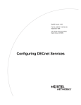
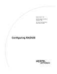
Hardware Requirements
A point-to-point video conference requires that you have video conferencing
equipment at two or more remote locations. As shown in Figure 3-1, this
equipment consists of:
•
A Passport 5430 with a dual synchronous module
•
Cameras, televisions, etc., supplied by a vendor such as PictureTel, Vtel, or
Vcon
•
A V.35 interface
•
A line speed capable of 56, 64, 128, 192, 256, 320, and 384 Kb/s
309426-14.10 Rev 01
3-1
Configuring TDM Services
LOOP
YEL
ALM
RED
ALM
ATM
T1/E1
SYNC
TDM
circuit
SYNC
LOOP
YEL
ALM
RED
ALM
ATM
Module
Daul
T1/E1
ATM
Module
Daul
T1/E1
TDM
circuit
ATM
T1/E1
ATM
Dual
Synchronous
E1/T1 connection
Dual
Synchronous
E1/T1 connection
Passport 5430
Video conference
at remote office 1
Passport 5430
Video conference
at remote office 2
TDM0001A
Figure 3-1.
3-2
Sample Video Conferencing Session Using TDM
309426-14.10 Rev 01
Video Conferencing
Setting Up a Video Conference
To set up a video conference, first disable dialing and ensure that all equipment
supports a direct connection. Next, follow the instructions for how to make a CES
H.110 TDM connection in “Making a CES H.110 TDM Circuit Connection” on
page 2-6.
Where to Go Next
Use the following table to determine where to go next.
If you want to
Go to
Learn about TDM.
Chapter 1
Change default settings for TDM parameters.
Chapter 2
Obtain information about Site Manager parameters.
Appendix A
Monitor TDM using the BCC show commands.
Appendix B
309426-14.10 Rev 01
3-3
Appendix A
Site Manager Parameters
After you enable a TDM circuit, you can use Site Manager parameters to edit
TDM parameters. Many TDM parameters are interdependent; how you edit some
parameters depends on how you set others.
This appendix contains the Site Manager parameter descriptions for TDM
services. You can display the same information using Site Manager online Help.
This appendix contains the following information:
Topic
Page
Circuit TDM Resource Parameter
A-2
TDM Global Parameters
A-2
Dual Synchronous PMC Parameters
A-3
309426-14.10 Rev 01
A-1
Configuring TDM Services
Circuit TDM Resource Parameter
The circuit TDM resource parameter determines whether the TDM circuit can
make a local or remote connection.
Parameter: TDM Resource
Path:
Default:
Options:
Function:
Instructions:
Configuration Manager > Connector > Edit TDM
Switched_H110
Switched_H110 | CES_H110
Identifies the TDM circuit used by this resource.
Select CES_H110 to emulate TDM functionality over an ATM circuit. Select
Switched_H110 to establish a local connection between two dual synchronous
ports. Use switched H.110 circuits mainly for testing purposes.
MIB Object ID: 1.3.6.1.4.1.18.3.3.2.3.1.10
TDM Global Parameters
The TDM global parameters determine the box-wide behavior of the TDM circuit.
Parameter: Clock Standard
Path:
Default:
Options:
Function:
Instructions:
MIB Object ID:
Configuration Manager > Platform > TDM > Global
T1
T1 | E1
Specifies the frequency (T1 or E1) of the H.110 clock sources.
Select T1 or E1.
1.3.6.1.4.1.18.3.3.2.9.3.3.1.3
Parameter: Timeslot Partition
Path:
Default:
Options:
Function:
Configuration Manager > Platform > TDM > Global
32
0 through 64
Specifies the number of channels to reserve for the 64 Kb/s virtual trunk. The
remainder of the channels will be reserved for the 56 Kb/s trunk. Your setting
for timeslot partition must be an even number.
Instructions: Select an even number between 0 and 64.
MIB Object ID: 1.3.6.1.4.1.18.3.3.2.9.3.4.1.3
A-2
309426-14.10 Rev 01
Site Manager Parameters
Dual Synchronous PMC Parameters
The dual synchronous PMC parameters determine the behavior of the TDM
circuit on an individual timeslot basis.
Parameter: Enable
Path:
Default:
Options:
Function:
Instructions:
Configuration Manager > Connector > Edit Line
Enable
Enable | Disable
Enables traffic over a TDM circuit.
Select Enable to enable traffic over a TDM circuit. Select Disable to disable
traffic over a TDM circuit.
MIB Object ID: 1.3.6.1.4.1.18.3.3.2.9.3.5.1.2
Parameter: Per-Timeslot Subrate
Path:
Default:
Options:
Function:
Instructions:
Configuration Manager > Connector > Edit Line
Subrate_64K
Subrate_64K | Subrate_56KMSB | Subrate_64KLSB
Specifies data rate for each timeslot within a TDM circuit.
Accept the default, 64K, for a full timeslot. Select 56KMSB to send 56 Kb/s
data and set the first bit on the wire and have data carried on the next 7 bits.
Select 56KLSB to send 56 Kb/s data and carry data on the first 7 bits and set the
last bit to 1.
MIB Object ID: 1.3.6.1.4.1.18.3.3.2.9.3.5.1.7
Parameter: Number of Timeslots
Path:
Default:
Options:
Function:
Configuration Manager > Connector > Edit Line
1
1 through 32
Number of TDM circuit timeslots occupied by this interface. Since TDM
circuits are full-duplex, setting this attribute to N will allocate N transmit
timeslots and N receive timeslots.
Instructions: Accept the default or select a value from 1 to 32.
MIB Object ID: 1.3.6.1.4.1.18.3.3.2.9.3.5.1.8
309426-14.10 Rev 01
A-3
Appendix B
BCC Show Commands
This appendix describes how to use the BCC show commands to obtain TDM and
DSYNC statistical data from the management information base (MIB). The type
and amount of data displayed depend on the specific TDM and DSYNC settings
that you want to view. This appendix includes descriptions of the following show
commands:
Command
Page
show dsync config
B-2
show dsync stats
B-3
show switched-h110 config
B-3
show switched-h110 stats
B-4
show tdm h110 clock
B-5
show tdm partition
B-5
309426-14.10 Rev 01
B-1
Configuring TDM Services
show dsync config
The show dsync config command displays all dual synchronous port information.
This command allows for the following command filter (flag) and filter arguments:
-circuit <circuit_name>
Displays information about the specified dual synchronous circuit.
The output includes the following information:
B-2
Slot/Pci_Slot/Module/
Connector
The slot/Pci_Slot/module/connector location of the DualSync
interface.
Circuit Name
Circuit name assigned to the interface.
Oper. Stats
The current state of this interface.
Timeslot Subrate
The data rate within each and every timeslot within this TDM circuit.
Timeslot Number
Number of timeslots occupied by this H.110 TDM circuit.
Total Up Time
The total time the interface has been in its current operational state
(UP state) since boot.
TDM Resource
The type of the TDM resource.
TDM Connection
The indication of whether this TDM circuit is currently in use.
309426-14.10 Rev 01
BCC Show Commands
show dsync stats
The show dsync stats command displays all status of all dual synchronous ports.
This command allows for the following command filter (flag) and filter arguments:
-circuit <circuit_name>
Displays information about the specified dual synchronous circuit.
The output includes the following information:
Slot/Pci_Slot/Module/
Connector
The slot/Pci_Slot/module/connector location of the DualSync
interface.
Circuit Name
Circuit name assigned to the interface.
Oper. Stats
The current state of this interface.
Receive Bytes
Number of octets received.
Transmit Bytes
Number of octets transmitted.
Cable Type
The type of the cable attached to the TDM interface port.
EIA Status
The state of the EIA signals at the router interface.
show switched-h110 config
The show switched-h110 config command displays all TDM dual synchronous switched
connection information.
The output includes the following information:
DualSync Slot/Pci_Slot/
Module/Connector
The first DualSync Slot/Pci_Slot/Module/Connector location of the
TDM switched connection.
DualSync Slot/Pci_Slot/
Module/Connector
The second DualSync Slot/Pci_Slot/Module/Connector location of
the TDM switched connection.
Circuit Name
Circuit name assigned to the interface.
Timeslot Subrate
The data rate within each and every timeslot within this TDM circuit.
Timeslot Partition
Number of timeslots occupied by this H.110 TDM circuit.
Oper. State
State of the TDM switched connection.
309426-14.10 Rev 01
B-3
Configuring TDM Services
show switched-h110 stats
The show switched-h110 stats command displays all TDM dual synchronous switched
connection status information.
The output includes the following information:
B-4
Conn
Connector number of the interface.
Slot/Pci_Slot/Module/
Connector
The DualSync Slot/Pci_Slot/Module/Connector location of the TDM
switched connection.
Circuit Name
Circuit name assigned to the interface.
Timeslot Subrate
The data rate within each and every timeslot within this TDM circuit.
Timeslot Partition
The number of timeslots occupied by this H.110 TDM circuit.
Oper. State
State of the TDM line: Up, Down, Init (initializing), Disabled, or
Absent.
Receive Bytes
Number of octets received.
Transmit Bytes
Number of octets transmitted.
309426-14.10 Rev 01
BCC Show Commands
show tdm h110 clock
The show tdm h110 clock command displays all H.110 clock source connector
information for the TDM manager on the Passport 5430.
The output includes the following information:
Clock Standard
The frequency (T1 or E1) of the H.110 clock sources.
Current Clock State
The state of the current clock source.
Current Clock Source
The currently active H.110 clock source
Clk 1
The GAME Instance Id Connector of H.110 clock source 1.
Clk 2
The GAME Instance Id Connector of H.110 clock source 2.
Clk 3
The GAME Instance Id Connector of H.110 clock source 3.
Clk 4
The GAME Instance Id Connector of H.110 clock source 4.
Clk 5
The GAME Instance Id Connector of H.110 clock source 5.
Clk 6
The GAME Instance Id Connector of H.110 clock source 6.
Clk 7
The GAME Instance Id Connector of H.110 clock source 7.
Clk 8
The GAME Instance Id Connector of H.110 clock source 8.
Clk 9
The GAME Instance Id Connector of H.110 clock source 9.
show tdm partition
The show tdm partition command displays the timeslot partition information for the
TDM manager on the Passport 5430.
The output includes the following information:
Timeslot Partition 64K Channel
Number of channels to reserve for the 64 Kb/s virtual trunk.
Timeslot Partition 56K Channel
Number of channels reserved for the 56 Kb/s virtual trunk.
309426-14.10 Rev 01
B-5
Index
A
acronyms, xiii
ATM
configuration tools, 2-2
interface, customizing, 2-1
E
emulating TDM functionality over ATM, 1-2
Enable parameter, A-3
enabling TDM traffic, 2-13
B
N
BCC show commands, B-1
number of timeslots, 2-18
C
Number of Timeslots parameter, A-3
CBR, 1-2
P
CES, 1-2, 2-6
clock source, 2-15
parameters
Clock Standard, A-2
Enable, A-3
Number of Timeslots, A-3
Per-Timeslot Subrate, A-3
TDM Resource, A-2
Timeslot Partition, A-2
clock standard, 2-14
partitioning timeslots, 2-16
Clock Standard Parameter, A-2
Passport 5430, 1-1
constant bit rate (CBR), 1-2
permanent virtual circuit, 1-2
conventions, text, xii
Per-Timeslot Subrate parameter, A-3
customer support, xiv
PMC modules, 1-1
CES H.110 circuit, 1-1, 2-6
circuit
CES H.110, 1-1
switched H.110, 1-1
Circuit Emulation Services (CES), 1-2
product support, xiv
D
protocols, 1-1
data rate, 2-19
publications
hard copy, xiv
default configuration, 2-2
disabling TDM traffic, 2-13
PVC, 1-2
PVCs, defining service records for, 2-7
dual synchronous connectors, 1-2, 2-3
309426-14.10 Rev 01
Index-1
S
show commands, B-1
Site Manager parameters, A-1
super-serial daughterboard, 1-1
support, Nortel Networks, xiv
switched H.110 circuit, 1-1, 2-3
T
TDM configuration, default, 2-2
TDM Resource parameter, A-2
TDM traffic
disabling, 2-13
enabling, 2-13
TDM, defined, 1-1
technical publications, xiv
technical support, xiv
text conventions, xii
Time division multiplexing, defined, 1-1
time-bandwidth multiplexing, 1-1
Timeslot Partition parameter, A-2
timeslot subrate, 2-20
timeslots, 1-1
partitions, 2-16
V
video conferencing
local, 2-3
remote locations, 2-6
voice and video systems, 1-1
Index-2
309426-14.10 Rev 01