1
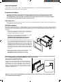
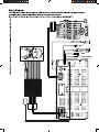
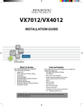
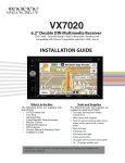
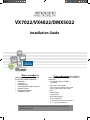
VX7022/VX4022/DMX5022
Installation Guide
What’s in the Box The
following items are supplied with
the VX7022/VX4022/DMX5022:
•
•
•
•
•
•
•
HeadUnit
Trim Ring
Hardware Bag
Power/Speaker Output Harness
Remote Control
External Microphone
Installation Guide
Tools and Supplies The following
tools and supplie are needed to install the
head unit:
• Torx type, flat-head and Philips
screwdrivers
• Wire cutters and strippers
• Tools to remove existing radio (screw
driver, socket wrench set or other
tools)
• Electrical tape
• Crimping tool
• Volt meter/test light
• Crimp connections
• 18 gauge wire for power connections
• 16 – 18 gauge speaker wire
WARNING! Never install this unit where operation and viewing could interfere with
safe driving conditions.
Optional Equipment
Steering Wheel Control Interface (SWC) - The VX7022/VX4022/DMX5022 are compatible with various PAC, Metra and
Step 1-c
iDatalink Maestro SW steering wheel control adapters.
Disconnect the Battery
• To prevent a short circuit, be sure to turn off the ignition and remove the negative (-) battery cable prior to installation.
NOTE: If the head unit is to be installed in a car equipped with an on-board drive or navigation computer,
TAB do not
disconnect the battery cable. If the cable is disconnected, the computer memory may be lost. Under these conditions,
use extra caution during installation to avoid causing a short circuit.
DASHBOARD
Replacing the Fuse
• When replacing the vehicles Radio fuse always use the proper rated replacement fuse. Using a fuse with an improper rating
could damage the unit and cause a fire.
Step 2
ISO-DIN Installation
The head unit is designed to fit into a 2.0 DIN dashboard opening. The unit has threaded holes in the chassis side panels which
may be used with the original factory mounting brackets of some Toyota, Nissan, Mitsubishi, Isuzu, Hyundai and Honda vehicles to
mount the radio to the dashboard. Please consult with your local car stereo specialty shop for assistance on this type of
installation.
1.Remove the existing factory radio from the dashboard or
center console mounting. Save all hardware and brackets as
they will be used to mount the new radio.
2. Remove the factory mounting brackets and hardware from the
existing radio and attach them to the new radio.
CAUTION! Do not exceed M5 X 6MM screw size. Longer
screws may damage components inside the chassis.
3. Place the radio in front of the dashboard opening so the wiring
can be brought through the mounting sleeve. Follow the
wiring diagram carefully and make certain all connections are
secure and insulated with wire nuts or electrical tape. After
completing the wiring connections, plug the connector into
the mating socket on the rear of the chassis. Turn the unit on
to confirm operation (vehicle ignition switch must be “ON”). If
the unit does not operate, re-check all wiring until the problem
is corrected.
Step 5-c
4. Mount the new radio assembly to the dashboard or center
console using the reverse procedure in step 1 above.
CAUTION! Be careful not to damage the car wiring.
NOTE: It is the end-users responsibility to install and operate this unit in a manner in accordance with local, state and federal
laws. The PARKING BRAKE wire MUST BE CONNECTED as directed in the manual.
Using the Cosmetic Trim Ring
A cosmetic trim ring is supplied with the head unit for installation
flexibility. This unit will fit into most import dashes with little or
no modification to the dash board/cavity. Some US domestic
vehicle dashes will accept a Double-DIN chassis, but there is
usually a small gap between the radio and dash piece after
installation is complete. In this case, use the trim ring to conceal
any gaps that may be present.
NOTE: For proper operation of the CD/DVD player, the chassis must be mounted within 30° of horizontal. Make sure the
unit is mounted within this limitation.
2
HDMI
-
Black
SiriusXM
Black
Black
WHITE
WHITE/BLACK
GRAY
GRAY/BLACK
PURPLE
PURPLE/BLACK
GREEN
GREEN/BLACK
YELLOW
BLACK
RED
ORANGE
BLUE
PINK
GREEN/WHITE
BROWN/BLACK
WHITE/PURPLE
WHITE/BROWN
LEFT FRONT SPEAKER (+)
PEAKER (-)
LEFT FRONT SPEAKER
(-)
SPEAKER (+)
RIGHT FRONT SPEAKER
SPEAKER (+)
(-)
RIGHT FRONT SPEAKER (-)
RIGHT REAR SPEAKER (+)
RIGHT REAR SPEAKER (-)
LEFT REAR SPEAKER (+)
LEFT REAR SPEAKER (-)
BATTERY 12V (+)
GROUND (-)
ACC / IGNITION (+)
POWER ANT & AMP (+)
BRAKE (-)
REVERSE (+)
SWC GND
SWC A
SWC B
GPS Antenna (VX7022 Only)
Voxx Electronics Corporation
Hauppauge, NY 11788
Technical Assistance: 800-323-4815
www.jensenmobile.com
© 2015
Printed in China
12707100XXXX