1
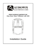
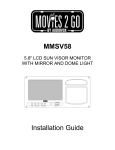
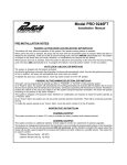
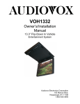
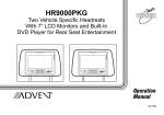
MMD850
OVERHEAD 8.5” TFT LCD
MONITOR
WITH BUILT-IN DVD PLAYER
Installation Guide
Important Notice
Installation of overhead products requires careful planning and preparation. Be
extremely careful when working on a vehicle with side curtain air bags. Do not
route wires near any portion of the side curtain air bag assemblies. This
includes any anchor points in A, B, C or D pillars of the vehicle. Routing wires
in these areas or running wires by the side curtain air bags can prevent the
side curtain air bag from fully deploying which can result in personal injury to
vehicle occupants. If you have any questions regarding wire routing in a
vehicle, please contact Audiovox Technical Support at 1-800-225-6074.
When connecting power and ground in a mobile video installation ensure that
the ACC wire is fused at the point where it is connected to the vehicle ACC
wiring. Failure to do so can result in damage to the vehicle if a short circuit
develops between the vehicle connection point and the mobile video product.
An LCD panel and/or video monitor may be installed in a motor vehicle and
visible to the driver if the LCD panel or video monitor is used for vehicle
information, system control, rear or side observation or navigation. If the LCD
panel or video monitor is used for television reception, video or DVD play, the
LCD panel or video monitor must be installed so that these features will only
function when the vehicle is in “park” or when the vehicle’s parking brake is
applied.
An LCD panel or video monitor used for television reception, video or DVD play
that operates when the vehicle is in gear or when the parking brake is not applied
must be installed to the rear of the driver’s seat where it will not be visible, directly
or indirectly, to the operator of the motor vehicle.
Licensed under one or more of the following patents, Patent NOS. 5,775,762 and
5,927,784
2
MATERIALS INCLUDED IN THIS PACKAGE
1)
2)
3)
4)
5)
Overhead 8.5” TFT LCD Monitor with DVD Player
Dome Light Harness (112B3110)
2 Pin Power Harness (112-3881)
Remote Control (136-4509)
Hardware Kit (150-1717):
• Screw, Pan Head, Philips
• Self Drilling Screw
• M5 Flange Nut
6) Trim Ring (102-4497)
7) Mounting Bracket (108-3981)
1)
2)
– 1pc
– 1pc
– 1pc
– 1pc
– 8pcs
– 4pcs
– 4pcs
– 1pc
– 1pc
3)
7)
4)
POWER
5)
SOURCE
MUTE
VOLUME
PIX
ENTER
PREV
NEXT
PAUSE
FR
PLAY
FF
STOP
SETUP
REPEAT
SUBTITLE
AUDIO
ZOOM
6)
DVD SOURCE DISC MENU DISPLAY
1
2
5
6
9
0
3
4
7
8
FMM ON/OFF CHANNEL SELECT
TOOLS REQUIRED:
•
•
•
•
•
•
•
•
•
•
•
3
#2 Phillips Screwdriver
#1 Phillips Screwdriver
Utility or Razor Knife or Shears
Wire Strippers
Upholstery hook tool (for removal of panels as necessary)
Electrical Tape
Masking Tape
Multimeter (to verify 12 volt DC and continuity: Do not use a test light or logic probe)
Marker pen – to mark headliner
Scribe (to mark trim ring if used)
Misc. electrical connectors (to connect to vehicle power source). Requirements will vary
from vehicle to vehicle.
WIRING DIAGRAM
Dome Light Harness
Violet/Brown
(Lamp Auto)
Red/Black
(Lamp On)
Black/Red
(Lamp Common)
FM ANT
Red: +12VDC Accessory Ckt.
(Install 5A inline Fuse)
Power Harness
AV Input Cable
Black: Ground
Line In-V (Yellow)
Line In-R (Red)
Line In-L (White)
AV Output Cable
Line Out-V (Yellow)
Line Out-R (Red)
Line Out-L (White)
1)
Connect the Power Harness to the mating connector on the Video Monitor.
2)
Connect the Power Harness to the vehicle's electrical system through an In-Line
5-Ampere fuse by tapping into an accessory hot line. Also connect the Black
wire to a good chassis ground.
3)
Connect the AV input cable to the AV Source output equipment ( VCD, Game, DVD Player etc)
4)
Connect the AV output cable to other AV Source input equipment.
5)
Verify all functions of the system before final mounting of the finished assembly.
4
GENERAL INSTALLATION APPROACH:
1) Decide upon system configuration and options that will be installed (i.e.: what components,
VCP, Video Game, external amp, wireless headphones, VCP, etc.).
2) Review all manuals to become familiar with electrical requirements and hook ups.
3) Decide upon mounting locations of all components and method of mounting.
4) Prep the vehicle by removing any interior trim necessary to gain access to vehicle's wiring
as well as all areas where interconnecting wire harnesses will need to be located. If any
access holes need to be cut into the vehicle (headliner, other trim components etc.), this
should be done now as well.
5) Route the wiring harnesses throughout the vehicle as necessary. (Refer to the Wiring
Diagrams on this manual as well as the wiring instructions for the individual components
and accessory options being installed). Be sure that all wiring is protected from sharp edges
and is routed in such a manner that pinched when all components and interior trim are fully
installed. Be sure to leave enough slack in the wiring at each component to allow working
room.
6) Remove all A/V system components from their packaging and place them loosely in the
vehicle at their respective locations.
7) Connect all components together (electrically) and verify proper operation of all system
functions.
Note: This is best done BEFORE, components have been permanently mounted.
8) After verifying proper operation of the system, proceed to mount of each component.
9) When all components are mounted, recheck function of entire system again to ensure that
no wiring was pinched or connected improperly during final installation.
VEHICLE PREPARATION:
1) Locate an accessory power source (+12v when key is in the ACC. and run positions,
and 0v when key is off), and also a good ground generally, these wires can be found at
the ignition switch or fuse-box.
2) The mounting method and location will vary from vehicle to vehicle, so this manual will
only focus on the installation of the ADV26 and related console accessories.
3) Generally, the best location for the video monitor is where the vehicle's factory dome
light is installed. The monitor should be located in such a manner that it can be
comfortably viewed by rear seat passengers.
NEVER INSTALL THE MONITOR IN A PLACE WITHIN THE DRIVER'S VIEW. THIS IS
NOT ONLY DANGEROUS, BUT IT IS ALSO ILLEGAL IN MANY STATES.
5
4) Once the mounting location of the monitor has been determined, there may be
additional preparation work necessary, depending on the vehicle structure and
installation method. Some of the steps that may be required are:
A) Removal of the vehicle's dome light
B) If the trim ring will be used, it may have to be trimmed to fit the contour of the
vehicle's headliner. Refer to the "Trim Ring Installation" section in this manual.
Mounting the Trim Ring
Roof
Roof Support
Headliner
Mounting Bracket
Self-drilling Screws
Trim Ring
Video Unit
M4 Flange Nut
CONNECTING THE DOME LIGHTS
The dome lights in the video monitor require three connections to the vehicle's wiring.
There are two common types of dome light circuits used, positive or negative switched.
Positive systems supply voltage to the interior lights to turn them on, negative switched
systems apply ground to illuminate the bulbs. To determine which system you have you
must locate the wires at the dome light. On a positive switched system, with all the
doors closed and the lights out, both wires at the dome light will rest at ground. When
the light is activated, one of these wires will switch to +12 vdc. This is the vehicle's
switching wire. On a negative switched system, with all the doors closed and the lights
out, both wires at the dome light will rest at + 12vdc. When the light is activated, one of
these wires will switch to ground. This is the switching wire.
For positive systems, connect the violet / brown (Lamp auto) wire to the vehicle's
switched wire. Then connect the red / black (lamp on) wire to a fused constant 12 volt
source and the black / red (lamp common) wire to a good ground. Positive systems are
commonly found on Ford vehicles.
6
For negative systems, connect the violet / brown (Lamp auto) wire to the vehicle's
switched wire. Then connect the red / black (lamp on) wire to a good ground and the
black / red (lamp common) wire to fused constant 12 volt source. Negative systems
are commonly found on General Motors and import vehicles.
Note: Some vehicles which incorporate transistorized control of the dome light
circuit, such as the 1999 Dodge Caravan, may require that the violet / brown (Lamp
auto) wire be connected to the door pin switch wire, as the additional current draw of
the Monitor's lights may not be supported by the output of the vehicles body control
computer.
Positive Switched Dome Lighting
To
constant
+12vdc
Red / Black – Lamp on
Black / Red – Lamp common
Violet / Brown – Lamp Auto
To 3 pin
connector
on Monitor
Factory Dome Light Circuit
To
constant
+12vdc
Factory Door ajar
switch or Body
Control computer
Negative Switched Dome Lighting
To 3 pin
connector
Red / Black – Lamp on
Black / Red – Lamp common
Violet / Brown – Lamp Auto
To
constant
To
constant
Factory Door ajar
switch or Body
7
© Copyright 2008 Audiovox Electronics Corporation, 150 Marcus Blvd., Hauppauge, NY, 11788
128-8238