1
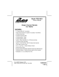
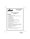
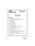
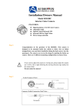
INSTALLATION GUIDE FOR:
Models CDC-FDN & CDC-FDW
CD CHANGER
INTERFACE CABLE
for 1998-99 FORD VEHICLES
Form No. 128-5399A
CAUTION: FOLLOW THE CONNECTION SEQUENCE DESCRIBED BELOW TO ENSURE PROPER
RECOGNITION OF THE CD CHANGER BY THE FACTORY RADIO.
DO NOT FORCE CONNECTORS TOGETHER. LINE UP LOCATING TABS AND CAREFULLY
MATE CONNECTORS.
INSTALLATION INSTRUCTIONS FOR THE CDC-FDW: (Fig. 1)
IMPORTANT : Installation must be done with vehicle and radio in OFF position.
1. Mount the CD Changer at the desired location in the trunk following the installation instructions supplied
with the CD Changer.
2. Carefully connect the 8-pin circular DIN connector from the CDC-FDW to the mating socket on the CD
Changer.
3. Route the CDC-FDW cable toward the existing factory CD Changer connector located in the trunk area.
4. With the vehicle off, carefully connect the CDC-FDW female connector to the male factory CD Changer
connector.
INSTALLATION INSTRUCTIONS FOR THE CDC-FDN: (Fig. 2)
IMPORTANT : Installation must be done with vehicle and radio in OFF position.
1. Mount the CD Changer at the desired location either in the center console (CDC-620 only) or in the rear of
the vehicle. Refer to the installation instructions supplied with the CD Changer.
2. Carefully connect the 8-pin circular DIN connector from the CDC-FDN to the mating socket on the CD
Changer.
3. Route the CDC-FDN cable toward the factory radio.
4. Remove the factory radio from the dash panel using the factory removal tools.
5. Unplug both the J1 power/speaker and the J3 CD Changer connector from rear of the factory radio.
6. Carefully connect the vehicle CD Changer J3 connector to the respective mating connector on the CDC-FDN
and CD Changer connector of the CDC-FDN to the respective mating connector at the rear of the radio.
7. Carefully reconnect the vehicle side J1 power/speaker connector to the mating connector at the rear of the
factory radio.
8. Depending on the application, connect the Black/Green wire to the ground tab on the back of the factory
radio chassis or splice wire to Pin #11 of the vehicle side J1 connector.
9. Either by splicing or using the T-tap provided, connect the Grey/Purple wire from the CDC-FDN to Pin #9
wire of the vehicle side J1 connector.
OPERATION CHECK:
1. Load CD's into the CD Changer cartridge and insert the cartridge into the changer.
2. Start vehicle and allow CD Changer to cycle.
Perform a brief functional test to verify proper operation according to the owner's manual.
© 1998 Audiovox Corporation, 150 Marcus Blvd., Hauppauge, N.Y. 11788
Printed in China
CDC-FDW Installation Diagram (Fig. 1)
6 OR 10 DISC CHANGER
VEHICLE CD CHANGER
DATA CONNECTOR
(LOCATED IN TRUNK)
CD CHANGER
DATA CONNECTOR
8-PIN DIN
CONNECTOR
CDC-FDW
CDC-FDN Installation Diagram (Fig. 2)
J1 CONNECTOR DETAIL
PIN
1
2
3
4
5
6
7
8
FACTORY RADIO REAR VIEW
.25" FEMALE
SPADE
TERMINAL
ILLUMINATION (+)
ILLUMINATION (-)
START (MUTE FOR CRANK)
CLOCK SET
RIGHT REAR (+)
RIGHT REAR (-)
RIGHT FRONT (+)
RIGHT FRONT (-)
9
+ 12VDC BATTERY MEMORY
10
+ 12VDC BATTERY ACC
11 CHASSIS GROUND
J3 CD CHANGER
DATA CONNECTOR
12
13
14
15
16
POWER /SPEAKER
CONNECTOR
GROUND
TERMINAL
(See Note)
FUNCTION
LEFT REAR (+)
LEFT REAR (-)
LEFT FRONT (+)
LEFT FRONT (-)
POWER AMP GROUND
J1 VEHICLE POWER/SPEAKER
CONNECTOR
(SEE J1 CONNECTOR DETAIL)
T-TAP OR SPLICE ONTO
WIRE AT PIN-9 LOCATION
BLACK w/GREEN STRIPE
GROUND WIRE
CDC-FDN
.25" MALE SPADE
TERMINAL PROVIDED
IN KIT
GRAY/PURPLE WIRE
CONSTANT 12 VOLTS
J3 VEHICLE
CD CHANGER
CONNECTOR
6 OR 10 DISC CHANGER
NOTE: For vehicles without ground terminal, splice Black w/Green stripe wire into Pin #11 of the vehicle side J1 connector.
FACE VIEW OF
CONNECTOR
8
1
16
9
PIN-9
WIRE COLOR
WILL VARY
WITH VEHICLE.