1
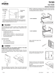
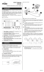
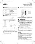
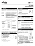
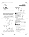
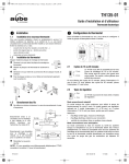
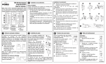
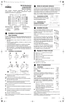
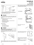
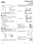
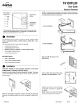
400-209-000-A (TH209) ENG.fm Page 1 Thursday, June 19, 2008 8:43 AM
TH209
User Guide
Electronic Thermostat
Heating intensity
indicator. No image
appears when
heating is off.
n
Connect any one of thermostat wires to the heater (load) wire and the
other one to the power supply wire using solderless connectors for
copper wires. (The thermostat wires are non-polarized; either wire
can be connected to the load or to the power supply.)
Temperature display
Up button
Down button
}
NOTE: All cables and connections must conform to the local electrical code. Special CO/ALR solderless connectors must be used when
connecting with aluminium conductors.
Temperature
adjustment
buttons
Description
1.
This thermostat can be used to control an electric heating system
such as a baseboard heater, a radiant floor,a radiant ceiling, or a convector.
2-wire installation
The thermostat CANNOT be used with:
•
•
•
•
•
a resistive load under 0.83 A
a resistive load over 8.3 A
a system driven by a contactor or a relay (inductive load)
a fan-forced heating system (e.g. : fan-forced convector)
a central heating system
SUPPLIED PARTS
•
One (1) thermostat
•
Two (2) 6-32 mounting screws
•
Two (2) solderless connectors
o
Installation
4-wire installation
2.
TURN OFF POWER OF THE HEATING SYSTEM AT THE MAIN
POWER PANEL TO AVOID ELECTRIC SHOCK.
Loosen the screw holding the faceplate to the base. The screw cannot be completely removed and remains captive on the base.
Remove the faceplate from the base by pulling the bottom half.
Install the base onto an electrical
box.
Reinstall the faceplate on the base
and secure it in place with the screw.
NOTE: Keep the air vents of thermostat clean and unobstructed at all
times.
TH209
400-209-000-A
2008-06-19
1/2
400-209-000-A (TH209) ENG.fm Page 2 Thursday, June 19, 2008 8:43 AM
p
Selecting the Temperature Format
3.
To select the temperature display format:
n
o
p
PROBLEM
Press the Up and Down buttons for three seconds.
The format currently used will be indicated on the
screen.
Press the Up or Down button to change the
format.
Press the Up and Down buttons for one second (or
wait for one minute) to return to the normal display.
q
Temperature Display and Setting
t
Troubleshooting
To view the setpoint temperature, press once on
either temperature adjustment button. The setpoint
will be displayed for 5 seconds. The icon
appears during the setpoint display.
•
To change the setpoint temperature, press the
appropriate button until the desired value is displayed.
This is normal. Under normal operation, the thermostat housing can reach a temperature
between 35 °C (95 °F) and 40 °C (104 °F).
Displayed temperature is wrong.
Remediate if any the following conditions
applies:
•
The thermostat is exposed to air draft.
•
The sticker on the thermostat’s screen has
not been removed.
•
The thermostat is located near or above a
heat source such as a light dimmer.
Display disappears
and reappears after
a few minutes.
The thermal protection device on the heater has
temporarily opened. This can happen if the
heater is obstructed by furniture or curtain and
has overheated, or if the heater’s thermal protection device is too sensitive.
4.
r
Power Outage
;
5.
During a power outage, the setpoint is saved in memory. You do not
need to adjust the temperature when power returns.
s
Specifications
- Supply: 120/240 VAC, 50/60 Hz
- Minimum load: 0.83 A (resistive only)
200 W @ 240 VAC
100 W @ 120 VAC
- Maximum load: 8.3 A (resistive only)
2000 W @ 240 VAC
1000 W @ 120 VAC
- Display range: 0 °C to 50 °C (32 °F to 122 °F)
- Setpoint range: 5 °C to 30 °C (40 °F to 85 °F)
- Storage: -20 °C to 50 °C (-4 °F to 120 °F)
- Heating cycle length: 15 seconds
- Approval:
6.
SOLUTIONS
Thermostat is hot.
The thermostat normally displays the actual (ambient) temperature.
•
7.
Warranty
8.
Aube warrants this product, excluding battery, to be free from defects in the
workmanship or materials, under normal use and service, for a period of three
(3) year from the date of purchase by the consumer. If at any time during the
warranty period the product is determined to be defective or malfunctions,
Aube shall repair or replace it (at Aube's option).
If the product is defective,
(i)
return it, with a bill of sale or other dated proof of purchase, to the place
from which you purchased it, or
(ii)
contact Aube. Aube will make the determination whether the product
should be returned, or whether a replacement product can be sent to
you.
This warranty does not cover removal or reinstallation costs. This warranty
shall not apply if it is shown by Aube that the defect or malfunction was
caused by damage which occurred while the product was in the possession of
a consumer.
Aube's sole responsibility shall be to repair or replace the product within the
terms stated above. AUBE SHALL NOT BE LIABLE FOR ANY LOSS OR
DAMAGE OF ANY KIND, INCLUDING ANY INCIDENTAL OR CONSEQUENTIAL DAMAGES RESULTING, DIRECTLY OR INDIRECTLY, FROM ANY
BREACH OF ANY WARRANTY, EXPRESS OR IMPLIED, OR ANY OTHER
FAILURE OF THIS PRODUCT. Some provinces, states or regions do not
allow the exclusion or limitation of incidental or consequential damages, so
this limitation may not apply to you.
THIS WARRANTY IS THE ONLY EXPRESS WARRANTY AUBE MAKES ON
THIS PRODUCT. THE DURATION OF ANY IMPLIED WARRANTIES,
INCLUDING THE WARRANTIES OF MERCHANTABILITY AND FITNESS
FOR A PARTICULAR PURPOSE, IS HEREBY LIMITED TO THE THREEYEAR DURATION OF THIS WARRANTY. Some provinces, states or regions
do not allow limitations on how long an implied warranty lasts, so the above
limitation may not apply to you.
This warranty gives you specific legal rights, and you may have other rights
which vary from one province, state or region to another.
Technical assistance
9.
705 Montrichard
Saint-Jean-sur-Richelieu, Quebec
J2X 5K8
Canada
Tel.: (450) 358-4600
Toll-free: 1-800-831-AUBE
Fax: (450) 358-4650
Email: [email protected]
For more information on our products, go to
www.aubetech.com
TH209
400-209-000-A
2008-06-19
2/2