1
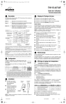
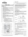
TH1 23
ELECTRONIC PROGRAMMABLE THERMOSTAT FOR HEATING AND COOLING
SYSTEMS
SUMMARY
TEMPERATURE SPAN ADJUSTMENT
Press PROG key while RETURN key is pressed in.
changes the span setting.
or
button
INTRODUCTION
This thermostat can replace most common residential thermostats
and is designed to be used with electric, gas or oil heating and air
conditioning systems using 24 volts control and relay current up to
1.0 ampere.
Several useful functions and operating modes have been incorporated to adapt a variety of customer needs: besides all the features
associated with the state of the art programmable thermostat, you’ll
find on TH123:
•
a 7 day timer to set the ECONO mode during a prolonged
absence.
•
a signal entry to remotely control the ECONO mode.
•
a protection against freezing.
•
a filter supervision.
•
a programmable regulation sensibility (SPAN).
To protect the compressor from damage and wear by cycling on
and off too rapidly, the TH123 incorporates a minimum five (5) minutes delay between cooling cycles.
If you have any questions concerning the installation or programming of the thermostat, please call our technical assistance at
1-800-831-AUBE or for the Montreal area, (450) 358-4600 from
8:30 AM to 5:00 PM, Monday through Friday, Eastern time.
INSTALLATION
This thermostat has been designed for simple and quick installation
requiring only a few tools.
TO SET TIME AND DAY
Press DAY, HOUR and MIN keys to adjust the time and day.
TO MODIFY HEATING AND COOLING PROGRAMS
•
•
•
Set the function switch to HEAT position for heating programs
and to COOL for cooling programs.
Use PROG key to select the program to be modified.
Use HOUR and MIN keys to set the time and
select the temperature setting.
or
button to
OPERATING MODES
AUTO:
executes the programs.
perature setting.
MAN:
bypasses the programming.
perature setting.
TIMER ECONO:
or
button shows the temor
changes the tem-
maintains the ECONOmic temperature setting
until a user presets time and day.
ECONO REMOTE: maintains the ECONOmic temperature setting
as long as an external signal is applied.
FILTER FUNCTION
Shows the number of hours that the system has operated since the
last filter change. Prevents freezing during your absence.
REQUIRED MATERIAL
•
•
•
•
Hammer
Masking tape
Drill and 3/16” drill bit
Phillips screwdriver
REMOVING YOUR OLD THERMOSTAT
WARNING: To avoid electric shock, turn off the power of the
heating and cooling system at the main power box in your home.
Read the following instructions carefully before disconnecting the
wires.
n Turn off your old thermostat.
o Remove the cover from the old thermostat. You may have to
pull extra hard.
p Unscrew the old thermostat from the wall plate
q Now find the screws attaching the wall plate to the wall, and
remove them. You should now be able to pull the wall plate a
small distance from the wall. Do not disconnect any wires yet,
simply locate the wires.
Note: If your old thermostat has only two (2) wires connected to it
(heating system only), simply disconnect the two wires from the wall
plate, skip over steps 1 and 2 in the Wire labelling section and go on
to step 3.
WARNING: After removing the wall plate, if you find that it is
mounted on a junction box (e.g. a box similar to one behind a light
switch or electric outlet), 240 volts circuit may be present and there
is a danger of electric shock. Please consult a qualified electrician.
WIRE LABELLING
n If your old thermostat wall plate has more than two wires connected to it, then you will need to label the wires. First look for
LETTER near each terminal where a wire is connected. These
terminals and markings may be on either side of the wall plate.
Disconnect and identify each wire.
o
p You may wish to tape the wires to the wall to keep them from
slipping through the hole in the wall. If the hole in the wall is
larger than necessary, fill it in order to prevent hot or cold air to
penetrate the thermostat. In this manner, the thermostat will
behave perfectly.
CHOOSING A LOCATION
q Turn on the main switch of the system. The thermostat is ready
for use.
WIRING DIAGRAM
The TH123 thermostat can be used with any single stage heating
and cooling system. You cannot directly use this thermostat on multiple stages heating or cooling system, millivolt system, heat pump
or 240 VAC control system. It can control some of those systems by
installing an isolation relay and a 24-volt transformer.
HEATING SYSTEM TYPE
The heating system type selector is located below the wire connector. Start first by keeping the selector at default position Hg. If the
fan switch is at FAN AUTO position and the fan doesn’t start when
the thermostat turns on the furnace, place the type selector at position He.
2-WIRE HEATING SYSTEM
Note: For a new installation, choose a mounting location about five
feet (150 cm) above the floor in an area with good air circulation and
away from:
Drafts or dead air spots, Air ducts, radiant heat from the sun or
appliances, Concealed pipes and chimneys.
Mounting the thermostat onto the wall
n Remove completely the slide door of the thermostat.
o Unscrew and remove the cover over the connector.
p Mark the holes posi-
q
r
tion and align the wire
coming from the wall
in the hole beside the
connectors.
Drill two holes and
insert the plastic
anchors carefully into
the holes until they are
flush with the wall.
Fasten securely the thermostat to the wall with the two (2)
screws.
n Connect the heating relay to terminal W.
o Connect the 24 VAC transformer to terminal Rh.
3-WIRE HEATING SYSTEM WITH FAN CONTROL
DISPLAY IN °C OR °F
After the installation of the battery, if
you want to change unit of the degree
displayed, follow these instructions
(see the illustration):
n From the back of the thermostat,
unscrew the cover.
o For the °C display, the jumper in
JP1 is installed.
p For the °F display, the jumper in JP1 is removed.
q Re-install the cover in place.
n Connect the heating relay to terminal W.
o Connect the fan relay to terminal G.
p Connect the 24 VAC transformer to terminal Rh.
4-WIRE HEATING AND COOLING SYSTEM
r Press on the reset button.
CONNECTING THE LABELLED WIRES TO THE THERMOSTAT
n Connect the system wires to the terminals according to the wiring diagram shown in the section “wiring diagram”.
WARNING: Do not remove the jumper between terminals Rh and
Rc unless otherwise specified.
o Push on the wires in the wall and replace the cover over the
connectors.
p Install two (2) “AA” size batteries into the battery compartment.
n
o
p
q
Connect the heating relay to terminal W.
Connect the cooling relay to terminal Y.
Connect the fan relay to terminal G.
Connect the 24VAC transformer to terminal Rh.
5-WIRE HEATING AND COOLING SYSTEM
your thermostat will operate without batteries, it is recommended to
replace the batteries when the display is showing “BATT”.
OPERATING MODES
The thermostat has four (4) operating modes: AUTOmatic, MANual,
TIMER ECONO and REMOTE ECONO.
AUTO
The AUTOmatic mode executes in sequence (hourly)
the recorded programs.
Ͽ
Ͽ
WARNING: Remove jumper between terminals Rh and Rc: Both 24
volts returns of the transformers must be connected together in
order to have the fan working with the heating and the cooling
system. *Otherwise, the fan will only work with the cooling system.
*(both transformer supplies, 120/240 vac, must be the same).
n Connect the heating relay to terminal W.
o
p
q
r
Connect the cooling relay to terminal Y
Connect the fan relay to terminal G.
Connect the 24VAC heating transformer to terminal Rh.
Connect the 24VAC cooling transformer to terminal Rc.
REMOTE ECONO MODE
Connect the auxiliary system (alarm or domotic system for instance)
between the terminals X (positive) and C (negative). The signal
from those systems must be 12 to 24 VAC or VDC.
Press on the AUTO button. The “PROG” icon and
the running program will be displayed.
Pressing
or
button displays the temperature set point of the running program for five (5) seconds.
MAN
The MANual mode allows the user to bypass the programming.
Ͽ
Ͽ
Press on the MAN button. The
displayed.
icon will be
A first pressing on
or
displays the MAN
temperature set point. Each subsequent pressing will change
the MAN temperature set point by 0.5°C (1°F).
TIMER ECONO
The TIMER ECONO mode holds the ECONO temperature set point until user predetermined
time and day is reached. Then, the thermostat turns to
AUTOmatic mode.
This operating mode avoids the user to reprogram his
thermostat for a prolonged absence (up to one week)
and allows for maximum savings.
Ͽ
Ͽ
Ͽ
Ͽ
To get into this operating mode, press and hold MAN button for
three (3) seconds.
The
icon, the return time and the ECONO temperature set
point will be displayed.
Press DAY, HOUR and MIN keys to specify the return time.
Press
point.
or
button to specify the ECONO temperature set
REMOTE ECONO
An auxiliary system as your alarm or domotic system for instance,
can turn your thermostat to ECONO mode. The thermostat holds
the ECONO temperature set point as long as the signal of the auxiliary system is applied.
The
icon is flashing to indicate that the auxiliary signal is
present.
When the auxiliary signal is removed, the thermostat returns to the
previous operating mode (see wiring diagram).
FIRST POWER-UP
FUNCTION SWITCH
When power is applied for the first time, the display
must show time and day as well as the ambient
temperature as follows:
If the display is different, press the RESET button.
Use a fine probe such as straightened paper clip to
gently push the RESET button.
This switch selects the functions: HEAT, COOL, and OFF.
HEAT:
Select that position to control the heating system. In
AUTO mode, the thermostat will refer to heating programs to control the temperature.
Note: Your thermostat is using two (2) “AA” size
batteries to protect its memory against a power failure. Even though
COOL:
Select that position to control the cooling system. In
AUTO mode, the thermostat will refer to cooling programs to control the temperature.
OFF:
This function shuts off the heating and cooling systems.
This function holds the temperature setpoint at 5°C
(40°F) (heating) in order to prevent freezing. It is not
programmable.
FILTER:
The thermostat keeps a record of the number of hours
your filter has been used. It will display the total number
of hours the system has used the filter from the moment
the filter was replaced and that the filter counter was
reset to zero. After 250 hours of system operation, the
FILTER indicator will begin flashing, to remind you to
change or clean the filter and to reset the filter counter
back to zero. The filter counter will count up to a maximum 999 hours and stays there until you reset it again.
To reset the counter, press and hold the FILTER key
until the display shows 000.
PROGRAMMING SCHEDULE
Use following programming schedule as a memorandum before
programming or changing a program by writing down your schedule
of heating and cooling.
Weekday programs (Mon.... Fri.)
Temperature Setpoints
Prog
Hour
Heating
Cooling
1
2
3
4
Weekend programs (Sat.& Sun.)
1
PROGRAMMING
2
The thermostat has an automatic return. When functions such as
the time recording, the program recording, etc. have not been completed by pressing the RETURN key, the thermostat will automatically exit those functions after five (5) or ten (10) seconds.
TIME AND DAY ADJUSTMENT
n Press DAY, HOUR and MIN to adjust the time
and day.
o Press RETURN or wait five (5) seconds for
TEMPERATURE SPAN ADJUSTMENT
The factory set temperature span is 1°C (2°F). For example, if the
temperature set point is 20°C (68°F), the heating system will turn on
at 19.5°C (67°F) and turn off at 20.5°C (69°F).
This span is programmable. You can choose between 0.5°C (1°F),
1°C (2°F), 1.5°C (3°F) and 2°C (4°F).
To review or to change the temperature span:
n Press PROG while RETURN key is maintained.
o Release both keys.
p Press or to select the new span.
q Press RETURN or wait 10 seconds the automatic
automatic return.
PRE-RECORDED PROGRAMS
This thermostat has four (4) preprogrammed heating and cooling
programs for weekday and two (2) for weekend. They can be used
as is or you can modify them at your convenience.
Weekday programs (Mon.... Fri.)
Temperature Setpoints
Prog
Hour
Heating
Cooling
1
6:00 AM
21°C (70°F)
23°C (73°F)
2
8:30 AM
21°C (70°F)
23°C (73°F)
3
4:00 PM
21°C (70°F)
23°C (73°F)
4
11:00 PM
17°C (63°F)
27°C (80°F)
Weekend programs (Sat.& Sun.)
1
6:00 AM
21°C (70°F)
23°C (73°F)
2
11:00 PM
17°C (63°F)
27°C (80°F)
PROGRAMMING MODIFICATION
return
Note: Choosing a small temperature span such as 0.5°C (1°F) will
be more comfortable (less temperature variation in the apartment)
but in counter part, the heating or the cooling system will turn on
and off more often.
CHARACTERISTICS
Model: TH123
Supply: 24 VAC, 50 / 60 Hz
Load: 1 amp maximum
Auxiliary input: 12 to 24 Volts AC/DC
Numbers of programs: 4 weekday programs and 2 weekend
programs
Storage temperature range: -20°C to 50°C (0°F to 120°F)
Operating temperature range: 0°C to 50°C (32°F to 120°F)
n Place function switch to HEAT position for heating programs or COOL for cooling programs.
o Press the PROG key. The display shows the program’s starting time and temperature setpoint.
The Monday to Friday indicators are turning on
showing that this program is associated to the
days of the week. The program number 1 is flashing to indicate the selected program.
Pressing again PROG key will scroll weekday programs 1 to 4
and weekend programs 1 and 2
Select program to be modified using PROG key.
p
q Press HOUR and MIN keys to modify program’s starting time
and
or
buttons to modify program’s temperature setpoint.
r Press RETURN key or wait 10 seconds for automatic return.
AUBE TECHNOLOGIES INC. ONE (1) YEAR LIMITED WARRANTY
This product is warranted against material defects and workmanship in normal
use for a period of one year, from the date of the original purchase from
authorized dealers. Warranty does not cover transportation costs. Nor does it
cover a product subjected to misuse or accidental damage. This limited warranty
is in lieu of all other warranties, obligations or liabilities expressed or implied by
the company. In no event shall AUBE Technologies inc. be liable for
consequential or incidental damages resulting from installation of this product.
Within this period, any product proven defective in normal use will be repaired or
replaced at AUBE's option, without charge for either parts or labour, provided that
the defective product with the original sale receipt is returned to the original
dealer or is shipped prepaid, insured and addressed to:
AUBE TECHNOLOGIES INC.
Service centre
705, Montrichard Avenue
Saint-Jean-sur-Richelieu (Quebec)
Canada J2X 5K8
(450) 358-4600 or 1-800-831-2823