1
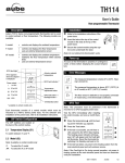
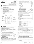
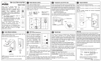
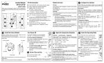
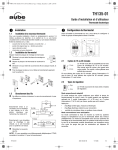
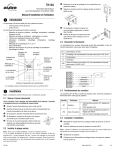
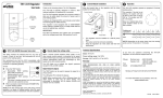
MODEL TH111GFCI-NP 120 VAC
SUMMARY
OPTIONS SELECTION
At the back of the thermostat, there is one selection switches to set at
your preferences.
Temperature in °C or °F.
TO SET TEMPERATURE
(COMFORT) SETPOINT TEMPERATURE
Select chosen setpoint temperature by using
or
button (2 to 3 seconds) until icon appears on display.
TO RECORD THE
TO RECORD THE
button. Press on
(ECONOMIC) SETPOINT TEMPERATURE
Select chosen setpoint temperature by using
or
button (2 to 3 seconds) until icon appears on display .
This thermostat was designed to control floor electric heating systems. The
resistive load must not exceed 2000 watts @ 120 VAC (16.7 A). The
thermostat is equipped with a ground fault circuit interrupter (GFCI) and
therefore the isolation of the line and load is required for operation. The
polarity of line connection must be respected. During a ground fault, only the
current in the black wire of the load will be cut-off from the 120 V line.
Connect thermostat as shown on diagram.
1) CONNECTING WIRES AND MOUNTING THERMOSTAT
Press on
or
once to see setpoint temperature appear on display. Every
subsequent press will change the setpoint temperature by one degree.
TO RECORD THE
This thermostat should be installed by an electrician or experienced technician.
The thermostat must be used with a circuit breaker or fuse.
Connect the rear thermostat wires to the power supply and to the load using
solderless connectors for copper wires. See schematic diagram.
Push the excess wire back into the electrical box to prevent interference
withthe thermostat. Secure the thermostat using two (2) 6-32 screws
1 1/4 inches long. Once the thermostat is properly installed, return power
to heating system.
button. Press on
(VACATION) SETPOINT TEMPERATURE
To program the Vacation temperature, select the desired degree using the
buttons and press on the
and
buttons simultaneously until the
icon is displayed (app. 3 seconds).
CHECKING GROUND FAULT CIRCUIT INTERRUPTER (GFCI)
Adjust the setpoint temperature until heating indicator (flames) appears on
display. Press TEST button. The test is conclusive if the warning light (GFCI) on
thermostat is ON and power to the load is cut-off (flames remain on display
though). If these events do not occur, check the installation. Press on RESET button to reset the GFCI.
2) CONNECTING TEMPERATURE SENSOR WIRE
Connect the sensor wire to the two lower screws of the terminal block at the
back of the thermostat (no polarity need to be respected). The wire must pass
outside the electrical box and follow the wall down to the floor. The sensing
probe should be placed in a representative heat area for maximum system
perfomance. The sensing probe should be centered between the wires in the
mat. The probe wire cannot cross any heater wires and the temperature sensor
must not be directly or adjacent to a heating wire.
120 VAC
INSTALLATION
Parts included:
One (1)
Two (2)
Four (4)
One (1)
60 HZ
TH111GFCI-NP (120 VAC) thermostat
6-32 screws
Solderless connectors (for copper wire)
Temperature sensor with a 15 foot extension
TURN OFF POWER TO THE HEATING SYSTEM AT THE MAIN POWER
PANEL TO AVOID ELECTRICAL SHOCK. KEEP AIR VENTS OF THE
THERMOSTAT CLEAN AND OBSTRUCTION FREE.
CHOOSING THE TEMPERATURE SCALE IN °C (CELSIUS) OR °F
(FAHRENHEIT) TO APPEAR ON DISPLAY.
Set the temperature switch at the back of the thermostat to °C or °F at your
preferences.
720-111715-B 1/2
POWER UP
• Recording a setpoint temperature for the
To power up thermostat:
Select chosen setpoint temperature by using
and
buttons. Keep
pressing on the
button (2 to 3 seconds) until icon appears on display.
• Recording a setpoint temperature for the
(VACATION) setting
When power is applied for the first time,
the display must show the time 00:00,
the floor temperature and the manual
mode icon (
). Other information
might show up on the display if installation is defective or does not comply with
the instructions. The warning light (GFI)
must be off.
To program the Vacation temperature, select the desired degree using the
buttons and press on the
and
buttons simultaneously until the
icon is displayed (app. 3 seconds).
The message L0 or HI will appear on
the display if the temperature sensor is
defective or the temperature is below 0
°C (32 °F) or higher than 60 °C (140
°F). Also, the heating indicator will be
present on display and the relay will be
closed (current going in the load).
Once stored, the setpoint temperatures can be recalled simply by selecting the
or
button or both
and
for
setpoint.
CHECKING GROUND FAULT CIRCUIT INTERRUPTER (GFCI)
Adjust the setpoint temperature until
heating indicator (
) appears on
display. Press TEST button. The test is
conclusive if the warning light (GFCI)
on the thermostat is ON and power to
the load is cut-off. If these events do not
occur, check the installation. Press on
RESET button to reset the GFCI.
If the GFCI test fails:
Check the load wires. The thermostat
must be in heating mode to carry out
the test (heating indicator ON).
The GFCI test should be carried out
monthly. If the test fails, cut off
the electric power to the heating
system and call customer service or
return the thermostat to your supplier
for verification. If the warning light
comes on during normal operation, cut
off power to the heating system and
have an electrician verify the installation.
OPERATION
The thermostat has 4 different buttons to control the floor temperature. The
and
buttons increase or decrease the setpoint temperature. The
and
buttons are used to store and recall two temperature settings.
• Default values
To erase the recorded setting temperatures (
and
) and replace their values by the default ones,
28 °C (82 °F) and 18 °C (64 °F) press the
button while pressing and releasing the RESET button. Then release the
button.
• Setting a setpoint temperature
Press once the
or
button to see the setpoint temperature on display. Every
subsequent press will change the setpoint temperature by one degree.
• Recording setpoint temperature for
(VACATION) settings
(ECONOMIC) setting
(COMFORT) ,
(ECONOMIC) and
By recording the setpoint temperatures you will be able to go from the
setting to the or
setting by simply pressing the
or button or ( and
) for
.
• Recording a setpoint temperature for the
(COMFORT) setting
Select chosen setpoint temperature by using
and
buttons. Keep
pressing on the
button (2 to 3 seconds) until icon appears on display.
NOTE: When the temperature setting used is
or or
, you can still use
the
or
buttons to change the setpoint temperature without changing the
recorded temperature.
• Recalling stored setpoint temperatures
CHARACTERISTICS
Model:
TH111GFCI-NP (120 VAC)
Supply:
120 VAC, 50/60 Hz
Load:
16.7 A maximum (resistive only)
Power:
2000 watts @ 120 VAC
Ground fault circuit interrupter (GFCI):
Class A (5 MA TRIP LEVEL)
Approvals:
CSA/C, US
Display range:
0 to 60 ºC (32 °F to 140 ºF)
Setting range:
5 °C to 40 ºC (40 °F to 104 ºF)
Default setting:
28 °C (82 °F)
Default setting:
18 °C (64 °F)
Storage:
-20 °C to 50 ºC (-4 °F to 120 ºF)
Temperature regulation:
1 ºC (2 °F)
Precision:
± 0.5 ºC (1 °F) (2000 W)
WARRANTY
AUBE TECHNOLOGIES INC. ONE (1) YEAR LIMITED WARRANTY
This product is warranted against material defects and workmanship in
normal use for a period of one year, from the date of the original purchase from
authorized dealers. During this period, AUBE technologies inc. will repair or
replace the product with a new or of equivalent quality at AUBE'S option,
without charge, any product proven defective in normal use.
Warranty does not cover transportation costs. Nor does it cover a product
subjected to misuse or accidental damage. This warranty does not cover the cost
of installation, removal or reinstallation.
This limited warranty is in lieu of all other warranties, obligations or liabilities
expressed or implied by the company. In no event shall AUBE technologies inc.
be liable for consequential or incidental damages resulting from
installation of this product. Some states or provinces do not allow limitations on
how long an implied warranty lasts, or the exclusion or limitation of
incidental or consequential damages, so the above exclusions or limitations may
not apply to you.This warranty gives you specific legal rights and you may also
have other rights which vary from state to state.
The defective product and the original sale receipt must be returned to the
original dealer or shipped pre-paid, insured and addressed to:
•Aube technologies inc. • Customer Service • 705, Av. Montrichard
• Iberville (Quebec) • J2X 5K8
If you have any questions concerning the installation or programming of this
product, please call our technical assistance at (450) 358-4600 for the Montreal
area or
1-800-831-AUBE for outside area, Monday to Friday between
8:30 AM and 5:00 PM Eastern time.
09/03/01
720-111715-B 2/2