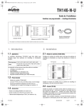
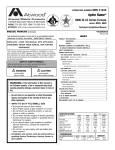
1
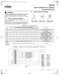
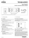
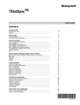
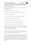
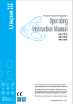
LITERATURE NUMBER MPD 31230 hydro flame TM 8900-III-LD 2 Stage Series Furnace 9 2540 Technical Installation Manual MODEL Patent No US 6,464,000. 6,719,207. Other Patents Pending ENGLISH, FRANCAIS •Installation (et Canada) Effective 1/08 THIS INSTRUCTION MANUAL IS FOR USE BY AN AUTHORIZED SERVICE TECHNICIAN TO INSTALL AN ATWOOD - hydro flame TM INDEX FURNACE. ..............................................................1 ..................................................................1 WEIGHT ........................................................................1 MINIMUM CLEARANCE TO FLOORBOARDS, WALLS, & SIMILAR COMBUSTIBLE BUILDING MATERIALS ..............................1-2 SAFETY INFORMATION ..................................................................1-2 FURNACE INSTALLATION ..................................................................2 WALL CUTOUT OPTIONS HORIZONTAL & VERTICAL ......................................2 VENT INSTALLATION (MODELS WITHOUT DOOR) HORIZONTAL & VERTICAL ................2 DUCTING HORIZONTAL & VERTICAL ....................................................2-3 Required Minimum Discharge Chart ............................................3 Flexible Ducting ......................................................................3 Floor Ducting ........................................................................3 OPTIONAL INSTALLATION - BOTTOM DISCHARGE KIT ..................................3 PROPANE GAS CONNECTION ............................................................3 ELECTRICAL CONNECTIONS ..............................................................3 Conductor Sizing Table ............................................................3 Thermostat Installation ..........................................................3-4 SYSTEM CHECK TESTS ....................................................................4 DIAGNOSTIC CHART ......................................................................4 PROPANE GAS PRESSURE ..............................................................4 STATIC PRESSURE ........................................................................4 WIRING DIAGRAM ..........................................................................4 ILLUSTRATIONS ............................................................................5 REPLACEMENT PARTS LIST & DRAWING ..............................................6 FURNACE SPECIFICATIONS DIMENSIONS INSTALLER: LEAVE THIS MANUAL WITH APPLIANCE. CONSUMER: RETAIN THIS MANUAL FOR FURTHER REFERENCE. This furnace design has been certified for installation in recreation vehicles as a MSP Category III furnace. Follow this installation instruction to insure safe operation of the furnace. Failure to install furnace according to this installation instruction nullifies the furnace warranty. SAFETY ALERT SYMBOLS Safety Symbols alerting you to potential personal safety hazards. Obey all safety messages following these symbols. WARNING avoid possible injury or death CAUTION avoid possible injury and/or property damage WARNING: If the information in this manual is not followed exactly, a fire or explosion may result causing property damage, personal injury or loss of life. — Do not store or use gasoline or other flammable SPECIFICATIONS vapors and liquids in the vicinity of this or any other appliance. MODEL • Evacuate all persons from vehicle. • Shut off gas supply at gas container or source. • Do not touch any electrical switch, or use any phone or radio in vehicle. • Do not start vehicle’s engine or electric generator. • Contact nearest gas supplier or qualified Service Technician for repairs. • If you cannot reach a gas supplier or qualified Service Technician, contact the nearest fire department. • Do not turn on gas supply until gas leak(s) has been repaired. Installation and service must be performed by a qualified Service Technician, Service Center or gas supplier. (W.C. = Water Column) HIGH LOW BTU Input Duct Static Pressure 12 Volt Amperage (AMPS) Watts Power Supply (VOLT DC) Recommended Return Air MINIMUM RETURN AIR — WHAT TO DO IF YOU SMELL GAS — 2540 25,000 .10˝ W.C. 7.2 86 12 80 in2 80 in2 40,000 .10˝ W.C. 16.8 202 12 80 in2 80 in2 DIMENSIONS ALL MODEL Casing Door Recess Bezel VENT WEIGHT WIDTH HEIGHT DEPTH 16-1/2˝ 19-1/4˝ 20-9/16˝ 5˝ 9-1/8˝ 9-1/4˝ 11-1/2˝ 5-3/8˝ 23 1/2˝ - 26˝ 1/4˝ 39 lbs 46 lbs FURNACE SHIPPING MINIMUM CLEARANCE TO FLOORBOARDS, WALLS & SIMILAR COMBUSTIBLE BUILDING MATERIALS MUST BE PROVIDED THE FULL LENGTH AND WIDTH OF UNIT 1 HORIZONTAL TOP VERTICAL TOP ----1/2˝ ----1/2˝ BOTTOM BOTTOM 3/16˝ ----0˝ SIDES SIDES ----1˝ ----1˝ REAR REAR --1/2˝ --1/2˝ Spacing of 1/4˝ to ducting within 3 feet of furnace must be provided unless UL listed wire bound vinyl ducts are used. All ducting material should be rated for continuous use at 200˚F. NOTE: Clearances are specifically for plywood or similar building materials surrounding the furnace (i.e. furnace should NOT be located under furniture or in a closet space where clothing or other material could be located.) NOTE: Furnace efficiency rating is a thermal rating determined under continuous operating conditions, independent of any installation. Efficiency rate is given at 77% minimum, actual efficiency rating may be higher. WARNING CARBON MONOXIDE POISONING • Properly seal vent assembly to prevent carbon monoxide from entering coach. • DO NOT draw combustion air from living area. DO NOT vent exhaust air into the living area or an enclosed porch. Return air is supplied through openings in furnace casing. All return air passages must be kept clear for furnace to function properly. Refer to MINIMUM CLEARANCE TO FLOORBOARDS, WALLS & SIMILAR COMBUSTIBLE BUILDING MATERIAL. The total unobstructed return air opening size(s) must NOT BE LESS than specified in SPECIFICATIONS - MINIMUM RETURN AIR. Failure to meet minimum return air requirements nullifies furnace warranty. WARNING CARBON MONOXIDE POISONING • Furnace must be installed and vented to these instructions. • Improper installation, adjustment, alteration, service or maintenance can cause injury or property damage. • Improper installation location may cause furnace to produce negative pressure, affecting combustion air or venting of other appliances. STANDARD FURNACE INSTALLATION General Installation - LOCATION Install furnace through an exterior wall. install furnace near tilt-out rooms, slide-outs, doors or other projections that could obstruct furnace exhaust. • Locate furnace near midpoint of coach for single furnace applications. • DO NOT install vent in areas where projections or door openings are within 6˝ of vent tube opening. • DO NOT install furnace in an area where wires, pipes, or other objects will interfere with installation or operation of furnace. • It is not recommended to install furnace on material that restricts return air, such as carpeting, or soft material such as vinyl. • DO NOT directly install furnace on carpeting or soft material, install furnace on cleats, or on a wood or metal panel extending the full width and depth of furnace plus minimum clearances to combustibles. • DO NOT use petroleum or citrus type cleaners on plastic parts, as damage may occur. • The furnace must always be installed level (front to back, side to side) to prevent water intrusion into the interior. • • DO NOT CRITICAL INSTALLATION WARNINGS install furnace on material that restricts return air, such as carpeting or any soft material i.e. vinyl. • DO NOT install furnace where clearance to combustibles cannot be maintained. • DO NOT modify furnace in any way. • Installation must provide accessibility if any repairs are necessary to the furnace. Failure to meet this requirement will create additional labor costs that will be the responsibility of the installer. • DO NOT alter furnace for a positive grounding system. • DO NOT HI-POT furnace unless electronic ignition system (circuit board) has been disconnected. • DO NOT use battery charger to supply power to DC model furnace even when testing. • DO NOT use 120 volt AC current with DC models. • DO NOT use furnace cabinet area as a storage compartment. • DO NOT vent furnace with venting system serving another appliance. • DO NOT vent furnace to an outside enclosed porch area. • DO NOT use for temporary heating of buildings or structures under construction. • Protect building materials from degrading from flue gas exhaust. • Protect furnace electrical components from water. • DO NOT USA AND CANADA WALL CUTOUT OPTIONS RECOMMENDED WALL THICKNESS DO NOT OVERSIZE HOLE HORIZONTAL & VERTICAL 0˝ to 2-1/2˝ - OVERSIZING CAN RESULT IN WATER LEAKAGE EXTERIOR WALL CUTOUT (FIG 1 -1A) HORIZONTAL & VERTICAL A 3-1/8˝ B C 2-3/8˝ 3-1/2˝ dia. hole VENT INSTALLATION HORIZONTAL & VERTICAL INSTALLATION (FIG 1-1A) 1. Locate vent hole cutout as called out in FIG 1-1A. 2. Drill 3-1/2˝ diameter hole through side wall of coach. 3. Remove vent and vent ring from furnace. 4. Insert furnace from backside of wall. Line up hole in wall with hole for vent to furnace. 5. Apply sealant to back of vent ring and vent cap base. 6. Install vent assembly with HOT at top for horizontal and on right side for vertical installation (FIG 1-1A). Slip into combustion air intake tube. Secure to wall with four (4) screws. 7. Vent assembly must have a minimum of 1-1/4˝ overlap on exhaust and 1/2˝ minimum on combustion air. 8. Horizontal units - secure to floor with two (2) screws through legs on back of casing. Vertical units use vertical mounting brackets and self-tapping screws to hold furnace to floor (tabs on control box can be used also to secure furnace). - FOLLOW ALL APPLICABLE STATE AND LOCAL CODES - IN THE ABSENCE OF LOCAL CODES OR REGULATIONS, REFER TO CURRENT STANDARDS OF: Recreation Vehicles ANSI A119.2/NFPA 501C. National Fuel Gas Code ANSI Z223.1 and/or CAN/CGA B149 Installation Codes • Federal Mobile Home Construction & Safety Standard, Title 24 CFR, part 3280, or when this Standard is not applicable, the Standard for Manufactured Home Installations (Manufactured Home Sites, Communities and Set-Ups), ANSI A255.1 and/or CAN/CSA-Z240 MH Series, Mobile Homes. • Ground-National Electrical Code ANSI/NFPA No. 70 and/or CSA C22.1 • Park Trailers ANSI A119.5 • • DUCTING HORIZONTAL & VERTICAL (FIG 2-3A) HORIZONTAL PROPER DUCT INSTALLATION IS CRITICAL TO THE OPERATION OF THIS FURNACE NOTE: The direct high voltage spark ignition generates a radio frequency that could cause interference with other microprocessor based equipment. Locate equipment at least five feet (5’) from furnace location. If this distance cannot be maintained, purchase KIT MPD 37773 (a shielded high voltage lead). CONTINUOUS USE MATERIALS RATING DUCTS 9˝ IN LENGTH OR MORE 4˝ DUCTS -LESS THAN 9˝ IN LENGTH METAL BOOTS LESS THAN 9˝ IN LENGTH 2 200˚F. 250˚F. 250˚F. Ducting systems can include any combination of discharge openings, as long as static pressure and minimum discharge area requirements are met. PROPANE GAS CONNECTION (FIG. 2) 1. Connect gas line to fitting on top rear of furnace. Be sure all male pipe threads, other than flare fittings, are treated with a sealing compound resistant to the action of propane (LP) gas. DO NOT put sealing compound on flare fittings. 2. A 3/8˝ flared fitting connection is provided at gas control valve inlet for gas supply connection to furnace. The gas supply line of the furnace must be of adequate size to provide 11˝ W.C. gas pressure. This pressure must be maintained under maximum flow conditions with all gas appliances in operation. 3. Use two wrenches to hold fitting and flare nut when tightening gas line to fitting. DO NOT twist fittings (FIG. 2). ALL MODELS - (also see STATIC PRESSURE TEST) 48 IN2 80 IN2 REQUIRED MINIMUM DISCHARGE REQUIRED MINIMUM RETURN AIR See MINIMUM CLEARANCE TO FLOORBOARDS, WALLS & SIMILAR COMBUSTIBLE BUILDING MATERIALS. • Each 4-inch duct opening provides 12 in2 of discharge area. Provide an extra 12 in2 of non closeable duct discharge area for each closeable register used. • Use of 2˝ ducts does not count toward achieving minimum discharge requirements. Ducting in dead air space with no return air, such as holding tank areas, does not count toward achieving minimum discharge requirements. • Adjust ducting installation to obtain air rise of 100˚F-130˚F. • ELECTRICAL CONNECTION WARNING INJURY OR PROPERTY DAMAGE • Label all wires before disconnecting for servicing. Wiring errors can cause improper and dangerous operation. Verify proper operation after servicing. • Disconnect electrical power before servicing. Flexible Ducting Systems When designing Flexible Duct Systems: • avoid sharp bends or crushed ducts • stretch all ducts and run them directly to outlets, keeping quantity and angles of bends to a minimum 1. Remove knockout plates from desired outlets. 2. Attach a duct adapter to each opening, by inserting flange over casing, locking the tab into casing slot and turning adapter 90˚. 3. Attach and secure FOUR-INCH flexible ducts to adapters. 4. Run ducts to desired location within RV, secure to registers. 5. Additional ducting may be needed to maintain correct static pressure. Conductor Sizing Table - MAX. 10% VOLTAGE DROP - (12 VDC) CURRENT DRAW (AMPS) 3 GAGE 18 16 14 57 87 Floor Hard Ducting Systems A 18-20 1/2˝ B 5-1/2˝ 7 8 9 10 15 16 43 65 34 52 29 43 25 37 21 33 52 19 29 46 17 26 41 11 17 28 21 This furnace is designed for negative ground 12 volts DC only. DO NOT attempt to alter furnace for a positive ground system or connect the furnace directly to 120 volts AC. Damage to furnace components will occur and warranty will be voided. Use a minimum of 14 GA wire to minimize voltage drop. Furnace must be installed so electrical components are protected from water. To make electrical connections see wiring diagram FIG. 4. 1. Route wiring to left side of furnace. 2. Connect red wire to positive side of power supply. 3. Connect yellow wire to grounded side of power supply. 4. Connect blue wire to thermostat using 22-18 GA stranded wire. 5. Connect the green wire to the green thermostat lead using minimum 22-18 GA stranded wire. See instruction with thermostat for complete wiring directions. For best furnace performance when power supply is from a converter equipped with a charging port, wire converter to furnace parallel with battery. This provides consistent voltage to furnace, increasing component life, filtering power surges and AC spikes. Each unit ships with a standard field harness connection with 12˝ wire leads. NOTE: All units are supplied with a power switch which when turned off for servicing will remove power through furnace wiring. Switch must be in ON position for furnace to operate FIG 2-G. - BOTTOM DISCHARGE (FIG 4) HORIZONTAL-WITHOUT DOOR (FIG 4) 6 PROPERTY DAMAGE • This connection is for low-voltage battery or direct current only. Do not connect to 120- or 240- volts AC. 1. Remove bottom discharge cover plate. This ducting option must be connected to a ducting system. FIG 3 (parts breakdown) #40 GASKET AND PLENUM PLATE KIT is available when attaching furnace. 2. If cutout is required: FLOOR CUTOUT BOTTOM DISCHARGE 5 CAUTION When designing Hard Ducting Systems: • undersize ducting will cause high temperature limiting • oversize ducting will cause inadequate air flow from registers • when hard ducting is 1-1/2˝ in depth, an additional flex duct may be needed to maintain installation static requirements • DO NOT install floor registers within 2 feet of return air openings. OPTIONAL INSTALLATION 4 MAX. LENGTH OF SAE CONDUCTOR (IN FEET) FROM SOURCE TO DEVICE C D 10-1/2˝ 3/4˝˝ 3. Fasten plenum plate (3-E) over floor cutout. If a gasket and plenum plate are not used, seal furnace to hard duct system making sure seal is air-tight and continue with STEP 5. 4. Position gasket (3-F) on plenum plate. 5. Set furnace on gasket, make sure gasket remains in position. 6. Additional ducting can be used to maintain correct static pressure. VERTICAL There is only one ducting option when using vertical installation. Option 1 has already been illustrated, the other configuration is using top two ducts and two ducts off the back of the casing. This is the only configuration allowed with vertical installation (FIG 3A). POWER SUPPLY Atwood Mobile Products highly recommends the use of an electronic (solid state) converter with clean, clear power output. This will assure the life of the electronic controls and motor life could be extended as much as 500% beyond typical linear converter applications. 3 THERMOSTAT INSTALLATION (MODEL 2H2C) FURNACE - MODEL 2540 MUST USE THIS THERMOSTAT NOTE: The thermostat is very sensitive. HANDLE WITH CARE AT ALL TIMES. Locate thermostat 48˝ to 54˝ above floor on an INTERIOR wall. Pick a dry area where air circulation is good. EXTERIOR wall location must have a 3/4˝ spacer between thermostat and exterior wall. 1. Be sure all electrical power has been disconnected from the air conditioner, furnace and the power supply. 2. Do not install the thermostat where there are unusual heating conditions: such as direct sunlight, heat producing appliances (television, radio, wall lamp, etc.) or a furnace or air conditioner supply register. 3. ATTACHING THE WALL THERMOSTAT. Separate the thermostat body from the sub-base by gently squeezing the top and bottom. Pull wires through access hole in base plate. Attach thermostat sub-base to the wall at the desired mounting location. Mount the sub-base to the wall before connecting the wires. See instruction provided with thermostat. PROPANE GAS PRESSURE TEST The furnace and any individual shut-off valve must be disconnected from gas supply piping system during any pressure testing of system at test pressures of more than 1/2 PSI. Before furnace is connected piping systems must be tested to be leak free. The test must maintain air pressure of at least 6˝ of mercury or 3 PSI for at least 10 minutes. The entire piping system must be maintained within a range of 10-14˝ W.C. when all appliances are in operation. Test gas connections for leakage with a leak test solution. STATIC PRESSURE TEST CASING STATIC PRESSURE TABLE If duct static pressure cannot be set, casing static pressure should not exceed the values listed below when taken cold. SYSTEM CHECKS WARNING FIRE OR EXPLOSION • Never check for leaks with an open flame. A diagnostic LED is located inside the exterior access cover on the outside edge of the horizontal (2) stage control board. The following graph defines the codes. DIANOSTIC INFORMATION 1 2 3 4 5 DUCTING SYSTEM OPERATING VOLTS FLEXIBLE HARD DC MODELS 12 0.25˝ W.C. 0.35˝ W.C. Voltage greater than indicated will cause higher static readings. Reducing the number of duct turns and stretching ducts will increase air flow and reduce static pressure. Adding ducts or increasing discharge system (hard ducting) will also reduce static pressure. NOTE: Special tool required to take casing static pressures. Location for Static Pressure Tap for casing is on the back of casing (top left corner) (FIG 3). DIAGNOSTIC CHART NUMBER OF LED FLASHES A SOFT lockout is a condition that is timed and will make additional attempts to correct the problem. A HARD lockout requires reset of the thermostat or turning the power switch off then back on. LOCKOUT Low Input voltage Ignition Failure Open High Limit Stuck Sail Switch Module Fault SOFT SOFT SOFT HARD HARD 2-STAGE - MODEL 2540 WIRING 4 ELECTRONIC DIGITAL THERMOSTAT MOTOR RED BLACK YELLOW RED +12 VDC +THERMO -12 VDC -THERMO WHITE DUAL CONTROL 1 1 RED WHITE BLACK 2 2 BLUE 5 5 YELLOW GREEN 6 6 BULK HEAD CONNECTOR ELECTRODE CHASSIS GROUND 6 5 4 3 21 3 3 4 4 IGNITION CONTROL SAIL SWITCH HIGH TENSION ORANGE BLUE YELLOW RED BROWN LIMIT SWITCH CHASSIS GROUND CUSTOMER SUPPLIED WIRE IMPORTANT: If any original wire has to be replaced, it must be replaced with type 105˚C or it's equivalent. 4 VALVE AVANT DU VEHICULE 1-A 1 B C A TE LE MUST USE Gas Line (Conduite de gaz) OU RIE TSID UR E DU RV VE HIC U ) G 3 3-A 2 MU U ST MU F E 4 D A C MUST USE (EX Casing Static Check Point B 5 SE U ST SE hydro flame TM 8900-III-LD 2 Stage Series Furnace Model 2540 42 8 32 53 56 52 20 22 1 15 OFF COOL HEAT FAN 49 41 28 23 43 58 36 M 35 6 48 26 50 54 10 37 17 24 9 12 19 57 DRAWING 1 6 8 9 10 15 17 19 20 22 23 24 26 28 32 35 36 37 41 42 43 48 49 50 52 # DESCRIPTION Blower Wheel Burner Assembly ON/OFF Switch / Circit Breaker Valve Coil Replacement (DC) Combustion Wheel Dual Thermostat Valve Vent Assembly Electronic Ignition Board Duct Adapters Duct Cover Plate Electrode Adapter Plate Assembly High Tension Lead Limit Switch Motor Gasket Motor Orifice - #49 Sail Switch Element Assembly Exhaust Wall Gasket Blower Housing Back Blower Housing Motor/Combustion Wall Control Board Mounting Bracket 53 54 55 56 57 58 Motor Speed Control Board Adapter Plate Burner Access Cover (specify) Extended Manifold Vent Ring Gas Line Gasket N˚ SUR LE SCHÉMA 1 6 8 9 10 15 17 19 20 22 23 24 26 28 32 35 55 DESCRIPTION Ventilateur Brûleur Interrupteur MARCHE/ARRÊT/Coupecircuit Echange du serpentin de la vanne (CC) Ventilateur d'air de combustion Double thermostat Soupape Assemblage de ventilation Panneau d'allumage électronique Adaptateurs de conduit Couvercle d'ouverture de branchement de conduit Électrode Plaque adapatatrice de flexibles Fil haute tension Rupteur thermique Joint d'étanchéité du moteur 6 36 37 41 42 43 48 49 50 52 53 54 55 56 57 58 59 Moteur Orifice - # 49 Interrupteur à abattant Elément de chauffage Joint entre le système d'évacuation et la paroi Arrière du boîtier du ventilateur Boîtier du ventilateur Paroi moteur/ventilateur d'air de combustion Support de fixation du tableau de commande Panneau de commande de vitesse du moteur Plaque adaptatrice Burner Access Cover (à spécifier) Distributeur Anneau Joint d’étanchéité du tuyau à gaz