1
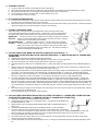
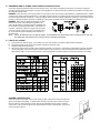
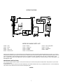
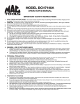
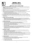
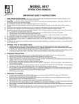
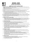
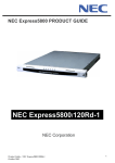
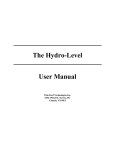
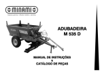
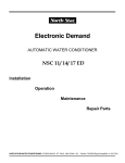
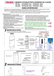
MODEL BC-9400A
OPERATOR'S MANUAL
IMPORTANT SAFETY INSTRUCTIONS
1.
SAVE THESE INSTRUCTIONS. This manual contains important safety and operating instructions for battery charger you have
purchased. You may need to refer to these instructions at a later date.
CAUTION. To reduce risk of injury, charge only wet cell, lead-acid, automotive type rechargeable batteries. Other types of batteries may
burst causing personal injury and property damage.
3. Do not expose the charger to rain or snow if specifically warned on the unit not to do so.
4. Use of an attachment not recommended or sold by the battery charger manufacturer may result in a risk of fire, electric shock, or injury to
persons.
5. To reduce the risk of damage to the electric plug and cord, pull by the plug rather than the cord when disconnecting the charger.
6. Make sure the cord is located so that it will not be stepped on, tripped over, or otherwise subjected to damage or stress.
7. An extension cord should not be used unless absolutely necessary. Use of a improper extension cord could result in a risk of fire and electric
shock. If an extension cord must be used, make sure:
a. That the pins on the plug of extension cord are the same number, size, and shape as those of the plug on the charger;
b. That the extension cord is properly wired and in good condition; and
c. If the length of the extension cord is less than 25 feet, use a 16AWG cord, If 50 feet- 12AWG, 100 feet-10AWG, 150 feet-8AWG.
8. Do not operate the charger with a damaged cord or plug, replace them immediately.
9. Do not operate the charger if it has received a sharp blow, been dropped, or otherwise damaged in any way; take it to a qualified serviceman.
10. Do not disassemble the charger unless you are qualified to work on electrical products. If not, take it to a qualified serviceman when service or
repair is required. Incorrect reassembly may result in risk of electric shock or fire.
11. To reduce the risk of electric shock, unplug the charger form the outlet before attempting any maintenance or cleaning. Turning off the controls
will not reduce this risk.
2.
12. WARNING - RISK OF EXPLOSIVE GASES
a. WORKING IN VICINITY OF A LEAD-ACID BATTERY IS DANGEROUS. BATTERIES GENERATE EXPLOSIVE GASES DURING NORMAL
BATTERY OPERATION. FOR THIS REASON IT IS OF UTMOST IMPORTANCE THAT EACH TIME BEFORE USING YOUR CHARGER, YOU
READ THIS MANUAL AND FOLLOW THE INSTRUCTIONS EXACTLY.
b. To reduce the risk of battery explosion, follow these instructions and those published by the battery manufacturer and manufacturer of
any equipment you intend to use in vicinity of the battery. Review cautionary markings on these products and on the engine.
13. PERSONAL PRECAUTIONS
a. Someone should be within range of your voice or close enough to come to your aid when you work near a lead-acid battery.
b. Have plenty of fresh water and soap nearby in case battery acid contacts skin, clothing, or eyes.
c. Wear complete eye protection, and clothing protection. Avoid touching eyes while working near battery.
d. If battery acid contacts skin or clothing, wash immediately with soap and water. If acid enter eyes, immediately flood eyes with running
cold water for at least 10 minutes and get medical attention immediately.
e. NEVER smoke or allow a spark or flame in vicinity of the battery or engine.
f.
Be extra cautious to reduce risk of dropping a metal tool onto the battery. It might spark or short circuit the battery or other electrical parts
that may cause an explosion.
g. Remove personal metal items such as rings, bracelets, necklaces, and watches when working with a lead-acid battery. A lead-acid
battery can produce a short circuit current high enough to weld a ring or the like to metal, causing a severe burn.
h. Use this charger for charging a LEAD-ACID battery only. It is not intended to supply power to a low-voltage electrical system other than in
an automotive application. Do not use this battery charger for charging dry-cell batteries that are commonly used with home appliances.
These batteries may burst and cause injury to persons and damage to property.
i.
NEVER charge a frozen battery.
14. PREPARING TO CHARGE
a. If necessary to remove battery from vehicle to charge, always remove the grounded terminal from the battery first. Make sure all
accessories in the vehicle are off, so as not to cause an arc.
b. Be sure the area around the battery is well ventilated while the battery is being charged. Gas can be forcefully blown away by using a
piece of cardboard or other non-metallic material as a fan.
c. Clean the battery terminals. Be careful to keep corrosion from coming in contact with eyes.
d. Add distilled water in each cell until battery acid reaches level specified by the battery manufacturer. This helps purge excessive gas from
cells. Do not overfill. For a battery without cell caps, carefully follow the manufacturer's recharging instructions.
e. Study all battery manufacturer's specific precautions such as removing or not removing the cell caps while charging and the recommended
rates of charge.
f.
Determine voltage of the battery by referring to the car owner's manual and make sure that the output voltage selector switch is set at the
correct voltage. If the charger has adjustable charge rate, charge the battery initially at the lowest rate.
1
15. CHARGER LOCATION
a. Locate the charger as far away from the battery as the DC cables permit.
b. Never place the charger directly above the battery being charged; gases from the battery will corrode and damage the charger.
c. Never allow battery acid to drop on the charger when reading the specific gravity or filling battery,
d. Do not operate the charger in a closed-in area, or restrict ventilation in any way.
e. Do not set a battery on top of the charger.
16. DC CONNECTION PRECAUTIONS
a. Connect and disconnect the DC output clamps only after setting the charger switches to the OFF position and removing the AC cord from
the electric outlet. Never allow the clamps to touch each other.
b. Attach the DC clamps to the battery post and twist or rock back and forth several times to make a good connection. This tends to keep the
clamps from slipping off the terminals and helps to reduce the risk of sparking.
17. STOP/GO LITE INSTRUCTIONS
When used properly, the STOP/GO LITE will indicate whether clamp connections will be correct.
Connect the positive (red) clamp to the positive (POS, P, +) battery post. Touch the contact button of
the negative (black) clamp to the other battery post. Observe the L.E.D. lights in the STOP/GO LITE:
GREEN LIGHT:
The first connection is correct. Make the second clamp connection per instructions.
RED LIGHT: The first connection made with the positive clamp to the battery is incorrect. Attach the
positive clamp to the other battery post and retest.
RED AND GREEN LIGHT:
The battery charger is turned on. Turn the charger "OFF" and retest.
NO LIGHT:
Check for a shorted or open battery. Clean any corrosion from the clamp jaws and the
battery post and retest. If still no light, use a voltmeter or other means to make certain
you have properly identified the polarity of the battery post. Then attach the clamps per
instructions, disregarding the STOP/GO LITE.
18. FOLLOW THESE STEPS WHEN THE BATTERY IS INSTALLED IN A VEHICLE. A
SPARK NEAR THE BATTERY MAY CAUSE A BATTERY EXPLOSION. TO REDUCE THE RISK OF A SPARK NEAR
THE BATTERY:
a.
b.
c.
d.
e.
f.
g.
h.
i.
Read the section "STOP/GO LITE INSTRUCTIONS" before proceeding.
Position the AC and DC cords to reduce the risk of damage by the hood, door, or moving engine parts.
Stay clear of fan blades, belts, pulleys, and other parts that can cause injury to persons.
Check the polarity of the battery post. The POSITIVE (POS, P, +) battery post usually has a larger diameter than the NEGATIVE (NEG, N, -)
post.
Determine which post of the battery is grounded (connected) to the chassis. If the negative post is grounded to the chassis (as in most
vehicles), see item "e". If the positive post is grounded to the chassis, see item "f".
For negative-grounded vehicles, connect the POSITIVE (RED) clamp from the battery charger to the POSITIVE (POS, P, +) ungrounded post
of the battery. Touch the contact button of the STOP/GO LITE to the NEGATIVE (NEG, N, -) battery post. Interpret the light and take
appropriate action. When the green light is on, connect the NEGATIVE (BLACK) clamp to the vehicle chassis, heavy gauge metal part of
the frame, or engine block, away from the battery. Do not connect to the carburetor, fuel lines, or sheet metal body parts.
For positive-grounded vehicles, connect the POSITIVE (RED) clamp from the battery charger to the POSITIVE (POS, P, +) battery post.
Touch the contact button of the STOP/GO LITE to the NEGATIVE (NEG, N, -) battery post. Interpret the light and take appropriate action.
When the green light is on, disconnect the POSITIVE (RED) clamp from the battery. Attach the NEGATIVE (BLACK) clamp to the NEGATIVE
(NEG, N, -) ungrounded post of the battery. Attach the POSITIVE (RED) clamp to the vehicle chassis or engine away from the battery. Do
not connect the clamp to the carburetor, fuel lines, or sheet-metal body parts. Connect to a heavy gauge metal part of the frame or engine
block.
When disconnecting the charger, turn the switches to OFF, disconnect the AC cord, remove the clamp from the vehicle chassis, and then
remove the clamp from the battery terminal.
See the operating instructions for length of charge information.
19. FOLLOW THESE STEPS WHEN THE BATTERY IS OUTSIDE THE VEHICLE. A SPARK NEAR THE BATTERY MAY
CAUSE BATTERY EXPLOSION. TO REDUCE THE RISK OF A SPARK NEAR THE BATTERY:
a.
b.
c.
d.
e.
f.
g.
h.
Read section "STOP/GO LITE INSTRUCTIONS" before proceeding.
Check the polarity of the battery post. The POSITIVE (POS, P, +) usually has a larger diameter than
the NEGATIVE (NEG, N, -) post.
Attach at least a 24 inch long 6-gauge (AWG) insulated battery cable to the NEGATIVE (NEG, N, -)
battery post.
Connect the POSITIVE (RED) charger clamp to the POSITIVE (POS, P, +) post of the battery.
Touch the contact button of the STOP/GO LITE to the free end of the battery cable. If the red light
comes on, reverse the connections to the battery and retest. When the green light come on, position yourself and the free end of the
cable as far away from the battery as possible, then connect the NEGATIVE (BLACK) charger clamp to the free end of cable.
Do not face the battery when making the final connection.
When disconnecting the charger, always do so in reverse sequence of connecting procedure, and break the first connection while
standing as far away from the battery as practical.
A marine (boat) battery must be removed and charged on shore. To charge it on board requires equipment specially designed for marine
use.
2
20. GROUNDING AND AC POWER CORD CONNECTION INSTRUCTIONS
The charger should be grounded to reduce the risk of electric shock. This charger is equipped with an electric cord having an equipment
grounding conductor and a grounding plug. The plug must be plugged into an outlet that is properly installed and grounded in accordance with
all local codes and ordinances.
DANGER. Never alter the AC cord or plug provided - if it will not fit the outlet, have a proper outlet installed by a qualified electrician. Improper
connection can result in a risk of an electric shock. This battery charger is for use on a nominal 120-volt circuit, and has a grounding plug that
looks like the plug illustrated in FIGURE (A). A temporary adapter, which looks like the adapter illustrated in FIGURE (C), may be used to connect
this plug to a two-pole receptacle, as shown in FIGURE (B), until a properly grounded outlet can be installed by a qualified electrician.
DANGER. Before using an adapter as illustrated, be certain
that the center screw of the outlet plate is grounded. The
green-colored rigid ear or lug extending from the adapter must
be connected to a properly grounded outlet - make certain it is
grounded. If necessary, replace the original outlet cover plate
screw with a longer screw that will secure the adapter ear or
lug to the outlet cover plate and make ground connection to
grounded outlet.
NOTE:
USE OF AN ADAPTER IS NOT ALLOWED IN CANADA. IF A GROUNDING TYPE RECEPTACLE IS NOT AVAILABLE, DO NOT USE THIS
APPLIANCE UNTIL THE PROPER OUTLET IS INSTALLED BY A QUALIFIED ELECTRICIAN.
21. LENGTH OF CHARGE
a. Test the battery for state of charge. Do not charge if it is over 75% charged or the battery is determined to be defective.
b. Set beginning amps charge rate for size of battery and state of charge per charts
c. Charge for length of time per charge,
d. Discontinue charge when the specific gravity of electrolyte reaches 1.260 or above. A temperature compensating hydrometer should be
used for this reading. Discontinue charge if the battery begins to gas excessively or when the temperature of the electrolyte reaches
approximately 120EF. Do not overcharge batteries. Overcharging results in excessive water loss and eventual damage to the battery.
ASSEMBLY INSTRUCTIONS
Attach the handle to the charger using the four screws provided. Attach the front leg to the base with
the four hex head screw provided. To attach wheels and axle to the base, tap one axle nut onto the
axle with a hammer, slide one wheel onto the axle with the whitewall facing out, place one washer
onto the axle, Push the axle through the base, place washer and wheel on opposite side. Tap axle nut
onto the axle with a hammer.
3
OPERATING INSTRUCTIONS
CAUTION - This battery charger must be fully assembled before operating. Failure to do so may result in risk of injury.
USE OF INSTRUMENT PANEL:
The MINUTES CHARGE timer has an OFF position, a CONTINUOUS CHARGE position and a timed charge range from 0 to 90 minutes.
a. OFF - Always make sure the timer is in the OFF position before connecting or disconnecting the clamps from the battery. The charger will
not charge with the timer in this position.
b. 0 to 90 MINUTES TIMED CHARGE - The timer will automatically turn the charger off at the end of the pre-set charging time. Turn the timer
past 20 before setting the desired time.
c. CONTINUOUS CHARGE - This position is used for slow charging or parallel charging, the timer will not shut the charger OFF while in this
position. Do not use this position for fast charging.
TO CHARGE BATTERIES
Make the connections to the battery per the instructions in the previous sections.
Determine if the battery is 6 or 12 volts and then set the CHARGE VOLTAGE switch to 6 CHARGE for a 6 volt battery or 12 CHARGE/BOOST for
a 12 volt battery. Turn the timer on. The Ammeter will show the amount of current delivered to the battery. Length of charge should be per the
above chart and instructions.
BOOST STARTING
Turn off all lights and accessories in the stalled vehicle.
Connect the charger to battery per previous instructions. Charge the battery for at least five minutes before attempting to start the vehicle. Put
the switch in the 12 CHARGE/BOOST position.
Start the vehicle with the charger connected to the battery. Follow the duty cycle on the unit.
NOTE: Do not crank the engine more than 20 seconds in any five minute period; excessive cranking may overheat and damage the starter.
If the vehicle fails to start, while waiting for the starter to cool, allow the charger to continue to charge the battery.
Turn the switch to OFF and remove the AC power cord from the electric outlet before disconnecting the DC clamps.
CHARGING SULFATED BATTERIES
If your battery has sat in the discharged state for an extended period of time, it can become SULFATED. This usually is seen as a white deposit
near the top of the battery. The sulfate is formed when a battery with low water levels remains discharged for an extended time. Sulfated
batteries exhibit the characteristic of accepting no charge regardless of the rate of charge.
The charging method is two staged. The first stage of attempting to break down the sulfation to allow the battery to accept a charge must be
closely watched to avoid excessive charge rates as the battery begins to charge and overheating. The second stage is a slow charging to
restore the battery to full charge.
READ AND FOLLOW ALL PRECAUTIONS AND WARNINGS IN YOUR INSTRUCTION MANUAL BEFORE ATTEMPTING TO CHARGE SULFATED
BATTERIES. FAILURE TO OBSERVE THESE WARNINGS MAY RESULT IN PROPERTY DAMAGE OR SERIOUS PERSONAL INJURY OR DEATH.
To recharge a sulfated battery:
1. Attach the battery clamps as described in the instruction manual.
2. Always use the chargers lowest rate when turning the charger on. Set the charger to the chargers highest rate for the voltage of
the battery being charged.
CAUTION: NEVER CHARGE A BATTERY AT VOLTAGES RATES ABOVE THAT OF THE BATTERY.
3.
The battery will show little or no amperage at the start of the charging process. This will continue until the sulfation begins to break
down.
CAUTION: AS THE SULFATION BREAKS DOWN, THE AMPERAGE MAY RAPIDLY RISE. CONSTANT ATTENTION
MUST BE OBSERVED TO PREVENT SERIOUS OVERHEATING OF THE BATTERY.
4.
5.
NOTE:
Lower the charge rate to the lowest rate for the voltage of battery being charged.
Charge the battery at this low rate until the electrolyte reaches the fully charged state as described in the tables in your instruction
manual. This may take as long as two or three days.
SOME BATTERIES MAY BE SO BADLY SULFATED THEY CAN NOT BE RESTORED TO A NORMAL OPERATING CONDITION,
REGARDLESS OF THE RATE OF CHARGE OR THE LENGTH OF TIME THE CHARGE IS APPLIED. IF THE BATTERY CANNOT BE
RESTORED TO A FULLY CHARGED CONDITION BY A SLOW CHARGING, IT SHOULD BE REPLACED.
4
WIRING DIAGRAM
MODEL BC-9400A PARTS LIST
610389
610277
605671
610052
605672
Timer
Switch
Leg
Axle w/nuts
Wheels w/nuts
610392
610391
610189
610190
610281
Rectifier
Transformer
Fan Blade
Fan Motor
DC Circuit Breaker
610278
610282
605677
610283
Amps Charge Meter
AC Cord
DC Cable Set
Handle
Parts may be purchased from your local authorized service depot listed in the Service Procedure manual supplied with your product. If you elect to
order parts from the factory you may do so by mail or phone. Minimum order from the factory is $25.00. Orders received that are under the minimum
will not be processed. Taxes and freight are extra and are not considered to be part of the dollar value of the order. We do not have a C.O.D.
policy. Cashier check, Money order, Mastercard or VISA are acceptable. If you use a Mastercard or VISA send only the number and expiration. DO
NOT SEND THE CARD.
MAINTENANCE INSTRUCTIONS
Worn clamps and jaws should be replaced. Worn parts can lead to poor connections and present a safety hazard. See parts list for part number
of jaw and clamp kits.
Any Maintenance or repair of this unit that involves disassembly of the cabinet should be done only by a qualified serviceman. Incorrect reassembly
may result in a risk of electric shock when the unit is subsequently used.
NOTES:
5
W????
Rev. ??/?? 027-0518
6
8400A ENGLISH MANUAL
ILLUSTRATION LISTING 27-523E.MAN
FIG.
1
2
3
4
5
6
7
FILE NAME
LOGO.EPS
STOP-GO.WPG
EXT-BAT.WPG
PLUG-ENG.PLT
ENGLSTBL.PLT
8400CAB.TIF
8400WR-e.PLT
DESCRIPTION
ASSOCIATED LOGO
STOP GO LITE ON BATTERY-ENGLISH
EXTERNAL BATTERY W/LEAD EXTENSION
GROUNDING ADAPTER -ENGLISH
CHARGE RATE TABLE - ENGLISH
8400A CABINET
8400A WIRING DIAGRAM - ENGLISH
7