1
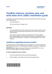
Revised Edition V2
December 2014
E9955
VivoMini memory, wireless card, and
solid state drive (SSD) installation guide
Your VivoMini comes with the following items. Please contact ASUS Service Center if you cannot
find the following items:
•
4 pcs holed rubber foot
•
3 pcs 3mm round screws, 1 hexagon screw
IMPORTANT!
•
It is recommended that you install or upgrade the memory modules, wireless card, and
solid state drive (SSD), under professional supervision. Visit an ASUS service center for
further assistance.
•
Ensure that your hands are dry before proceeding with the rest of the installation
process. Before installing any of the features in this guide, use a grounded wrist strap or
touch a safely grounded object or metal object to avoid damaging them due to static
electricity.
Installing or upgrading memory modules
Your VivoMini comes with two SO-DIMM memory slots that allow you to install two 2GB, 4GB, or
8GB unbuffered with non-ECC 1.35 V DDR3 204-pin SO-DIMMs for a maximum of 16GB memory.
IMPORTANT! Refer to http://www.asus.com for the list of compatible DIMMs. You can only
install 1.35 V DDR3 SO-DIMM to the VivoMini’s DIMM slots.
To install or upgrade the memory modules:
1.
Turn off your VivoMini then disconnect all cables and peripherals.
2. Place the VivoMini on a flat stable surface, with its top side facing down.
15060-47900100
1
3.
Remove the four screws securing the cover.
4.
Get one screw from the ones you previously removed then place it into the hole. Leave
a portion of the screw head that would be enough for you to hold.
5.
Hold the screw then gently pull out the cover from the bottom side of the VivoMini. Use
your other free hand to hold the VivoMini in place.
2
6.
Align and insert the memory module into the slot (A) and press it down (B) until it is
securely seated in place. Repeat the same steps to install the other memory module.
IMPORTANT! Always install into the lower slot first.
7.
Remove the screw you previously attached on the bottom cover.
8.
Place the cover back on the bottom side of your VivoMini. Note that the cover can only
be inserted in one direction. Refer to the following illustration and note to ensure that
the cover is securely fitted on the bottom side of the VivoMini.
IMPORTANT! The rating
label area (A) and the
power button’s location
(B) must be oriented as
shown.
3
9.
10.
Reattach the screws to secure the cover back on the bottom side of the main box.
Place the rubber foot on each screw hole. Refer to the illustration for more details.
IMPORTANT! A number is printed under each rubber foot and this number corresponds
to that rubber foot’s location on the cover. Follow the orientation of each rubber foot
and the number sequence shown in the illustration below. The rubber foot fits in only
one orientation. Note the position of the hole on each rubber foot, as shown in the
illustration below
NOTE: If you want to remove the rubber foot, use a flathead screwdriver or a
straightened paper clip to do so.
4
Installing or upgrading the wireless card
Your VivoMini includes a mini-PCIe slot for half-size wireless and Bluetooth adapters.
Refer to http://www.asus.com for the list of compatible wireless and Bluetooth adapters.
To install or upgrade the wireless card:
1.
Follow steps 1-5 on pages 1-2 under the Installing or upgrading memory modules section
of this guide to remove the bottom cover of your VivoMini.
2.
Align and insert the wireless card into the lower slot inside the VivoMini. Refer to the
illustration for its location.
3.
Gently push down the wireless card on top of the screw holes and fasten it using two of
the 3mm round screws.
5
4.
Connect the black antenna to MAIN or
and the white antenna to AUX or
to the illustration for the right installation procedure.
. Refer
NOTE: A soft clicking sound indicates that the antenna has been securely attached on
the wireless card.
5.
Follow steps 7-9 on pages 3-4 under the Installing or upgrading memory modules section
of this guide to replace the bottom cover back on your VivoMini.
Installing or upgrading the mSATA SSD
Your VivoMini includes a PCIe slot that supports a full-size or a half-size mSATA SSD.
To install or upgrade a full-size mSATA SSD:
1.
6
Follow steps 1-5 on pages 1-2 under the Installing or upgrading memory modules section
of this guide to remove the bottom cover of your VivoMini.
2.
Align and insert the full-size mSATA SSD into its the upper slot inside the VivoMini. Refer
to the illustration for its location.
3.
Gently push down the mSATA SSD on top of the screw hole and fasten it using one of
the 3mm round screw. Refer to the illustration for the location of the screw hole.
4.
Follow steps 7-9 on pages 3-4 under the Installing or upgrading memory modules
section of this guide to replace the bottom cover back on your VivoMini.
To install or upgrade a half-size mSATA SSD:
1.
Follow steps 1-5 on pages 1-2 under the Installing or upgrading memory modules section
of this guide to remove the bottom cover of your VivoMini.
7
2.
Insert the hexagon screw into its corresponding hole, as illustrated. 3.
Align and insert the half-size mSATA SSD into its upper slot inside the VivoMini. Refer to
the illustration for its location.
4.
Gently push down the mSATA SSD on top of the screw hole and fasten it using one of
the 3mm round screw. Refer to the illustration for the location of the screw hole.
5.
Follow steps 7-9 on pages 3-4 under the Installing or upgrading memory modules section
of this guide to replace the bottom cover back on your VivoMini.
8