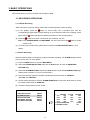
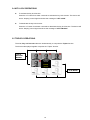
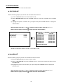
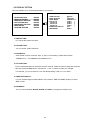
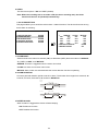
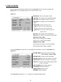
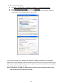
1
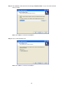
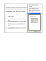
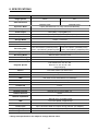
INSTALLATION &
OPERATION MANUAL
Digital Video Recorder
DVR-3704T
Before trying to connect or operate this product, please read this manual completely
SAFETY PRECAUTIONS
All the following safety and operation instructions for the prevention of harm or damage to the
operator or other persons should be read before the unit is operated.
WARNING
To reduce the risk of fire or electric shock, do not expose this appliance to rain or moisture.
Do not block ventilation openings.
Do not place anything on top of the unit that might spill or fall into it.
Do not attempt to service this unit yourself as opening or removing covers may expose you to
dangerous voltage or other hazards. Please refer all servicing to qualified service personnel.
Do not use liquid cleaners or aerosols for cleaning.
This installation should be done by a qualified service person and should conform to all local
codes.
To prevent fire or electric shock, do not overload wall outlets or extension cords.
This unit must be grounded to reduce the risk of electric shock hazard.
CAUTION
HDD:
Please don’t use the hard disk(s) you have employed with a particular model of the DVR (in
recording and playing back data) with any other model of DVR, for you will lose the data you have
stored in the hard disk(s) if you do so. You are free to use the same hard disks between DVRs
belonging to a single model.
Danger of explosion if the Lithium battery (RTC Battery) is incorrectly replaced.
Danger of explosion if battery is incorrectly replaced. Replace only with the same or
equivalent type recommended by the manufacturer. Dispose of used batteries according to
the manufacturer’s instructions.
Risk of explosion if replaced by an incorrect type. Dispose of used batteries according to the
instructions.
INFORMATION
This equipment has been tested and found to comply with the limits for a Class B digital device,
pursuant to Part 15 of the FCC Rules. These limits are designed to provide reasonable protection
against harmful interference when the equipment is operated in a commercial environment. This
equipment generates, uses, and can radiate radio frequency energy and, if not installed and used in
accordance with the instruction manual, may cause harmful interference with radio communications.
Operation of this equipment in a residential area is likely to cause harmful interference in which case
the user will be required to correct the interference at his own expense.
1
Table Of Contents
1. PRODUCT FEATURES .................................................................................................. 4
1.1 PRODUCT INTRODUCTION ...................................................................................................4
1.2 PRODUCT FEATURES .............................................................................................................4
2. DESCRIPTION OF THE FRONT/REAR VIEW............................................................... 6
2.1 FRONT VIEW.............................................................................................................................6
2.2 REAR VIEW ...............................................................................................................................9
2.3 ALARM In/Out .........................................................................................................................10
3. BASIC OPERATIONS .................................................................................................. 11
3.1 RECORDING OPERATIONS .................................................................................................. 11
3.1.1 Manual Recording .......................................................................................................................................... 11
3.1.2 Alarm Recording ............................................................................................................................................ 11
3.1.3 Timer Recording............................................................................................................................................. 12
3.2 PLAYBACK OPERATIONS......................................................................................................13
3.2.1 Fast Forward/Reverse..................................................................................................................................... 13
3.2.2 Playback Picture-by-picture ........................................................................................................................... 13
3.3 BACKUP OPERATIONS .........................................................................................................14
3.4 KEY LOCK OPERATIONS ......................................................................................................15
3.5 TRIPLEX OPERATIONS .........................................................................................................15
4. SEARCH MODE ........................................................................................................... 16
4.1 RECORD LIST .........................................................................................................................16
4.2 ALARM LIST ............................................................................................................................16
4.3 TIME FILTER ..........................................................................................................................17
5. MENU MODE ............................................................................................................... 18
5.1 QUICK SETTING ....................................................................................................................19
5.2 DISPLAY OPTION...................................................................................................................20
5.3 SEQUENCE SETTING ............................................................................................................21
5.4 ADJUST PICTURE ..................................................................................................................21
5.5 ADVANCED SETTING ............................................................................................................22
5.5.1 RECORD SETTING ...................................................................................................................................... 22
5.5.2 ALARM SETTING ........................................................................................................................................ 23
5.5.3 MOTION SETTING ...................................................................................................................................... 24
5.5.4 NETWORK SETTING .................................................................................................................................. 25
2
5.5.5 SCHEDULE SETTING ................................................................................................................................. 26
5.6 DISK SETUP............................................................................................................................27
5.7 SYSTEM SETTING...................................................................................................................28
6. DISPLAY MODE ........................................................................................................... 29
7. NETWORK VIEWER: INTRODUCTION....................................................................... 30
7.1 TCP/IP COMMUNICATION SETUP ......................................................................................30
7.2 CONNECTION TESTING........................................................................................................33
7.3 SOFTWARE INSTALLATION..................................................................................................34
7.4 VIEW THE DVR VIDEO FROM A REMOTE PC....................................................................37
7.5 OPERATION............................................................................................................................39
8. SPECIFICATIONS ........................................................................................................ 42
APPENDIX 1. – Insert the mobile rack........................................................................... 43
APPENDIX 2. – RS-232 Connection............................................................................... 44
APPENDIX 3. – Compatible SATA hard-disk drives ..................................................... 45
3
1. PRODUCT FEATURES
1.1 PRODUCT INTRODUCTION
The DVR-3704 is a unique low-cost, high-performance digital video recorder supporting a
4-channel video input, 4 alarm inputs and one alarm output. It records at a real time speed, and
displays video at the same speed rate per channel. Our device is capable of simultaneous triplex
recording, playback and live modes, and provides a multi-screen on which to view your recorded
images. Instead of having to handle inconvenient VCR tapes, you now have the hard-disk drive in
which to store your videos, enabling you to enjoy the extreme flexibility of digital image archiving.
You can access the images from any of your four channels rapidly and smoothly whenever you
wish.
In your recordings you can set different speed rates, qualities and resolutions as you choose, and
when you're looking for some particular records, you can use the search functions to search
through your records by record list, alarm list or time filter. You can play back your selected items
directly, and save the crucial images to a USB device which you can transfer to your PC to play and
print out.
Our digital video recorder further supports the network function in which you can use a remote PC
to connect with the DVR and retrieve vital images from a hard disk. You will be able to access both
video and audio records effortlessly. Use our device to bring your total environment under your
complete surveillance, archiving and control.
1.2 PRODUCT FEATURES
Non-PC based DSP hardware with proprietary system firmware.
Operation status LEDs.
Full triplex operation with simultaneous Live, Play, Record and remote Network operations.
Live refresh rate up to 120 field/sec for 360x240 pixels (NTSC) or 100 field/sec for 360x288 pixels
(PAL).
Compression: Motion JPEG.
Live viewing modes: 2X digital zoom.
Recording speed up to 60 field/sec for NTSC (50 field/sec for PAL).
Multiple recording modes: Manual/ Alarm/ Circular/ Timer recording.
Full triplex operation allows live viewing/ video recording/ playback and network access
simultaneously.
Supports in both a forward and a backward direction, as well as step by step.
Fast and slow playback of recorded video at various speeds.
Fast forward and reverse (2x, 4x, 8x, 16x).
Individual sensor alarm, video loss alarm & motion detection alarm for each channel.
4
Easy field firmware update via USB device can be performed by the end user.
Built-in USB connector to save image(s) for an individual channel to an USB device.
4 BNC video input channels.
4 alarm inputs and 1 alarm output.
Audio recording.
Quick setup menu.
Disk-full warning.
Supports factory default menu setting.
Supports Play/Reverse-Play/Pause/Stop/FF/REW for playback.
5
2. DESCRIPTION OF THE FRONT/REAR VIEW
2.1 FRONT VIEW
4CH DIGITAL VIDEO RECORDER
1
< button:
Press to move the focus to desired items in the menu setup mode.
2
> button:
Press to move the focus to desired items in the menu setup mode.
3
^ button:
Press to move within a desired option or value in the setup mode in the upward direction.
4
v button:
Press to move within a desired option or value in the setup mode in the downward direction.
Press the “v” button to activate/deactivate the key lock function (refer to section 3.4).
5
Enter (
/
) button:
Press to enter a selected item in the menu setup mode.
In both the live and play modes, press twice successively to get two multi-channel modes on the
main monitor, the first time in a 4-way vision, and the last in a 9-way mode.
6
Exit /
PIP button:
Press to exit the menu setup mode.
The
button is used to select video modes and video channels. In the Live / Record mode,
press this button to loop the picture-in-picture modes in turns.
Note: Press the button for at least 3 seconds to enter a single channel with one, two or three
insets of the channels and highlight the channel to exchange the video sources. Press the
button for at least 3 seconds to exit the setting.
7
Save /
button:
Press to enter the sequential jumping mode, each multi-screen, and one sequence; the picture will
sequentially switch to different channels according to the sequence setting in the setup menu.
6
8
button:
Press to double the size of an image. Use the "^" ( up ), "V" ( down ) , "<" ( left ) and ">" ( right )
buttons to shift your zoom focus . Press the
button again or press the Display button to return
to the original image size.
9
channel buttons:
All channel buttons from 1 to 4 are sited here. Press each to display its channel in the live and play
modes.
10
Search button:
Press to enter the search mode to access recorded video.
11
Menu button:
Press this to enter the setup menu.
12
Display button:
Press to display the status of the hard disks, the USB flash memory, the record setting and the
network setting in your device.
13
button:
Press to play a recorded video in the reverse direction at faster speeds than the recorded speed
and the LED will emit green light.
During the freeze, press to display one image of a picture at a time in the backward direction.
14
button:
Press to play a recorded video in the forward direction at faster speeds than the recorded speed
and the LED will emit green light.
During the freeze, press to display one image of a picture at a time in the forward direction.
15
◄ button:
Press to play back a recorded video in the reverse direction from the hard disk and the LED will
emit green light.
16
► button:
Press to play back a recorded video in the forward direction from the hard disk and the LED will
emit green light.
17
button:
In a playback display, press this to freeze the display and the LED will emit green light. During the
freeze, press to display one image of a picture at a time in the forward direction.
7
18
█ (Stop) button:
Press to stop playing back a recorded video from a hard disk and the LED will emit green light.
19
button:
Press to start recording video into a hard disk while in the live display mode and the LED will emit
green light. Press again for at least 3 seconds to stop the recording.
20
POWER button:
Press this button for at least 3 seconds to switch off. Press again to activate the device.
21
(disk) Indicator:
The indicator shows the operation status of the unit’s hard-disk drives. The green light indicates the
hard-disk drive is storing or retrieving data.
22
USB port:
This is used for system software updating and archiving/accessing critical images.
Note: When turning on the DVR, a message of “SYSTEM INITIALIZING” will appear. The user can press and
hold the “^” button to change to the PAL system; or press and hold the “v” button to change to the NTSC
system.
8
2.2 REAR VIEW
1
DC jack:
The inlet connects to an external power supply. Connect with the 12 V DC TUV-approved Power Supply;
or connect with the UL Listed Class 2 Power Supply or ITE power supply marked ‘LPS’ or its equivalent.
2
RS-232 Port:
The RS-232 communication port functions as a connector to an external control device. Please refer to
the RS-232 Connection for more details.
3
ALARM I/O:
This is a 9-PIN D-SUB connector including GROUND, ALARM OUT, DISK FULL, RECORD IN,
ALARM RESET, and ALARM IN for connecting with external devices. Please refer to the next section
(ALARM In/Out) for details.
4
75Ω/Hi-Z Individual termination:
These 4 switches are used to set the impedance of each loop through output connectors (31) between
75Ω and Hi-Z. Toggle the corresponding impedance termination to the Hi-Z position if another device is
connected to the video loop through the connector. Set the impedance to the 75Ω position if no other
device is connected to the corresponding loop through the connector. The default setting is 75 Ω.
5
Video in connectors (Ch1~Ch4) & Video loop through connectors (Ch1~Ch4):
These 4 BNC connectors are used to connect to the video output from the cameras. 4 cameras can be
connected to these connectors.
These 4 BNC connectors are used to loop video signals from each camera out to other devices.
6
Monitor connector:
This BNC connector provides a video signal controlled by the control buttons in the front panel to the
main monitor. This connector transmits the video display in full-screen format, multi-screen format and
sequential format.
7
AUDIO IN Connector:
This connector is used to connect the audio output from a camera or other devices to the 4CH DVR.
8
AUDIO OUT:
This connector provides the unit’s audio signal to a speaker or stereo.
9
ETHERNET 10/100 Connector:
This is a standard RJ-45 connector for the10/100 Mbps Ethernet networks.
9
2.3 ALARM In/Out
DISK FULL
ALARM RESET
ALARM OUT
RECORD IN
GROUND
5
4
9
3
8
2
7
1
6
ALARM1 IN
ALARM4 IN
ALARM2 IN
ALARM3 IN
THE ABOVE FIGURE IS A REAR VIEW.
1. GND: Ground Contact.
2. ALARM OUT (OUTPUT): This is an alarm-output trigger. Connect this to external devices such as
buzzers or lights. (
5V
0V(Active)
)
3. DISK FULL (OUTPUT): This is a disk-full output trigger. Connect this to external devices such as
buzzers or lights. (
5V
0V(Active)
)
4. ALARM RESET (INPUT): This pin connects to an alarm-clear device for clearing an alarm.
(
5V
0V(Active)
)
5. RECORD IN (INPUT): This pin connects to a record-triggering device for starting a record.
(
5V
0V(Active)
)
6. ALARM4 IN (INPUT): This is an alarm input( for CH 4 )which can be programmed in the menu
system to Normally Open or Normally Closed. (
7. ALARM3 IN (INPUT): same as the above, for CH 3
8. ALARM2 IN (INPUT): same as the above, for CH 2
9. ALARM1 IN (INPUT): same as the above, for CH 1
10
5V
0V(Active)
)
3. BASIC OPERATIONS
This section shows you how to operate and manage the DVR.
3.1 RECORDING OPERATIONS
3.1.1 Manual Recording
When the DVR is in the live display mode, take the following steps to start recording:
(1) In live display, press the
button to record video into a hard-disk drive with the
corresponding programmed recording settings. At once the device will emit a “beeping” sound
signal and the
(2) Press the
button will light up indicating the DVR is in the recording status.
button for at least 3 seconds to stop recording any time.
Note: In the SEARCH MENU and MAIN MENU, the user cannot press the
button to lift the
record mode.
(3) To access just recorded video, please refer to section 5.5.1 RECORD SETTING for more
details.
3.1.2 Alarm Recording
Take the following steps to activate the programmed alarm recording. For ALARM settings, please
refer to section 5.5.1 for more details.
(1) Press the MENU button to enter the MAIN MENU.
(2) Select the ADVANCED SETTING and press the Enter button to enter the ADVANCED
SETTING page.
(3) Select the ALARM SETTING and press the Enter button to enter the ALARM SETTING page.
(Please refer to section 5.5.1 for more information.)
(4) Enter and set each channel to activate or deactivate the three modes of "SENSOR",
"V-LOSS", and "MOTION".
(5) Set the desired time period. Set the "ALARM DURATION" for 0 second, 30 seconds, 1 minute,
5 minutes to 10 minutes or NONSTOP.
(6) Activate or deactivate the buzzer sound.
ADVANCED SETTING
1.RECORD SETTING
2.ALARM SETTING
3.MOTION SETTING
4.NETWORK SETTING
5.SCHEDULE SETTING
ALARM SETTING
ENTER
ENTER
ENTER
ENTER
ENTER
1.
SENSOR
V-LOSS
CH1
OFF
OFF
CH2
OFF
OFF
CH3
OFF
OFF
CH4
OFF
OFF
2.ALARM DURATION
3.BUZZER SOUND
11
MOTION
OFF
OFF
OFF
OFF
00 MIN
ON
3.1.3 Timer Recording
Timer recording provides seven schedules in a weekly table. This way the DVR will start and stop
recording according to the programmed schedule. Please take the following steps to program the
scheduled recording.
(1) Press the MENU button to enter the MAIN MENU.
(2) Select the ADVANCED SETTING and press the Enter button to enter the ADVANCED
SETTING page.
(3) Select the SCHEDULE SETTING and press the Enter button to enter the SCHEDULE
SETTING page.
(Please refer to section 5.5.5 for more information.)
(4) Enter and set each single day to activate (ON) or deactivate (OFF) the recording schedule.
(5) Set the desired recording period. Set the time to begin a recording. Set the time to end a
recording.
NOTE: You can set each time period between 00:00 and 23:59 (24HR mode).
(6) If you want to stop recording in a scheduled recording session or at anytime, you can press the
button for at least 3 seconds.
NOTE: You can proceed to start the scheduled recording from the current time if it is in the
scheduled interlude as soon as the setting is complete, and come out from the menu
to start recording.
NOTE: If you activate the recording function before the scheduled recording, the unit won’t
operate the timer recording function.
ADVANCED SETTING
1.RECORD SETTING
2.ALARM SETTING
3.MOTION SETTING
4.NETWORK SETTING
5.SCHEDULE SETTING
SCHEDULE SETTING
ENTER
ENTER
ENTER
ENTER
ENTER
1 SUN
2 MON
3 TUE
4 WED
5 THU
6 FRI
7 SAT
12
:
:
:
:
:
:
:
OFF
OFF
OFF
OFF
OFF
OFF
OFF
START
00:00
00:00
00:00
00:00
00:00
00:00
00:00
~
~
~
~
~
~
~
STOP
12:00
12:00
12:00
12:00
12:00
12:00
12:00
3.2 PLAYBACK OPERATIONS
This section shows you how to operate the fast and single-picture playback functions, and details
how the unit is to playback a file in a different operation status. Please refer to the following
paragraphs specifying the relevant details. When playing a file, the PLAY button will light up
indicating that the DVR is in the playback status.
During playback, press the CH1-CH4 buttons to view the corresponding channels. To view the
playback of multiple channels simultaneously, press the appropriate
switching between keys, the
/
button. Besides
button can also be used to zoom the picture to a 2X digital zoom
view.
3.2.1 Fast Forward/Reverse
There are 4 speeds available for playback: 2x, 4x, 8x and 16x.
While playing back recorded video at the recorded speed:
Forward: Press the
button to view the recorded video in the forward direction at a speed
faster than the recorded speed. Press the button to increase the forward rate, as 2x, 4x,
8x or 16x.
Reverse: Press the
button to view the recorded video in the reverse direction at a speed
faster than the recorded speed. Press the button to increase the forward rate, as 2x, 4x,
8x or 16x.
Normal: Press the ► or ◄ button to return to the normal speed of playback.
3.2.2 Playback Picture-by-picture
While playing back recorded video at the recorded speed:
(1) Press the PAUSE button for the picture-by-picture mode.
(2) There are two ways, by
button or by
a forward direction; the other, the
button, to play in the picture-by-picture mode in
button, can act in a backward direction, as well as
picture-by-picture.
By
or
Press the
button:
button. Use the
or
button to display one image of a picture at a time in
the forward direction.
By
button:
Press the
button. Use the
button to display one image of a picture at a time in the
backward direction.
(3) Press the ► or ◄ button to return to the normal speed of playback.
13
3.3 BACKUP OPERATIONS
Archive Single image Clips into a USB device:
Please take the following steps to archive a critical image in a USB device.
(1) Insert a USB device into the USB slot of the front unit.
(2) Start playing back the recorded video.
(3) Press the
button to freeze the desired image.
(4) Press the Save button to save the image. While saving the image, the
icon will
appear on the screen.
Note:
When playing back in the single-channel (
) display mode, the user can choose the
single-channel image s/he likes, and then archives it.
When playing back in the multi-channel (
) display mode, the user can choose the
multi-channel image s/he likes, and then archives it.
●USB image:
How many pictures can be stored depends on the capacity of the USB device. The image is
stored in the DVR format. You can have the saved images shown by our Network Viewer
software. If more than one clip is stored in a USB device, file names will be assigned in
sequence as shown below.
0608231213270000S.dvr
0608231213270001S.dvr
…
060823121327NNNNS.dvr
(YYMMDDHHMMSS+number).dvr
Note: The DVR only supports the USB device which is formatted in the “FAT16” file system
and the capacity of the USB must be limited to 2GB. If you use the “FAT32-format”
USB device to store the backup images, a PC may not be able to read the backup
flies.
14
3.4 KEY LOCK OPERATIONS
To activate the key lock function:
Press the “v” button for at least 3 seconds to activate the key lock function. The device will
emit a “beeping” sound signal and show the message of “KEY LOCK”.
To deactivate the key lock function:
Press the “v” button for at least 3 seconds to deactivate the key lock function. The device will
emit a “beeping” sound signal and show the message of “KEY UNLOCK”.
3.5 TRIPLEX OPERATIONS
The Live, Play and Record modes act simultaneously to comprise the Triplex function.
The three modes played together comprise the “Triplex” function.
LIVE &
RECORD
MODES
CH1
CH2
CH3
08/25/2006
06:27:20
CH4
08/24/2006
05:24:14
CH1
PLAY MODE
CH2
CH3
15
CH4
4. SEARCH MODE
This section shows you how to access recorded video.
4.1 RECORD LIST
Take the following steps to proceed with the record-list search function.
(1) Press the Search button to enter the search mode.
(2) Select RECORD LIST and press the Enter button to access the complete list of recorded
video.
(3) Highlight the specific recorded video you require and press the Enter button to display the
selected video.
(Key Operation: Press the “^” and “v” buttons to select a video; press the “<” or “>”
buttons to turn a page. Press the
button to switch the hard disks.)
RECORD LIST
SEARCH
1.RECORD LIST
2.ALARM LIST
3.TIME FILTER
HDD:HDD1
START TIME
08/15/2006 09:03
08/14/2006 19:22
08/14/2006 09:30
08/13/2006 11:00
08/12/2006 15:00
08/12/2006 08:03
08/10/2006 07:30
08/09/2006 10:10
08/08/2006 09:10
08/07/2006 08:13
ENTER
ENTER
ENTER
0001/0120
END TIME
08/15/2006 14:25
08/14/2006 19:25
08/14/2006 16:30
08/13/2006 18:00
08/12/2006 17:20
08/12/2006 14:25
08/10/2006 16:05
08/09/2006 15:25
08/08/2006 14:30
08/07/2006 10:25
ZOOM KEY: SWICTH HDD
NOTE: The maximum number of lists for one HDD is 1000.
4.2 ALARM LIST
Take the following steps to proceed with the alarm-list search function.
(1) Press the Search button to enter the search mode.
(2) Select the ALARM LIST and press the Enter button to access the complete list of alarm-event
recorded video.
(3) Highlight the specific recorded video you require and press the Enter button to display the
selected video.
(Key Operation: Press the “^” and “v” buttons to select a video; press the “<” or “>”
buttons to turn a page. Press the
button to switch the hard disks.)
16
ALARM LIST
SEARCH
1.RECORD LIST
2.ALARM LIST
3.TIME FILTER
HDD:HDD1
START TIME
08/15/2006 09:03
08/14/2006 19:22
08/14/2006 09:30
08/13/2006 11:00
08/12/2006 15:00
08/12/2006 08:03
08/10/2006 07:30
08/09/2006 10:10
08/08/2006 09:10
08/07/2006 08:13
ENTER
ENTER
ENTER
0001/0120
EVENT
MOTION
MOTION
MOTION
MOTION
MOTION
MOTION
MOTION
MOTION
MOTION
MOTION
CH
CH1
CH1
CH1
CH2
CH1
CH3
CH1
CH1
CH4
CH1
ZOOM KEY: SWICTH HDD
4.3 TIME FILTER
Take the following steps to proceed with the time-list search function.
(1) Press the Search button to enter the search mode.
(2) Select the TIME FILTER and press the Enter button to access the TIME FILTER page.
(3) Set the date/time period you wish to search for the recorded video.
(4) Press the Enter button to search and play the recorded video.
(5) If no video is found, please return to the TIME FILTER page and repeat steps (3) and (4) again
for another search.
SEARCH
1.RECORD LIST
2.ALARM LIST
3.TIME FILTER
ENTER
ENTER
ENTER
TIME FLITER
START
END
:
:
HDD:HDD1
08/11/2006 15:35
08/15/2006 14:24
08/18/2006 08:16
ENTER KEY: START TO SEARCH
ZOOM KEY : SWICTH HDD
17
5. MENU MODE
There are 7 functional items for setting operations in the setup menu system as shown below. The
following sections will instruct you step by step to configure setting the operations, and will state each
item’s purpose and options. You can also use the “^” (up) and “v” (down) buttons to select any of the items.
Once inside the item’s system, the on-screen menu allows you to set up the key features of the unit. The
functions of the various buttons within the menu-setup mode are described in the paragraphs below.
MAIN MENU
1.QUICK SETTING
2.DISPLAY OPTION
3.SEQUENCE SETTING
4.PICTURE ADJUST
5.ADVANCED SETTING
6.DISK SETUP
7.SYSTEM SETTING
ENTER
ENTER
ENTER
ENTER
ENTER
ENTER
ENTER
KEY FUNCTIONS:
MENU button:
Press to enter the MAIN MENU page. You can also use this button to return directly to the
MAIN MENU page from any other page. After returning to the MAIN MENU page, you can
push the MENU button again to exit the menu system with saving.
“^” and “v” buttons:
Press to move within a desired option or value.
“<” and “>” buttons:
Press to select a desired item.
Enter button:
Press to enter a selected item.
18
5.1 QUICK SETTING
This page enables you to rapidly install your desired setting. For more detailed changes, enter each item
page.
QUICK SETTING
MAIN MENU
1.QUICK SETTING
2.DISPLAY OPTION
3.SEQUENCE SETTING
4.PICTURE ADJUST
5.ADVANCED SETTING
6.DISK SETUP
7.SYSTEM SETTING
1.TIME SETTING
2.DATE SETTING
3.CH1 TITLE
CH2 TITLE
CH3 TITLE
CH4 TITLE
4.RECORD RATE
5.RECORD QUALITY
6.RESOLUTION
7.DISK FULL
ENTER
ENTER
ENTER
ENTER
ENTER
ENTER
ENTER
09:48:57
15/08/2006
[CAM 1 ]
[CAM 1 ]
[CAM 1 ]
[CAM 1 ]
30 F/S
BASIC
720 X 240
REWRITE
1. TIME SETTING:
You can set the system time here.
2. DATE SETTING:
You can set the system date here.
3. TITLE SETTING:
Fixes a desired title within 8 characters for each channel. Please choose the particular channel's
title, then press the “Enter“ button, and use the “^” and ”v” buttons to make any changes.
For example, you can fix channel 1 from the default setting “CAM 1” to “CH1 EXIT”.
4. RECORD RATE:
Select this item and use the “^” and ”v” buttons to adjust your recording rate out of our available
rate from 1, 2, 3, 5, 10, 15, 30 and 60 (NTSC), or 1, 2, 3, 5, 8, 12, 25 and 50 (PAL).
5. RECORD QUALITY:
Choose the quality out of a quality range from "BASIC", "STANDARD" and "HIGH" to "BEST".
6. RESOLUTION:
This option determines the resolution of recording. The resolution is 720 x 240 pixels or 360 x 240
pixels (NTSC) and 720 x 288 pixels or 360 x 288 pixels (PAL).
Note: When the RESOLUTION is set in the 360 x 240 (360 x 288) pixels, the RECORD RATE will
be fixed in 120 F/S (NTSC) and 100 F/S (PAL) and cannot be changed.
7. DISK FULL:
This option determines the way to utilize storage media in case of a full disk.
REWRITE: When the hard disk is full, the device continues recording by displacing the old data.
STOP: When the hard disk is full, the device will stop recording.
NOTE: Please press the any button to erase the beeping sound.
19
5.2 DISPLAY OPTION
This item enables you to fix the display labels on your screen.
DISPLAY OPTION
MAIN MENU
1.QUICK SETTING
2.DISPLAY OPTION
3.SEQUENCE SETTING
4.PICTURE ADJUST
5.ADVANCED SETTING
6.DISK SETUP
7.SYSTEM SETTING
1.TIME SETTING
2.DATE SETTING
3.DATE MODE
4.CH1 TITLE
CH2 TITLE
CH3 TITLE
CH4 TITLE
5.TIME/DATE DISPLAY:
6.BOUNDARY
ENTER
ENTER
ENTER
ENTER
ENTER
ENTER
ENTER
09:51:02
15/08/2006
DD/MM/YYYY
[CAM 1
]
[CAM 2
]
[CAM 3
]
[CAM 4
]
TOP
WHITE
1. TIME SETTING:
You can set the system time here.
2. DATE SETTING:
You can set the system date here.
3. DATE MODE:
Gives a date in terms of months, days, or years, in the following 3 alternative formats:
“DD/MM/YYYY”, “YYYY/MM/DD” and“ MM/DD/YYYY”.
4. TITLE SETTING:
Fixes a desired title within 8 characters for each channel. Please choose the particular channel's
title, then press the Enter button, and use the “^” and ”v” buttons to make any changes.
For example, you can fix channel 1 from the default setting “CAM 1” to “CH1 EXIT”.
5. TIME/DATE DISPLAY:
You can locate/change time/date labels in two positions: “TOP“ and “BOT“ (bottom) or select
“OFF” to hide.
6. BOUNDARY:
You can choose between WHITE, BLACK and GRAY to change the boundary color.
20
5.3 SEQUENCE SETTING
This page enables you to set the dwell time for displays in each channel and the 4-windows (
)
mode at your own preference anywhere between 0 (no-show) and 90 seconds when you press the
button.
Note: The
button only works in the Live and Record modes.
MAIN MENU
1 QUICK SETTING
2 DISPLAY OPTION
3.SEQUENCE SETTING
4.PICTURE ADJUST
5.ADVANCED SETTING
6.DISK SETUP
7.SYSTEM SETTING
SEQUENCE SETTING
ENTER
ENTER
ENTER
ENTER
ENTER
ENTER
ENTER
1.CH1
2.CH2
3.CH3
4.CH4
5.QUAD
03 SEC
03 SEC
03 SEC
03 SEC
03 SEC
Please choose the item, and then use the “^” and ”v” buttons to make any changes.
Note: In the Live/Record mode, press the
button to start the sequence display mode
then loop back) and the
(
icon will show on the screen
simultaneously.
5.4 ADJUST PICTURE
This page enables you to position your images the way you desire.
MAIN MENU
1 QUICK SETTING
2 DISPLAY OPTION
3.SEQUENCE SETTING
4.PICTURE ADJUST
5.ADVANCED SETTING
6.DISK SETUP
7.SYSTEM SETTING
PICTURE PICTURE
ADJUST
CH2
CH1
ENTER
ENTER
ENTER
ENTER
ENTER
ENTER
ENTER
BRI 5[
CON 5[
■
■
]
]
BRI 5[
CON 5[
CH3
BRI 5[
CON 5[
■
■
■
■
]
]
CH4
]
]
BRI 5[
CON 5[
■
■
]
]
You can use the “^” and ”v” buttons to adjust the BRI (brightness) and CON (contrast) properties of
the live images in each channel.
21
5.5 ADVANCED SETTING
This page includes multiple special functions.
MAIN MENU
1 QUICK SETTING
2 DISPLAY OPTION
3.SEQUENCE SETTING
4.PICTURE ADJUST
5.ADVANCED SETTING
6.DISK SETUP
7.SYSTEM SETTING
ADVANCED SETTING
ENTER
ENTER
ENTER
ENTER
ENTER
ENTER
ENTER
1.RECORD SETTING
2.ALARM SETTING
3.MOTION SETTING
4.NETWORK SETTING
5.SCHEDULE SETTING
ENTER
ENTER
ENTER
ENTER
ENTER
5.5.1 RECORD SETTING
This page enables you to set the recording rate, recording quality, and resolution, and enables you
to activate the rewrite function and set the audio.
ADVANCED SETTING
1.RECORD SETTING
2.ALARM SETTING
3.MOTION SETTING
4.NETWORK SETTING
5.SCHEDULE SETTING
RECORD SETTING
ENTER
ENTER
ENTER
ENTER
ENTER
1.RECORD RATE
2.RECORD QUALITY
3.RESOLUTION
4.DISK FULL
5.AUDIO
30 F/S
BASIC
720 X 240
REWRITE
ON
1. RECORD RATE:
Select this item and use the “^” and ”v” buttons to adjust your recording rate out of our available
rates of 1, 2, 3, 5, 10, 15, 30 and 60 (NTSC), or 1, 2, 3, 5, 8, 12, 25 and 50 (PAL).
2. RECORD QUALITY:
You can choose quality at 4 different levels of recording images from "BASIC","STANDARD" and
"HIGH" to "BEST".
3. RESOLUTION:
This option determines the resolution of recording. The resolution is 720 x 240 pixels or 360 x 240
pixels (NTSC) and 720 x 288 pixels or 360 x 288 pixels (PAL).
Note: When the RESOLUTION is set in the 360 x 240 (360 x 288) pixels, the RECORD RATE will
be fixed in 120 F/S (NTSC) and 100 F/S (PAL) and cannot be changed.
4. DISK FULL:
This option determines the way to utilize storage media in case of a full disk.
REWRITE: When the hard disk is full, the device continues recording by displacing the old data.
STOP: When the hard disk is full, the device will stop recording.
22
5. AUDIO:
This item has 2 options: "ON" and "OFF" (disable).
Note: When the recording rate is set under 5 F/S (the lower recording rate), the Audio
function will be turn off (disabled) automatically.
5.5.2 ALARM SETTING
This page enables you to set all the various alarm - related functions. The device will record as long
as the alarm is activating.
ADVANCED SETTING
1.RECORD SETTING
2.ALARM SETTING
3.MOTION SETTING
4.NETWORK SETTING
5.SCHEDULE SETTING
ALARM SETTING
ENTER
ENTER
ENTER
ENTER
ENTER
1.
SENSOR
V-LOSS
CH1
OFF
OFF
CH2
OFF
OFF
CH3
OFF
OFF
CH4
OFF
OFF
2.RECORD DURATION
3.BUZZER SOUND
MOTION
OFF
OFF
OFF
OFF
00 MIN
ON
1. ALARM INPUT:
Select and set each channel to activate ( ON ) or deactivate ( OFF ) the three modes of "SENSOR",
"V ( VIDEO )-LOSS", and "MOTION".
SENSOR: An alarm is triggered when the sensor is touched.
V-LOSS: An alarm occurs when video is lost.
MOTION: Alarms which are activated while the motion detection function is operating.
2. ALARM DURATION:
Choose a particular duration period to set off an alarm. The duration time ranges from 0 second, 30
seconds, 1 minute, 5 minutes to 10 minutes or NONSTOP.
D uration
Set ting
Alar m recor ding
Duration
Alarm
activated
N on-Stop
Alar m
deactivated
Alar m recor ding
Duration
Alarm
activated
Alar m
deactivated
3. BUZZER SOUND:
When an alarm is triggered the device will start beeping.
ON: Enables the function.
OFF: Disables the function.
23
R eset
5.5.3 MOTION SETTING
Here you can set the motion detection area of each channel.
MOTION SETTING
ADVANCED SETTING
1.RECORD SETTING
2.ALARM SETTING
3.MOTION SETTING
4.NETWORK SETTING
5.SCHEDULE SETTING
1.
1.
SENSITIVITY
MOTION CHECKING
CH1
1 HIGHEST
03 F
CH2
1 HIGHEST
03 F
CH3
1 HIGHEST
03 F
CH4
1 HIGHEST
03 F
2. DETECT AREA
CH1
ENTER
CH2
ENTER
CH3
ENTER
CH4
ENTER
ENTER
ENTER
ENTER
ENTER
ENTER
SENSITIVITY:
Control the sensitivity of the motion detection function. Use the “^” and ”v” buttons to select the
sensitivity from “1 HIGHEST”, “2 HIGH”, “3 NORMAL”, “4 LOW” to “5 LOWEST” for each
channel.
MOTION CHECKING:
The alarm input in each channel can be set from 0 to 15 images. Once motion detection occurs
the numbers of images you set, the device will emit an alarm.
2.
DETECT ZONE:
MOTION SETTING
1.
SENSITIVITY
MOTION CHECKING
CH1
1 HIGHEST
03 F
CH2
1 HIGHEST
03 F
CH3
1 HIGHEST
03 F
CH4
1 HIGHEST
03 F
2. DETECT AREA
CH1
ENTER
CH2
ENTER
CH3
ENTER
CH4
ENTER
24
KEY HINT
ENTER: ENABLE/DISABLE ONE
SAVE: ENABLE/DISABLE ALL
The user needs to see the situation in each channel in order to set a detection zone within the 8W
×6H (48) area. The effective points are marked “
“
” (red) and the ineffective points are marked
” (yellow).
The user can use the manual mode to set the target area. Please press the “^”, “v”, “<” or “>”
buttons to select the points, and use the Enter button to mark them one by one; or press the
Save button to activate the whole points.
5.5.4 NETWORK SETTING
ADVANCED SETTING
1.RECORD SETTING
2.ALARM SETTING
3.MOTION SETTING
4.NETWORK SETTING
5.SCHEDULE SETTING
NETWORK SETTING
ENTER
ENTER
ENTER
ENTER
ENTER
1.NETWORK PASSWORD
9999
2.PORT DATA/CMD
5000/5001
3.IP ADDRESS
192.168.001.224
4.SUBNET MASK
255.255.254.000
5.GATEWAY
192.168.001.254
1. NETWORK PASSWORD: The default admin password is 9999.
2. PORT DATA/CMD: The option is to set the transfer ports of the image data and command data.
Note: The values of DATA/CMD ports must be the same with the setting of the Network Viewer
software (refer to chapter 7).
3. IP ADDRESS: The IP address may be manually edited.
4. SUBNET MASK: The IP mask may be manually edited.
5. GATEWAY: The gateway may be manually edited.
NOTE: When only one unit of the DVR is connected to a computer or LAN, you can freely
assign an IP address for the DVR. For example, there is a range of DVR IP addresses from
192.168.1.1 to 192.168.1.255. You can pick one for use from the range of the IPs. It’s not
necessary to set MASK and GATEWAY; leave the settings as default.
When a DVR is connected to a WAN, you must acquire a unique, permanent IP address
and correctly configure the MASK and GATEWAY settings according to your network
architecture. If you have any questions regarding these settings, please contact a qualified
MIS professional or your ISP.
25
NOTE: When connecting to a network, each connected DVR must be assigned a unique IP,
which must be in the same class type as your network address. IP addresses are written as
four sets of numbers separated by periods; for example, 192.168.1.1 Therefore, if the
connected network is identified as Class C, for example, the first three sets of numbers of
the DVR IP address must be the same as in the network address. If the connected network
is identified as Class B, the first two sets of numbers of the DVR IP address must be the
same as in the network address. If you have any questions regarding these settings, please
contact a qualified MIS professional or your ISP.
5.5.5 SCHEDULE SETTING
Enter the setting to set up 7 forms of schedules. Use the ^ or v button to choose ON (ENABLE) or
OFF (DISABLE) for each schedule.
ADVANCED SETTING
1.RECORD SETTING
2.ALARM SETTING
3.MOTION SETTING
4.NETWORK SETTING
5.SCHEDULE SETTING
SCHEDULE SETTING
ENTER
ENTER
ENTER
ENTER
ENTER
1 SUN
2 MON
3 TUE
4 WED
5 THU
6 FRI
7 SAT
:
:
:
:
:
:
:
1. DATE: You can choose a single day or several days in a week.
2. START TIME: The time a schedule commences.
3. STOP TIME: The concluding time of a schedule.
26
OFF
OFF
OFF
OFF
OFF
OFF
OFF
START
00:00
00:00
00:00
00:00
00:00
00:00
00:00
~
~
~
~
~
~
~
STOP
12:00
12:00
12:00
12:00
12:00
12:00
12:00
5.6 DISK SETUP
Enter the disk setup mode to select your desired setting.
MAIN MENU
DISK SETUP
1 QUICK SETTING
2 DISPLAY OPTION
3.SEQUENCE SETTING
4.PICTURE ADJUST
5.ADVANCED SETTING
6.DISK SETUP
7.SYSTEM SETTING
1.HDD REFORMAT
ENTER
ENTER
ENTER
ENTER
ENTER
ENTER
ENTER
USB DEVICE INFO:
USB TOTAL SIZE
USB USEFUL SIZE
ENTER
NO DETECT
NO DETECT
1. HDD REFORMAT:
This option allows you to clear out all the data in the HDD. After entering the item, a message of
“FORMAT HDD?” will appear. If you want to format the HDD, please select “YES”, then press
the Enter button.
2. USB DEVICE INFO:
The DVR can be connected to a USB flash memory.
USB TOTLE SIZE: You can find the USB device capacity here if the DVR connected with the
USB device.
USB USEFUL SIZE: You can find the useful size of the USB device here if the DVR is
connected with the USB device.
27
5.7 SYSTEM SETTING
Enter the system setting mode to select your desired setting.
MAIN MENU
1 QUICK SETTING
2 DISPLAY OPTION
3.SEQUENCE SETTING
4.PICTURE ADJUST
5.ADVANCED SETTING
6.DISK SETUP
7.SYSTEM SETTING
SYSTEM SETTING
ENTER
ENTER
ENTER
ENTER
ENTER
ENTER
ENTER
1.VIDEO SYSTEM
2.MENU PASSWORD
3.MENU PWD ENABLE
4.LOAD FACTORY SETTING
5.UPDATE FIRMWARE
SYSTEM VERSION
NTSC
9999
OFF
ENTER
ENTER
1.00
1. VIDEO SYSTEM:
Select the NTSC or PAL formats. In the NTSC system, the time display type is MM/DD/YYYY. If
the user selects the PAL system, the type will change to DD/MM/YYYY automatically.
2. MENU PASSWORD:
This option lets you set a password to block any unauthorized entry. The default password is
9999. Use the “^” or “v” button to set a 4-digit password of your choice.
3. MENU PWD ENABLE:
Activate to ON ( enable ) or OFF ( disable ).
After setting the password and enabling this function, when you enter the MAIN MENU the next
time, a message of “CHECK MENU PASSWORD” will appear. Please enter the correct
password, then press the Enter button to enter the MAIN MENU.
4. LOAD FACTORY SETTING:
If you want to execute the default setting, shift the focus to this item and enter. After entering the
item, a message of “LOAD FACTORY SETTING” will appear. If you want to load the factory
setting, please select “YES”, then press the Enter button.
5. UPDATE FIRMWARE:
If the system software of the DVR needs to be upgraded, please take the following steps to
safely update it.
(1) Copy the file of update.bin into your USB device.
(2) Please highlight UPDATE FIRMWARE, then press the Enter button.
(3) After entering the item, a message of “UPDATE FIRMWARE?” will appear.
(4) If you want to update the system software, please select “YES”, then press the Enter
button.
PROGRAM FLASH:
SUCCESS
(5) When a message of PRESS POWER KEY TO RESTART
button to restart the device.
appears, please press the power
NOTE: Before carrying out the following procedures, please ensure the USB device is
working and the system software file is intact.
6. SYSTEM VERSION:
You can find the software version here.
28
6. DISPLAY MODE
You can display the HDD information as shown on Figure 6A below at any time by pressing the
Display button. The unit displays status on a monitor as shown next.
Figure 6A
HDD MODEL: Shows the models of HDD.
PICTURE
08/23/2006 10:05:24
HDD MODEL
HDD SIZE
HDD USED
HDD READ
HDD STATUS
REC LIST
ALM LIST
HDD SIZE: The capacity of the installed hard disks.
HDD1
ST340015A
40G
61%
00%
REC
005
0000
HDD REST/TOTAL TIME
USB REST/TOTAL SIZE
HDD2
HDD USED: Percentages of system recording.
HDD READ: Percentages of the recorded file for
NO DETECT
reading.
HDD STATUS: Indicates the device status.
• REC: The device is in the recording mode.
14/
620/
24 hr
978 MB
• PLAY: The device is in the playback mode.
• REC+PLAY: The device is in the recording and
playback mode.
REC LIST: The numbers of the recording lists.
ALM LIST: The numbers of the alarm-recording lists.
HDD REST/TOTAL TIME:
Total 14 hours remaining time available.
Total 24 hours recording time available.
USB REST/TOTAL TIME:
Total 620 MB rest capacity of memory available.
Total 978 MB memory capacity available.
Press the Display button again; the unit will display the information as shown in Figure 6B below.
Figure 6B
RECORD MODE: Shows the mode of recording.
PICTURE
08/23/2006 10:05:26
RECORD MODE
RECORD RATE
RECORD QUALITY
RESOLUTION
DISK FULL
MAC ADDRESS :
IP ADDRESS :
SUBNET MASK :
GATEWAY
:
STOP; MANUAL; TIMER; ALARM.
STOP
60 F/S
STANDARD
720 X 240
STOP
RECORD RATE: Shows the rate of recording.
RECORD QUALITY: Shows the quality of recording.
RESOLUTION: Shows the resolution of recording.
0A:0B:0C:0D:0E:0E
192.168.001.224
255.255.254.000
192.168.001.254
DISK FULL: Shows the way to utilize storage media
in case of a full disk.
MAC ADDRESS: Network MAC address.
IP ADDRESS: Network IP address.
SUBNET MASK: Network mask.
GATEWAY: Network gateway.
Press any button (except the ^, v, <, > buttons) to escape the Display mode.
29
7. NETWORK VIEWER: INTRODUCTION
Please use our Network Viewer to connect the DVR. It supports your local PC simultaneously with the DVR
backup data. See below for the chief features of this Network Viewer.
The programs can be operated by a selected PC equipped with the following requirements:
1. Intel Pentium III 750MHz (at least).
2. 128 MB RAM
3. Windows 2000, XP or above.
4. 4 MB Video card capable of 24-bit true color display.
5. 160 MB free hard-disk space for software installation.
6. 10-base T network for LAN operation.
7.1 TCP/IP COMMUNICATION SETUP
Follow the instructions below to install the TCP/IP communication program into your computer.
1. Click the Start Menu from your computer, and point to the Control panel.
2. Double click the Network Connections icon to enter the Network setting windows.
30
Point to the Local Area Connection and press the right mouse button. Click Properties to enter the
Local Area Connection.
3. Click the Configuration tag; check if the TCP/IC is included in the network components list. If the
TCP/IP is included, please process step 5. If it is not included, please follow step 4 to install the
TCP/IP.
4. TCP/IP installation.
During the installation, you will be requested to insert the windows XP CD ROM. After installation, the
PC will be restarted.
31
5. TCP/IP Configuration setting
Click Start
Control Panel
Network.Connections
Local Area Connection
Select Internet Protocol (TCP/IP), and then click Properties.
Before processing the DVR installation in a WAN, please make sure the Internet connection
works properly. If not, please contact your ISP provider.
If you are using a DHCP server, please select “Obtain an IP address automatically”. Any assigned IP
address for the connected DVRs must be in the same class type as the server. If there is no DHCP server,
please select a specific IP address and type in the IP address of your PC. This IP address must be different
from the DVR IP but in the same class type.
Note: The IP address of a DVR in a network must be unique to itself as opposed to those of the
other chosen PCs, but in the same class type.
32
7.2 CONNECTION TESTING
As with the previous settings, follow the instructions below to ensure you have established the connection
successfully.
1. Click Start
Command Programs
2. Type in ping 192.168.1.1, then Enter. (See the sample screen below.)
** This IP is the DVR IP address that is assigned for the connected DVR.
3.If you receive a response as in the sample screen below, the connection hasn’t been successfully
established. Please re-check all the hardware and software installations by repeating steps 1 to 5. If you
still can’t establish the connection after rechecking, please contact your dealer.
4. If you receive a response as in the sample screen below, you have successfully made the connection.
33
7.3 SOFTWARE INSTALLATION
Step 1: Exit all applications currently running in the selected PC.
Step 2: Insert the supported PC in the CD-ROM device. It'll automatically enter the "Network Viewer"
installation screen. Please see the screen below.
Note: Please choose the "Next" button to continue.
Step 3: The installation screen will show the message "C :\ Program Files \ Network Viewer\" Or you
can select the path you want.
Note: Click "Next" to continue the installation.
34
Step 4: The installation screen will show the message "Network viewer". Or you can enter the folder
name you want.
Note: Click "Next" to continue the installation.
Step 5: Tick to create a desktop icon.
Note: Click "Next" to continue the installation.
35
Step 6: Confirm the installation details.
Note: Click "Install" to continue the installation.
Step 7: The window below tells you the process is complete.
Note: Click the "Finish" button to complete the installation process.
Step 8: After completing installation, you can double-click the file shown below. Or click the "Start Menu"
in the computer and select "Programs" to open the "Network Viewer" page. Then click the
"Network Viewer" tag to start the program.
Note: Please make sure the TCP/IP communication software has been properly set and configured in your
computer.
36
7.4 VIEW THE DVR VIDEO FROM A REMOTE PC
Follow the instructions below to use the Network Viewer software to browse the DVR-3074 video from
a remote location.
Note: Every DVR provides only one user to login at one time.
Upon entering the Network Viewer, a connection box will appear as follows. The default multi-screen is
the 16-channel mode.
Step 1: Press the
button to enter the Network Viewer Setting window which is shown below.
Step 2: Please enter your DVR’s IP Address and key in the correct Data/Command port values.
Note: Please make sure the values of Data and Command ports which you enter are the same
as given in with the NETWORK SETTING page of the DVR.
Step 3: Press the OK button.
37
Step 4: Press the
button to enter the Network Viewer Setting window which is shown below.
Step 5: Please type or select the IP address which is set in Step 2 from the drop-down list. Enter the
password (the default is “9999”), then click the OK button.
Step 6: After entering the DVR, you will see the videos of all the cameras as shown below.
Note: To add more connections of other DVRs, please repeat the above instructions.
Note: It’s necessary to remove the exit program when you are going to install a new version of Network
Viewer. Every time you update the Network Viewer, the original version must be removed first.
38
7.5 OPERATION
Connect to a DVR: Press the
button to enter the
1. Network Viewer Setting window. Select the IP address from
the drop-down list which you want to connect, type the correct
password, and then press the OK button to connect.
2.
Open the local files: Press the
button to open the recorded files in the disks.
Note: Select the recorded file (*.dvr), and then press the
39
button to play it.
Set the working environment:
(1) Type a new IP address.
The Network Viewer can memorize 25 IP addresses of
DVRs.
Press the
button to delete the IP information.
(2) Enter the values of the ports.
Please make sure the values of Data and Command ports
3.
which you enter are the same as given in the NETWORK
SETTING page of the DVR.
(3) Select the recoding path you want for backup file.
Press the
button to select the recording path.
Note: To add more connections of other DVRs, please repeat
the above instructions.
button to convert to the NTSC mode; press
Convert the NTSC/PAL display mode: Press the
4. the
button to convert to the PAL mode.
Note: This function only effects in the playing back mode.
5. Screen divisions: Choose any of the buttons you want.
6. Multi-screen: The videos of all the cameras are displayed here.
7. Scroll bar and function keys: Click each of these buttons to execute its functions.
Click Yes to start recording:
DVR recording control: Press the
button to start to
record or to stop recording. While recording, the
icon
will become yellow in color. In the non-recording mode, the
8.
Click Yes to stop recording:
icon will return to the blue color.
Note: When the hard disk is full and the DISK FULL option is
set to STOP, there will appear a warning message of “Can’t
get the recording status! Please re-connect and try again.”
Save video stream: Press the
button to start to save the “Live” images into a video stream (*.dvr).
9.
While saving, the
saving, and the
icon will become yellow in color. Press the
icon will become blue.
40
button one more time to stop
Pop-menu: You can use the mouse to move to each channel.
Click the right key of the mouse to show a window. You can
select Save "CamNo XX" Image, "Save All", Print "CamNo
XX" Image, Reset "CamNo XX" Channel or "Reset All".
Save single-channel image: Click to save a JPG image
of the chosen channel. You can set the backup file path
and the file name.
10.
Save all images: Click to save four JPG images of 4
channels. You can set the backup file path and the file
name.
Print single-channel image: Click the Print "CamNo
XX" Image button to enter the "Print image" page.
Click "Print" to start the printing. Click "Close" to
cancel.
Reset single channel: Reload the signal of the channel.
Reset all channel: Reload the signal of all channels.
41
8. SPECIFICATIONS
Model
Image System
Video Resolution
DVR-3704T
NTSC
PAL
720x240 pixels
720x288 pixels
360x240 pixels
360x288 pixels
Operation Mode
Triplex (Simultaneous Live, Play, Record and Network)
Video Input
BNC x 4 (termination: DIP SW)
Video Output
Main (BNC), Looping(BNC) x 4
Audio In/Out
Audio Input x 1 (RCA) / Audio Output x 1 (RCA)
Compression
MJPEG
Storage Media
>750Gb / 1 Fixed HDD
Archive
USB Disk
Watermark
Embedded Digital Signature
Recording Rate
Max. 60 Field/sec (720X240 pixels)
Max. 50 Field/sec (720X288 pixels)
Fixed in 120 Field/sec (360X240 pixels) Fixed in 100 Field/sec (360X288 pixels)
Image Size
Best (48KB)/ High (34KB)/ Standard (17KB)/ Basic (10KB)
Recording Mode
Manual/ Alarm/ Circular/ Timer
Alarm Recording
Pre-Alarm/ Post-Alarm
Pre-alarm Recording
30 images
Fast Forward: 2X, 4X, 8X, 16X
Playback Speeds
Reverse: 1X, 2X, 4X, 8X, 16X
Image Stepping
Search
Time Filter, Alarm List, Record List
Zoom
2X Digital Zoom
Motion Detection
5 level sensitivity control, 8 x 6 motion area set-up
OSD
Cam Title/ Time & Date/ Mode/ Error Message
Alarm In/Out
4 Alarm Inputs/ 1 Alarm Outputs
Built-in Buzzer
Yes
Camera title
8 char.
Communication Port
RS-232, and Ethernet Ports
Network Interface
Ethernet (RJ-45 10/100 base-Tx)
Network Protocol
TCP/IP
Network Capabilities
USB
Archive image as JPEG formats
Remote live or recorded images
Firmware Update, Image Backup
Password Protection
Yes
Power input
Input: 100-230V, 50/60 Hz; Output: DC12V max 5A: (AC Adapter)
Operating Temperature
5 - 40 ℃(41 -104 ℉)
Regulation
FCC, CE
**Design and specifications are subject to change without notice.
42
APPENDIX 1. – Insert the mobile rack
To add the second hard disk into the DVR, the user has to insert the mobile rack first.
To install the mobile rack, please take the following steps:
Step 1: Loosen the mounting screw “ 1 “ in the mobile rack “Ⅰ“ of the DVR and detach it.
Step 2: Draw out the mobile rack “Ⅰ“ from the DVR.
Step 3: Insert the mobile rack “Ⅱ“ in the device and
screw in screw “ 2 ”.
Ⅰ
Ⅱ
Step 4: Insert the mobile rack “Ⅰ“ back in the device
and screw in screw “ 1 “.
Note: Please attach the interface connector and the power connector to the drives.
The installation of the mobile rack is complete:
※ The mobile rack is a purchase option.
43
1
2
APPENDIX 2. – RS-232 Connection
CONNECTION
The transmission protocol is 8 data bit: 1 start bit, 1 stop bit and no parity. Five different speeds can be used:
1200 baud per second, 2400 baud, 4800 baud, 9600 baud and 19200 baud. The default setting is 2400 baud
per second.
44
APPENDIX 3. – Compatible SATA hard-disk drives
The compatible hard-disk drives, which can be used with the unit, are shown in the tables below.
Manufacturer
Seagate
Western Digital
Model
Capacity
ST340215AS
ST340815AS
ST380215AS
ST380815AS
ST3120215AS
ST3120815AS
ST3160215AS
ST3160815AS
ST3200820AS
ST3250820AS
ST3250620AS
ST3300820AS
ST3300620AS
ST3320820AS
ST3320620AS
ST3400820AS
ST3400620AS
ST3500830AS
ST3500630AS
ST3750840AS
ST3750640AS
ST3160815SV
ST3250820SV
ST3320620SV
ST3500630SV
ST3750640SV
ST3250820NS
ST3250620NS
ST3320620NS
ST3400620NS
ST3500630NS
ST3750640NS
WD800AABS
WD800AAJS
WD1200AABS
WD1200AAJS
WD1200AAKS
WD1600AABS
WD1600AAJS
WD1600AAKS
WD2500AABS
WD2500AAJS
WD2500AAKS
WD3200AABS
WD3200AAJS
WD3200AAKS
WD4000AAJS
WD4000AAKS
WD5000AAJS
WD5000AAKS
WD7500AAKS
WD7500AACS
WD10EACS
WD1600YS
WD2500YS
WD3200YS
WD5000ABYS
WD5000AYYS
40G
40G
80G
80G
120G
120G
160G
160G
200G
250G
250G
300G
300G
320G
320G
400G
400G
500G
500G
750G
750G
160G
250G
320G
500G
750G
250G
250G
320G
400G
500G
750G
80G
80G
120G
120G
120G
160G
160G
160G
250G
250G
250G
320G
320G
320G
400G
400G
500G
500G
750G
750G
1T
160G
250G
320G
500G
750G
Rotation
Cache
7200 RPM
7200 RPM
7200 RPM
7200 RPM
7200 RPM
7200 RPM
7200 RPM
7200 RPM
7200 RPM
7200 RPM
7200 RPM
7200 RPM
7200 RPM
7200 RPM
7200 RPM
7200 RPM
7200 RPM
7200 RPM
7200 RPM
7200 RPM
7200 RPM
7200 RPM
7200 RPM
7200 RPM
7200 RPM
7200 RPM
7200 RPM
7200 RPM
7200 RPM
7200 RPM
7200 RPM
7200 RPM
7200 RPM
7200 RPM
7200 RPM
7200 RPM
7200 RPM
7200 RPM
7200 RPM
7200 RPM
7200 RPM
7200 RPM
7200 RPM
7200 RPM
7200 RPM
7200 RPM
7200 RPM
7200 RPM
7200 RPM
7200 RPM
7200 RPM
7200 RPM
7200 RPM
7200 RPM
7200 RPM
7200 RPM
7200 RPM
7200 RPM
2M
8M
2M
8M
2M
8M
2M
8M
8M
8M
16M
8M
16M
8M
16M
8M
16M
8M
16M
8M
16M
8M
8M
16M
16M
16M
8M
16M
16M
16M
16M
16M
2M
8M
2M
8M
16M
2M
8M
16M
2M
8M
16M
2M
8M
16M
8M
16M
8M
16M
16M
16M
16M
16M
16M
16M
16M
16M
NOTE: Hard-disk drives not shown on this list have not been tested by our engineering team and are not
recommended for use with this product. For the latest updated list on the recommended hard disk drives,
please contact your dealers or distributors.
CAUTION: Please don’t use the hard disk(s) you have employed with a particular model of the DVR (in recording
and playing back data) with any other model of DVR, for you will lose the data you have stored in the
hard disk(s) if you do so. You are free to use the same hard disks between DVRs belonging to a single
model.
RMN0400280_V1.0
45


![Manual del usuario - [ [ [ ANSEL ] ] ]](http://vs1.manualzilla.com/store/data/006306298_1-4b727a9f513ab88544573091f86e1211-150x150.png)