1
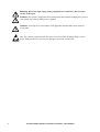
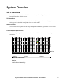
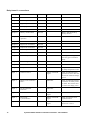
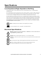
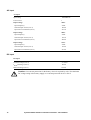
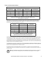
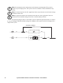
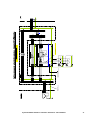
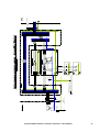
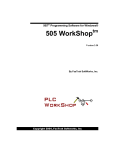
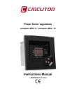
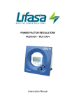
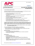
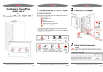
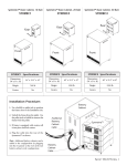
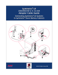
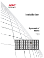
Installation Symmetra MW II ® 1200 kW 400 V X017 X012 X008A X014B X013 X014A X008B X011 X405 X010 X007 X021 X022 Normal Normal UPS Summary ~ ~ Contents Safety ......................................................................1 IMPORTANT SAFETY INSTRUCTIONS - SAVE THESE INSTRUCTIONS . . . . . . . . . . . . . . . . . . . . . . . . . . 1 Symbols used in this guide . . . . . . . . . . . . . . . . . . . . . . . . . 1 Installation safety . . . . . . . . . . . . . . . . . . . . . . . . . . . . . . . 1 System Overview......................................................3 UPS Sections . . . . . . . . . . . . . . . . . . . . . . . . . . . . . . . . . . . . . . . 3 Serial number . . . . . . . . . . . . . . . . . . . . . . . . . . . . . . . . . . 3 Inverter Section . . . . . . . . . . . . . . . . . . . . . . . . . . . . . . . . . 3 Control/Input/Output Section . . . . . . . . . . . . . . . . . . . . . . . 3 External Bypass Static Switch. . . . . . . . . . . . . . . . . . . . . . . . . . . 4 Serial number . . . . . . . . . . . . . . . . . . . . . . . . . . . . . . . . . . 4 Electrical Installation ................................................5 Typical UPS Wiring Principle . . . . . . . . . . . . . . . . . . . . . . . . . . . 5 Power wiring overview . . . . . . . . . . . . . . . . . . . . . . . . . . . . 5 External disconnection switches . . . . . . . . . . . . . . . . . . . . . 6 Input/Output wiring precautions . . . . . . . . . . . . . . . . . . . . . 6 AC and PE cable connections . . . . . . . . . . . . . . . . . . . . . . . 7 Battery cables connection . . . . . . . . . . . . . . . . . . . . . . . . . . 8 External Bypass Static Switch Wiring . . . . . . . . . . . . . . . . . . . . 10 Top cable entry . . . . . . . . . . . . . . . . . . . . . . . . . . . . . . . . 11 Communication cable overview . . . . . . . . . . . . . . . . . . . . . . . . 12 Relay Boards . . . . . . . . . . . . . . . . . . . . . . . . . . . . . . . . . . . . . . 13 Location of relay boards . . . . . . . . . . . . . . . . . . . . . . . . . . 13 Communication cables with optional Relay Board . . . . . . . . . 13 Relay board 1 connections . . . . . . . . . . . . . . . . . . . . . . . . 14 Relay board 2 connections . . . . . . . . . . . . . . . . . . . . . . . . 15 Symmetra MW II 1200 kW 3 x 400/230 V Installation - 990-1979E-001 i Specifications ........................................................ 17 Low-Impedance/High-Impedance Earthing . . . . . . . . . . . . . . . . 17 Electrical Specifications . . . . . . . . . . . . . . . . . . . . . . . . . . . . . . 17 AC Input . . . . . . . . . . . . . . . . . . . . . . . . . . . . . . . . . . . . 18 DC Input . . . . . . . . . . . . . . . . . . . . . . . . . . . . . . . . . . . . 18 AC Output . . . . . . . . . . . . . . . . . . . . . . . . . . . . . . . . . . . 19 AC Input External Bypass SSW . . . . . . . . . . . . . . . . . . . . . 19 Heat dissipation . . . . . . . . . . . . . . . . . . . . . . . . . . . . . . . 19 Notes . . . . . . . . . . . . . . . . . . . . . . . . . . . . . . . . . . . . . . 19 Torque specifications . . . . . . . . . . . . . . . . . . . . . . . . . . . . 20 Required Breaker Settings (400 V Systems) . . . . . . . . . . . . . . . 20 Input and upstream breakers . . . . . . . . . . . . . . . . . . . . . . 20 Output and downstream breakers . . . . . . . . . . . . . . . . . . . 21 Appendix .............................................................. 23 System and Protective Earthing . . . . . . . . . . . . . . . . . . . . . . . . 23 TN Systems . . . . . . . . . . . . . . . . . . . . . . . . . . . . . . . . . . . . . . . 23 Characteristics . . . . . . . . . . . . . . . . . . . . . . . . . . . . . . . . 23 Reference to IEC 60364-4-41 413.1.3 . . . . . . . . . . . . . . . . . 23 Reference to IEC 60364-5-54 546.2.3 . . . . . . . . . . . . . . . . . 23 Additional requirements for generating sets (IEC 60364-5-55 551.4.2) . . . . . . . . . . . . . . . . . . . . . . . . . 24 Protective devices in TN systems . . . . . . . . . . . . . . . . . . . . 24 TT Systems. . . . . . . . . . . . . . . . . . . . . . . . . . . . . . . . . . . . . . . . 25 Characteristics . . . . . . . . . . . . . . . . . . . . . . . . . . . . . . . . 25 Reference to IEC 60364-4-41 413.1.4 . . . . . . . . . . . . . . . . . 25 Protective devices in TT systems . . . . . . . . . . . . . . . . . . . . 25 IT Systems . . . . . . . . . . . . . . . . . . . . . . . . . . . . . . . . . . . . . . . . 26 Characteristics . . . . . . . . . . . . . . . . . . . . . . . . . . . . . . . . 26 Reference to IEC 60364-4-41 413.1.5 . . . . . . . . . . . . . . . . . 26 Protective devices in IT systems . . . . . . . . . . . . . . . . . . . . . 27 ii Symmetra MW II 1200 kW 3 x 400/230 V Installation - 990-1979E-001 Safety IMPORTANT SAFETY INSTRUCTIONS - SAVE THESE INSTRUCTIONS This guide contains important instructions for SYMF1200KH that should be followed when handling the UPS, External Bypass Static Switch, Battery Enclosures, and Batteries. Symbols used in this guide Warning: Indicates an electrical hazard, which, if not avoided, could result in injury or death. Caution: Indicates a hazard, which, if not avoided, could result in injury or death. Note: Indicates important information. Indicates that more information is available on the subject. Main Protective Earthing Terminal symbol. Ground symbol. Installation safety EPO Press the optional EPO (Emergency Power Off) button to switch off all AC and DC power supply to connected equipment in the room and to cut off the load supply. The EPO is typically located on a wall in the room in which the UPS is installed. See “Communication cable overview” section for information on how to wire the UPS to the EPO. Warning: Before you start the installation, verify that all AC and DC power source breakers are in the open position. Warning: Only personnel trained in the construction and operation of the equipment, and the electrical and mechanical hazards involved, must install or remove system components. Symmetra MW II 1200 kW 3 x 400/230 V Installation - 990-1979E-001 1 Warning: Do not use high voltage testing equipment as it will destroy the electronic circuits in the units. Caution: The system is equipped with an optional auto-start function enabling the system to start without any warning when power is applied. Caution: All wiring to be in accordance with applicable national and/or local electrical wiring rules. This unit contains components that are sensitive to electrostatic discharge (ESD). Follow proper ESD procedures to avoid severe damage to electronic components. 2 Symmetra MW II 1200 kW 3 x 400/230 V Installation - 990-1979E-001 System Overview UPS Sections The UPS system consists of two 600 kW Inverter Sections, a Control/Input/Output Section and an External Bypass Static Switch Section. Serial number The serial number is stated on the type label behind the finishing panel above the display unit. Remove finishing panel as described in “Appendix C” to see serial number. Inverter Section The Inverter Sections regulate the UPS output and operates from battery power in the event of mains input loss. Control/Input/Output Section The Control/Input/Output Section controls and monitors the UPS and contains the input/output terminations. X017 X012 X008A X014B X013 X014A X008B X011 X405 X010 X007 X021 X022 Normal Normal UPS Summary ~ 2032 mm ~ 1067 mm Inverter Section Width: 1268 mm Control/Input/Output Section Width: 2110 mm Inverter Section Width: 1268 mm Total width of UPS sections: 4646 mm Weight: Without Power Modules: 5301kg With Power Modules: 6324 kg Symmetra MW II 1200 kW 3 x 400/230 V Installation - 990-1979E-001 3 External Bypass Static Switch The External Bypass Static Switch (External Bypass SSW) transfers the load (manually or automatically) from the UPS to an alternate source without interrupting the supply to the load. Normal ~ 2032 mm ~ 1067 mm 2 MW External Bypass Static Switch Width: 1014 mm Weight: 636 kg Serial number The serial number is stated on the type label behind the finishing panel above the display unit. Remove finishing panel to see serial number. 4 Symmetra MW II 1200 kW 3 x 400/230 V Installation - 990-1979E-001 MAINS 9. Symmetra MW II 1200 kW 3 x 400/230 V Installation - 990-1979E-001 13. 14. 6. UPS AND STATIC BYPASS WITHSTAND RATING, Icw = 200 KA 7. SEE THE INSTALLATION GUIDE FOR THE BREAKER SETTINGS OF Q1, Q3, Q4 AND Q5. 11. 12. 4. ALL AC POWER CABLING IS L1,L2,L3,N,PE. 5. UPS INPUT AND OUTPUT CONDUCTORS MUST BE IN SEPARATE CABLE RUNS. WITH 24VOLT DC UNDER VOLTAGE RELEASE (UVR) AND 2NO/2NC AUXILIARY CONTACTS. 3. Q7, Q8 DC RATED THERMAL MAGNETIC TRIP MOLDED CASE CIRCUIT BREAKER. 10. 8. - Q6 WITH 2NO/2NC AUXILIARY CONTACTS. 2. Q1 6 6 Battery Breaker Box 2 Battery Breaker Box 1 Batteries 2 Batteries 1 INSTALLATION MUST COMPLY WITH NATIONAL AND LOCAL ELECTRICAL RULES. = CABLING PROVIDED BY OTHERS DC CIRCUIT CABLE LENGTHS SHOULD BE EQUAL ON ALL MODULES AC CIRCUIT CABLE LENGTHS (INPUT AND OUTPUT) SHOULD BE EQUAL ON ALL MODULES POWER WIRING AND CONTROL WIRING MUST BE SEGREGATED. SEE BATTERY INSTALLATION INFORMATION DC CABLING SHOULD BE SEGREGATED FROM AC CABLING External Bypass Static Switch Symmetra MW 1. MAINS SOURCE 3X400/230V TN-S (PROVIDED BY OTHERS). Maintenance Bypass Panel (MBP) 9 9 Electrical Installation Typical UPS Wiring Principle Power wiring overview See separate guide on parallel operation for wiring overview in parallel systems. 5 External disconnection switches Warning: The UPS has no built-in disconnect devices to switch off external AC (Q1 and Q5) and DC (Q7 and Q8) input power. Ensure that the disconnect devices are available as separate components for this installation. Note: The installer must provide each external disconnect device for this UPS system with labels displaying the following text: “Isolate the Uninterruptible Power Supply (UPS) as instructed in the User Guide before working on the circuit.” Input/Output wiring precautions Warning: Only personnel trained in the construction and operation of the equipment, and the electrical and mechanical hazards involved, must install or remove system components. Warning: Before you start the installation, verify that all AC and DC power source breakers are in the open position. Warning: Supply the UPS from a 3 × 400/230 V, L1, L2, L3, N, PE source or a highimpedance grounded system. Caution: All wiring to be in accordance with applicable national and/or local electrical wiring rules. Note: Use only copper conductors. 6 Symmetra MW II 1200 kW 3 x 400/230 V Installation - 990-1979E-001 AC and PE cable connections Top view of top cover For battery grommets For AC and PE grommets For AC and PE grommets N Normal UPS Summary ~ ~ L1 IN L2 IN L3 IN L1 OUT L2 OUT L3 OUT Note: No drilling or cutting should take place over the top of the UPS. Symmetra MW II 1200 kW 3 x 400/230 V Installation - 990-1979E-001 7 1. With the top covers removed, drill holes for AC, PE and Battery grommets in areas shown. 2. Re-fit the covers and install the grommets. 3. Feed AC and PE cables through grommets in the Control/Input/Output Section. Hole distance DC Busbar 44.45 mm 44.45 mm 35.8 mm Hole distance grounding Hole distance AC Cable lug fl 13 Cable lug Busbar 44.45 mm 44.45 mm 58 mm Cable lug Busbar 44.45 mm 44.45 mm fl 13 46.99 mm M10 stud 4. Connect PE cable. 5. Connect AC IN cables to normal power and bypass power. 6. Connect AC OUT cables. Battery cables connection Warning: Make sure that the battery breakers are open (OFF) prior to running the cables. Caution: For battery installation and maintenance instructions, refer to the battery manufacturer’s installation manual. Caution: Over-current protection for the battery circuit is required by code. The minimum DC voltage rating of the battery supply over-current protection device is 500 V. Note: Over-current protection for the battery circuit is required by national wiring rules. 8 Symmetra MW II 1200 kW 3 x 400/230 V Installation - 990-1979E-001 X017 X012 X008A X014B X013 X014A X008B X011 X405 X010 Normal Normal X007 X021 UPS Summary X022 ~ BAT1 + BAT1 - BAT2 - ~ BAT2 + 1. Feed the battery cables through the grommets. 2. Connect battery cables to Bat 1+ and Bat 1-. 3. Connect battery cables to Bat 2+ and Bat 2-. Note:The battery cables can be connected on either side of the busbar. Symmetra MW II 1200 kW 3 x 400/230 V Installation - 990-1979E-001 9 External Bypass Static Switch Wiring Warning: Before you start the installation, verify that all AC and DC power source breakers are in the open position. Warning: Use only manual reset protection as input over-current protection. Warning: Over-current protection required by national wiring rules. Warning: The UPS has no built-in disconnect devices to switch off external AC (Q1 and Q5) and DC (Q7 and Q8) input power. Ensure that the disconnect devices are available as separate components for this installation. Caution: The External Bypass Static is not provided with built-in backfeed protection. Use suitable breakers with a minimum of 0.8 in/20 mm air gap and trip function. The breaker is controlled from the External Bypass SSW and will be tripped in case of backfeed. Note: The installer must provide each external disconnect device for this UPS system with labels displaying the following text: “Isolate the Uninterruptible Power Supply (UPS) as instructed in the User Guide before working on the circuit.” Note: The installation of the External Bypass Static Switch must comply with local and national regulations. Note: Run matched set of phase cables in the same cable run(s). Do not separate phases into different cable runs. Note: Use only copper conductors. 10 Symmetra MW II 1200 kW 3 x 400/230 V Installation - 990-1979E-001 Top cable entry Top view of top cover X017 X012 X008A X014B X013 X014A X008B X011 X405 X010 Normal Normal X007 X021 UPS Summary X022 ~ Top view of input and output L3 OUT L3 IN L2 OUT L2 IN L1 OUT L1 IN ~ L1 IN L1 OUT L2 IN L3 IN L2 OUT L3 OUT Side view of PE busbar. 1. Loosen the 8 bolts to remove top cover. Note: No drilling or cutting should take place over the top of the UPS. 2. Drill holes for grommets. 3. Re-fit the covers and install the grommets. 4. Feed the cables through the grommets. Connect cables at cable connection points. 5. Connect Protective Earth conductor to busbar locations. Symmetra MW II 1200 kW 3 x 400/230 V Installation - 990-1979E-001 11 Communication cable overview Terminator 0N-0765 External Bypass Static Switch Maintenance Bypass Panel Relay output X134A 1 1 2 + C1 + Note 3 4 2 3 2 1 1 Q 1 2 2 1 3 + 4 5 6 - + - + H3 Lamps X172 8 9 10 11 7 H4 - + H5 1 12 + - H6 X176 3 4 2 - + 5 - 6 + Q5 - Q6 24VDC Shunt trip for back feed protection + External Lamp supply VDC or VDC - Max. 250VAC 5A Terminator 0N-0765 UPS 2 6 7 8 X172 Lamps 9 11 10 12 Note 1 C2 + C1 1 6 5 X173 MBP Breakers X176 3 4 - 2 + Q1 - 1 EMO (Display) - + 1 2 24VDC Shunt trip Relay output Maintenance Bypass Panel H8 H7 Note 2 Q8 4 1 2 3 X183 Fuse3 Fuse1 X186 1 2 3 4 5 6 7 8 Fuse2 X133A Note 1: Contact APC Application Team for correct sizing. Note 2: H7, H8 = 2V LED Note 3: Q2, Q4 and Q6 are optional. If Q2 is not present pins 3 and 4 must be shorted on both boards. If Q4 is not present pins 7 and 8 must be shorted on both boards. If Q6 is not present pins 11 and 12 must be shorted on both boards. Symmetra MW II 1200 kW 3 x 400/230 V Installation - 990-1979E-001 UVR + - UVR + 4 Battery CAN I/O board ID 0 X185 0P4512 X133B 4 3 - X184 2 3 X182 - 1 2 12 34 X180 1 2 + X181 1 2 3 4 Q7 1 - Fuse4 Backfeed protection Earth fault sensor X174 1 X127A Norm.op X175 2 1 2 EPO out X185 1 2 1 Note 3 X129 1 2 1 2 X128 9 10 11 12 X129 2 + + 8 X128 MBP CAN I/O board1 0P4533 + 12 - 12 3 4 X170 7 X130 6 X127B 1 External EPO 2 placed on wall 4 5 X126B 5 X177 2 3 X126A 4 1 X131 X133A 3 3 1 2 2 2 1 1 X178 Connection plane 0P0957 EPO out X177 X134A 4 X134B X134A Q2 X127A 3 0P4533 Q 2 X126A 1 4 6 5 X127B 7 Q 3 X129 C2 MBP CAN I/O board 2 8 Q 4 X126B Note 1 - 1 EMO (Display) Q 5 X128 X174 Earth fault sensor X129 12 11 10 9 Q 6 X131 12 3 4 X170 X175 Norm.op X128 2 1 2 X130 X134B X177 X178 2 2 1 2 1 1 2 X177 MBP Breakers X173 Connection plane 0P0957 X134A Q8 Q7 Temp sensor NTC + Temp sensor NTC + Relay Boards Location of relay boards Normal UPS Summary ~ ~ Relay boards Communication cables with optional Relay Board Backplane X008A Fan CAN X008A Symmetra MW II 1200 kW 3 x 400/230 V Installation - 990-1979E-001 13 Relay board 1 connections 14 Relay Function Mode Special Comments Output 1 Common alarm Fail safe Output 2 Normal operation Active on Output 3 Bypass operation Active on Output 4 Battery operation Active on Output 5 VDC out of tolerance Fail safe Output 6 Battery conditon fault Fail safe Output 7 Maintenance bypass operation Active on Output 8 Mains out of tolerance Fail safe Output 9 Bypass out of tolerance Fail safe Output 10 Output out of tolerance Fail safe Output 11 MCCB open Fail safe Output 12 System overload Fail safe Output 13 Good utility Active on Output 14 Boost charge active Fail safe Output 15 Fan fault Fail safe Output 16 Temperature fault Fail safe Input 1 Generator active Master will handle signal Input for indicating that a generator is active. This will be used to reduce the charge power Input 2 Battery room ventilation fault Individual Input for indicating that the ventilation in battery rooms is defect. This will be used to reduce the charge power Input 3 DC Ground Fault Detection Individual Input 4 Reserved for future use Master will handle signal Input 5 Plant clock synchronization Master will handle signal Input for real time clock synchronization Input 6 Power Tie detection Master will handle signal Input from PLC to detect if Power Tie is active Battery fault detected by battery monitor Battery breakers open If UPS goes into bypass, this relay goes on without delay Temperature switch active or faulty temperature sensor Symmetra MW II 1200 kW 3 x 400/230 V Installation - 990-1979E-001 Relay Function Input 7 Reserved for future use Input 8 Reserved for future use Mode Special Comments Special Comments Relay board 2 connections Relay Function Mode Output 1 Info level alarm Fail safe Output 2 Warning level alarm Fail safe Output 3 Severe level alarm Fail safe Output 4 Input frequency too high Fail safe Output 5 Input frequency too low Fail safe Output 6 Output frequency too high Fail safe Output 7 Output frequency too low Fail safe Output 8 Bypass source fault Fail safe Output 9 Close Q7 pulse Active on No delay Output 10 Close Q8 pulse Active on No delay Output 11 Power Tie mode active Active on No delay Output 12 Close Q2 Fail safe No delay Output 13 Reserved for future use Output 14 Reserved for future use Output 15 Reserved for future use Output 16 Reserved for future use Input 1 Reserved for future use Input 2 Reserved for future use Input 3 Reserved for future use Input 4 Reserved for future use Input 5 Reserved for future use Input 6 Reserved for future use Input 7 Reserved for future use Input 8 Reserved for future use Symmetra MW II 1200 kW 3 x 400/230 V Installation - 990-1979E-001 15 16 Symmetra MW II 1200 kW 3 x 400/230 V Installation - 990-1979E-001 Specifications Low-Impedance/High-Impedance Earthing The Symmetra® MW is easily integrated into either a solid grounded system, or a high-impedance grounded system. In a solid grounded system, the neutral power source (mains, generator, or UPS) is solidly grounded. In the event of a down-stream ground fault, the fault current will have a path back to the source, and the over-current device feeding the faulted part of the installation will trip and isolate the fault. In a high-impedance grounded system, the source is grounded with an impedance (grounding resistor). In the event of a down-stream fault, the fault current will be limited by the impedance of the grounding resistor. The value of a high-impedance system is its ability to maintain operation with a given system fault to ground, i.e. the over-current device will only trip at line-to-line faults or double ground faults. For a high-impedance system to provide enhanced power system reliability and availability, a groundfault monitoring/alarm system is required. Note: Grounding electrode conductor to be supplied by the customer. For more information refer to “Appendix” in Installation Guide. Electrical Specifications Warning: Supply the UPS from a dedicated, 3 × 400/230 V, L1, L2, L3, N, PE source or a high-impedance grounded system. Caution: Ensure clockwise phase rotation (L1, L2, L3) of input voltages. Caution: AC and DC disconnect switches and overcurent protection must be included in the installation. Note: All wiring must comply with all applicable national and/or local electrical codes. Note: Max. prospective RMS short-circuit current on input terminals: 200 kA Max. prospective RMS short-circuit current on DC terminals: 50 kA Symmetra MW II 1200 kW 3 x 400/230 V Installation - 990-1979E-001 17 AC Input AC Input Input rating 1200 kW/kVA Power Factor 1 Input Voltage 380 V Input Frequency 50 Hz Nominal input current (note 1) 1698 A Input Current Limitation (note 2) 2133 A Input Voltage 400 V Input Frequency 50 Hz Nominal input current (note 1) 1793 A Input Current Limitation (note 2) 2200 A Input Voltage 415 V Input Frequency 50 Hz Nominal input current (note 1) 1728 A Input Current Limitation (note 2) 2170 A DC Input DC Input Nominal Voltage (note 3) 2 x 384 V INom Discharge (note 4) 1628 A IMax Discharge (note 5) 1929 A Caution: Over-current protection for the battery circuit is required by code. The minimum DC voltage rating of the battery supply over-current protection device is 500 V. 18 Symmetra MW II 1200 kW 3 x 400/230 V Installation - 990-1979E-001 AC Output AC Output Voltage 380 V Current Nom (note 8) 1641 A Max (note 7) 2051 A Voltage 400 V Current Nom 1732 A Max (note 7) 2165 A Voltage 415 V Current Nom 1669 A Max (note 7) 2087 A AC Input External Bypass SSW The External Bypass SSW is designed to accommodate a continuous overload of 25%. AC Input External Bypass SSW External Bypass SSW Max Input Current (100% load) 380 V 1641 A 400 V 1732 A 415 V 1669 A Heat dissipation 37.1 kW / 126.7 kBTU/hr (note 6). Notes 1. Nominal (Nom): Input current based on rated load, nominal input voltage and fully charged batteries. 2. Current limitation is maximum allowed via electronic current limiting and is based on full battery recharge + nominal load and -10% input voltage. 3. Nominal battery voltage assumed to be 2.0 volts/cell (lead technology). 4. Nominal Battery Discharge current based on rated load, and nominal Battery voltage. 5. Maximum Battery Discharge current based on rated load at end of Discharge. 6. Heat dissipation calculated at rated load capacity. 7. This current is at 125% of rated load and is electronically current-limited to a maximum of 10 minutes. This value is only provided so the engineer can ensure that the selected AC output circuit overcurrent device’s time-current characteristic will support this condition. 8. At 380 V, nominal output is reduced from 200 kW to 180 kW in each section. Symmetra MW II 1200 kW 3 x 400/230 V Installation - 990-1979E-001 19 Torque specifications Torque specifications Bolt Size M8 13.5 Nm Bolt Size M10 30 Nm Bolt Size M12 50 Nm Bolt Size M14 75 Nm Required Breaker Settings (400 V Systems) Note: Contact APC Application Team for Required Breaker Settings in 380 V and 415 V systems. The Symmetra® MW is a fault-tolerant system capable of handling and surviving overloads and internal/external faults. The overload performances and fault clearings are possible when the system meets specified minimum requirements for breaker settings. A proper breaker coordination study is required to ensure the highest availability of the UPS. This breaker coordination study should be performed focusing on maintaining the fault tolerant characteristics of the Symmetra MW. The following tables provide the optimum settings for the input and output breakers. The settings are specified in the tables below, but some of them can also be found in the Electrical Specification section. See separate manual on parallel operation for information on required breaker settings in parallel systems. Input and upstream breakers Q1, Q5, and any upstream breaker Duration [S] Current [A] Total load [%] Event/Operation < 0.005 22 kA -- Internal fault clearing ∞ 2200* 127 Overload on-line ∞ 1793 100 On-line ∞ 1972 110 On-line+ Max. Battery charge * In the absence if a coordination study conducted by a professional engineer, the recommended instantaneous trip setting for breakers Q1, Q2, Q4, Q5, and Q6 is 22 kA ** Only applicable to Q1 20 Symmetra MW II 1200 kW 3 x 400/230 V Installation - 990-1979E-001 Output and downstream breakers Q2, Q4, Q6 Duration [S] Current [A] Total load [%] Event/Operation < 0.005 22 kA -- Internal fault clearing. 60 3464* 200 Overload on-line 600 2165* 125 Overload on-line ∞ 1732 100 On-line * In the absence if a coordination study conducted by a professional engineer, the recommended instantaneous trip setting for breakers Q1, Q2, Q4, Q5, and Q6 is 22 kA ** Only applicable to Q2 and Q4 In the absence of a proper breaker coordination study and if only the actual Ip on the unit’s input terminals is known, this table must be used to optimize the instantaneous trip setting or to choose a breaker with a usable fixed instantaneous trip value. Ip* [kA] I peak let-through [kA] I setting [kA] 200 16 18 140 14 16 100 13 15 50 10.5 12 30 9 11 * Ip = Abridgment for Prospective short-circuit current. This is the current that would flow in the fault circuit is the fuse was replaced by a link with an infinitely small impedance 22 kA is the maximum peak let-through current (including safety factor) present during clearing of an internal fault in a 200 kW section or a power module. This maximum peak let-through current is based on and applicable to utility with prospective short-circuit currents (Ip) up to 200 kA.During or after a controlled fault clearing, none of the breakers are allowed to trip on the instantaneous trip setting below the specified value. This is also applicable to the upstream breakers, and a check of the instantaneous trip setting in this part of the installation is required. The instantaneous trip setting calculated by a professional engineer in a breaker coordination study must not disable the functionality of clearing and surviving an internal fault unless there is a written agreement between APC by Schneider Electric and the customer. By ensuring the unit’s fault clearing ability (survival skills) i.e. using the correct instantaneous trip settings in the switch gear (installation), maximum power availability in normal operation is obtained for the critical load. Note: The instantaneous trip setting can be calculated when utility Ip is known. An incorrect trip setting can result in limiting the system functionality and jeopardize the load support. Symmetra MW II 1200 kW 3 x 400/230 V Installation - 990-1979E-001 21 Note: The instantaneous trip setting must not be derated even though the UPS system is derated in system output power. The system size has no influence on the instantaneous trip setting. Note: For derated systems, the APC Application Team can provide the correct breaker settings and breaker frame sizes. Note: For upstream breakers not mentioned in the table, the APC Application Team can provide the correct breaker settings for on-line, overload, and trip currents. The following diagram shows a dual mains system in which the upstream breakers are named Q. Correct settings of upstream breaker settings are mandatory. The system can also be configured as a single mains system. Dual Mains Installation Q3 T1 Q Q5 Q6 Q Q1 Q2 T2 22 Symmetra MW II 1200 kW 3 x 400/230 V Installation - 990-1979E-001 Q4 Appendix System and Protective Earthing The purpose of this appendix is to describe the system- and protective earthing principles of the Symmetra® MW. Caution: All wiring to be in accordance with applicable national and/or local electrical wiring rules. TN Systems Characteristics TN systems have one point connected directly to ground. All exposed conductive parts must be connected to that point by protective conductors. Depending on the way the neutral and protective conductors are fed, there are three types of TN systems: • TN-S system: a separate protective conductor is used in the system • TN-C-S system: the neutral and protective conductors are combined to one single conductor in a part of the system • TN-C system: the neutral and protective conductors are combined to one single conductor in the whole system Reference to IEC 60364-4-41 413.1.3 All exposed conductive parts of the installation must be connected to the earthed point of the power system by protective conductors which must be earthed at or near to each relevant transformer or generator. Exposed conductive parts that are accessible at the same time must be connected to the same earthing system, either individually, in groups or collectively. Normally the earthed point of the power system is the neutral point. If a neutral point is not available or accessible, a phase conductor must be earthed. The phase conductor must not serve as a PEN conductor. In fixed installations a single conductor may serve both as a protective conductor and a neutral conductor (PEN conductor). Reference to IEC 60364-5-54 546.2.3 If from any point in the installation the neutral and protective functions are provided by separate conductors, it is inadmissible to connect these conductors to each other from that point. At the point of separation, separate terminals or bars must be provided for the protective and neutral conductors. The PEN conductor must be connected to the terminal or bar intended for the protective conductor. Symmetra MW II 1200 kW 3 × 400/230 V Installation - 990-1979E-001 23 If there are other effective earth connections, the protective conductors must be connected to such points when it is possible. It may be necessary to earth at additional points to ensure that the potentials of protective conductors remain as close as possible to that of earth in case of a fault. Additional requirements for generating sets (IEC 60364-5-55 551.4.2) To be used when the generating set provides a switched alternative to the public supply. Protection by automatic disconnection of supply must not rely on the connection to the earthed points of the public supply system when the generator is operating as a switched alternative to a TN system. A suitable earth electrode must be provided. Protective devices in TN systems The following protective devices are recognized in TN systems: • Overcurrent protective devices • Residual current protective devices (not to be used in TN-C systems) SOURCE L1 L1 Residual Current Sense When a residual current protective device is used in a TN-C-S system, a PEN conductor must not be used on the load side. The connection of the protective conductor to the PEN conductor must be made on the source side of the residual current protective device (see below illustration): L1 PEN L1 L1 L1 N LOAD PE The characteristics of protective devices and the circuit impedances shall be such that, if a fault of negligible impedance occurs anywhere in the installation between a phase conductor and a protective conductor or exposed conductive part, automatic disconnection of the supply will occur within 5 seconds (valid for distribution circuits), the following condition fulfilling this requirement: Zs × I a ≤ U0 In the condition: 24 Zs is the impedance of the fault loop comprising the source, the live conductor up to the point of the fault, and the protective conductor between the point of the fault and the source Ia is the current causing the automatic operation of the disconnecting protective device within a conventional time not exceeding five seconds U0 is the nominal AC RMS voltage to earth Symmetra MW II 1200 kW 3 × 400/230 V Installation - 990-1979E-001 If a fault occurs close to the UPS (before the power distribution) while the UPS system is in Battery Operation and Bypass is unavailable, the available power is unable to activate the protective device. In that situation the Inverter will shut down in five seconds (IEC 60364-4-41 413.1.3.5 norm). If a residual current protective device is used, this device will disconnect the supply. The four diagrams show the Symmetra MW installed in four different TN systems: • Earthing arrangements and protective conductors - Symmetra® MW in “TN-S installation” • Earthing arrangements and protective conductors - Symmetra® MW in “TN-S installation” (Legal in DK - special cases) • Earthing arrangements and protective conductors - Symmetra® MW in “TN-C-S installation” • Earthing arrangements and protective conductors - Symmetra® MW in “TN-C installation” TT Systems Characteristics TT systems have one point connected directly to ground and all exposed conductive parts of the installation must be connected to an earth electrode. This earth electrode is independent of the power system earthed point. Reference to IEC 60364-4-41 413.1.4 All exposed conductive parts that are protected collectively by the same protective device must be connected to a common earth electrode together with the protective conductors. In installations where several protective devices are utilized in series, the requirement applies separately to all exposed conductive parts protected by each device. The neutral point or, if a neutral point does not exist, a phase conductor of each generator station or transformer station must be earthed. Protective devices in TT systems The following protective devices are recognized in TT systems: • Overcurrent protective devices • Residual current protective devices Overcurrent protective devices are only applicable for protection against indirect contact in TT systems where a low RA value exists (see specification below). The condition R A × I a ≤ 50V must be fulfilled. In the condition: RA is the sum of resistance of the earth electrode and the protective conductor for the exposed conductive parts Ia is the current causing the automatic operation of the protective device. When the protective device is a residual current protective device, Ia is the rated residual operating current I Δ n Symmetra MW II 1200 kW 3 × 400/230 V Installation - 990-1979E-001 25 For discrimination purposes, S-type residual current protective devices may be used in series with general type residual current protective devices. To provide discrimination with S-type residual current protective devices, an operating time not exceeding 1 second is permitted in distribution circuits. When the protective device is an overcurrent protective device, it must be either: • a device with inverse time characteristics and Ia must be the current causing automatic operation within 5 seconds, or • a device with an instantaneous tripping characteristic and Ia must be the minimum current causing instantaneous tripping The following diagram shows a Symmetra® MW installed in a TT system: • Earthing arrangements and protective conductors - Symmetra® MW in “TT installation” IT Systems Characteristics In IT systems the installation is insulated from earth or connected to earth through a sufficiently high impedance. Exposed conductive parts are earthed individually, in groups, or collectively. Reference to IEC 60364-4-41 413.1.5 In IT systems the installation must be insulated from earth or connected to earth through a sufficiently high impedance. This connection must be made either at the neutral point of the system or at an artificial neutral point. The latter may be connected directly to earth if the resulting zero-sequence impedance is sufficiently high. In installations where no neutral point exists, a phase conductor can be connected to earth through an impedance. In case of a single fault to an exposed conductive part or to earth, the fault current will be low and disconnection will not be imperative. Exposed conductive parts must be earthed individually, in groups or collectively and the condition RA × Id ≤ 50V must be fulfilled. In the condition: RA is the resistance of the earth electrode for exposed conductive parts Id is the fault current of the first fault of negligible impedance between a phase conductor and an exposed conductive part. The Id value takes the leakage currents and the total earthing impedance of the electrical installation into account In systems where an IT system is used for continuity of supply, an insulation monitoring device must be provided to indicate the occurrence of a first fault from a live part to the exposed conductive parts or to the earth. It is recommended to eliminate a first fault as soon as possible. 26 Symmetra MW II 1200 kW 3 × 400/230 V Installation - 990-1979E-001 Depending on whether all exposed conductive parts are interconnected by a protective conductor (collectively earthed) or are earthed in groups or individually, after a first fault, the disconnection conditions of the supply for a second fault must be as follows: 1. In installations where the exposed conductive parts are earthed in groups or individually, the protection conditions for TT systems apply (see 413.1.4.1) 2. In installations where the exposed conductive parts interconnected by a protective conductor collectively earthed, the conditions for TN systems apply In installations where the neutral is not distributed, the following conditions must be fulfilled: 3 × U0 Z s ≡ -------------------2 × Ia In installations where the neutral is distributed, the following conditions must be fulfilled: U0 Z′ s ≤ ------------2 × Ia In the condition: U0 is the nominal AC RMS voltage between phase and neutral Zs is the impedance of the fault loop comprising the phase conductor and the protective conductor of the circuit Z′ s is the impedance of the fault loop comprising the neutral conductor and the protective conductor of the circuit Ia is the operating current of the protective device. The disconnecting time is 5 seconds (distribution circuits) Protective devices in IT systems The following protective devices are recognized in IT systems: • Insulation monitoring devices • Overcurrent protective devices • Residual current protective devices The following diagram shows a Symmetra® MW installed in a IT system: • Earthing arrangements and protective conductors - Symmetra® MW in “IT installation” Symmetra MW II 1200 kW 3 × 400/230 V Installation - 990-1979E-001 27 N PE Residual current protective device can not be used at this point. Owing to parallel return path for the fault current Minimum cross-sectional areas: IEC 364-5-54 § 543.1.1 With reference to: IEC 60364-4-41 § 413.1.3.1 Residual Current Sense Suitable earth electrode with reference to IEC 60364-5-55 § 551.4.2 Protective Earthing Conductor Q1 Q5 Switchgear Symmetra MW II 1200 kW 3 × 400/230 V Installation - 990-1979E-001 PE Battery rack PE Battery breaker box Q7 PE E N L3 L2 L1 Mains - input PE L3 L2 L1 Bypass - input - Battery 2 - Q8 i Delta Inverter Battery 2 + i i M Main inverter u Main Protective Earthing Terminal u Symmetra MW Main Protective Earthing Terminal External SSW-Bypass Q3 See: IEC 60364-4-41 § 413.1.3 Battery 1 + Battery 1 Service Entrance Common-mode filter Protective Earthing Conductor PE N L3 L2 L1 UPS - output PE L3 L2 L1 Bypass - output Q6 Q4 Earthing arrangements and protective conductors - Symmetra MW inSTNinstallation u 28 Residual Current Sense PE Residual current protective device can be used. ( PDU ) Symmetra MW II 1200 kW 3 × 400/230 V Installation - 990-1979E-001 29 N PE Residual current protective device can not be used at this point. Owing to parallel return path for the fault current Minimum cross-sectional areas: IEC 364-5-54 § 543.1.1 With reference to: IEC 60364-4-41 § 413.1.3.1 With reference to: Stærkstrømsbekendtgørelsen § 551.6.3 Note ( § 551.6.3 is missing in IEC 60364-5-55 ) Legal in DK ( Special cases ) Protective Earthing Conductor Q1 Q5 PE Battery rack PE Battery breaker box Q7 PE E N L3 L2 L1 Mains - input PE L3 L2 L1 Bypass - input Battery 1 + Common-mode filter Battery 1 Switchgear - Battery 2 - Q8 i Delta Inverter Battery 2 + i i M Main inverter u Main Protective Earthing Terminal u Symmetra MW Main Protective Earthing Terminal External SSW-Bypass Q3 PE N L3 L2 L1 UPS - output PE L3 L2 L1 Bypass - output See: IEC 60364-4-41 § 413.1.4 and "Stærkstrømsbekendtgørelsen" § 551.6.3, Note u Service Entrance Residual Current Sense Q6 Q4 Earthing arrangements and protective conductors - Symmetra MW in "TNS installation" ( Legal in DK - specialcases ) Residual Current Sense Protective Earthing Conductor PE Residual current protective device can be used. ( PDU ) PEN Service Entrance With reference to: IEC 60364-4-41 § 413.1.3.1 PEN Residual current protective device can not be used. Residual Current Sense PE Suitable earth electrode with reference to IEC 60364-5-55 § 551.4.2 Q1 Q5 Bypass - input Symmetra MW II 1200 kW 3 × 400/230 V Installation - 990-1979E-001 PE Battery rack PE Battery breaker box Q7 PE E N L3 L2 L1 Mains - input PE L3 L2 L1 Battery 1 + Battery 1 Switchgear Common-mode filter Protective Earthing Conductor - Battery 2 - Q8 i Delta Inverter Battery 2 + i i M Main inverter u Main Protective Earthing Terminal u Symmetra MW Main Protective Earthing Terminal External SSW-Bypass Q3 See: IEC 60364-4-41 § 413.1.3 PE N L3 L2 L1 UPS - output PE L3 L2 L1 Bypass - output Q6 Q4 Earthing arrangements and protective conductors - Symmetra MW in "TN-C-S installation" u 30 Residual Current Sense PE Residual current protective device can be used. ( PDU ) Symmetra MW II 1200 kW 3 × 400/230 V Installation - 990-1979E-001 31 PEN With reference to: IEC 60364-4-41 § 413.1.3.1 PEN PEN Suitable earth electrode with reference to IEC 60364-5-55 § 551.4.2 Q1 Q5 PE Battery rack PE Battery breaker box Q7 PE E N L3 L2 L1 Mains - input PE L3 L2 Battery 1 + - Q3 - Q8 i M Main inverter u PE N L3 L2 L1 UPS - output PE L3 L2 L1 Bypass - output The "Common-Mode Filter" has no effect in this system configuration. Main Protective Earthing Terminal u Symmetra MW External SSW-Bypass Delta Inverter Battery 2 + i i Main Protective Earthing Terminal Bypass - input L1 Common-mode filter Battery 1 Switchgear Battery 2 Service Entrance This system configuration is not recommended See: IEC 60364-4-41 § 413.1.3 PEN Q6 Q4 Earthing arrangements and protective conductors - Symmetra MW inCTNinstallation u PEN PE N ( PDU ) N Residual current protective device can not be used at this point. Owing to parallel return path for the fault current With reference to IEC 60364-4-41 § 413.1.4.1 Residual Current Sense PE With reference to IEC 60364-4-41 § 413.1.4.2 Suitable earth electrode: R A x Ia < 50V Q1 Q5 Switchgear Bypass - input Symmetra MW II 1200 kW 3 × 400/230 V Installation - 990-1979E-001 PE Battery rack PE Battery breaker box Q7 PE E N L3 L2 L1 Mains - input PE L3 L2 L1 Battery 1 + - Battery 2 - Q8 i Delta Inverter Battery 2 + i i M Main inverter u Main Protective Earthing Terminal u Symmetra MW Main Protective Earthing Terminal External SSW-Bypass Q3 See: IEC 60364-4-41 § 413.1.4 Common-mode filter Battery 1 Service Entrance Protective Earthing Conductor PE N L3 L2 L1 UPS - output PE L3 L2 L1 Bypass - output Q6 Q4 Earthing arrangements and protective conductors - Symmetra MWTT ininstallation u 32 Residual Current Sense PE Residual current protective device can be used. ( PDU ) Symmetra MW II 1200 kW 3 × 400/230 V Installation - 990-1979E-001 33 N Grounding Z impedance Requirement !! IEC 60664-4-41 § 413.1.5.4 Insulation Monitoring Device Grounding impedance Z Suitable earth electrode: RA x Id < 50V With reference to IEC 60364-4-41 § 413.1.5.3 Alternative: The exposed-conductive-parts can be earthed individually or in groups. But special demands are required. See IEC 60364-4-41 § 413.1.5.5 a) ( Alternative to earth electrode ) Protective Earthing Conductor Q1 PE Battery rack PE Battery breaker box Q7 PE E N L3 L2 L1 Mains - input PE L3 L2 Battery 1 + - Q3 - Q8 i M Main inverter u Main Protective Earthing Terminal u Symmetra MW External SSW-Bypass Delta Inverter Battery 2 + i i Main Protective Earthing Terminal Bypass - input L1 Common-mode filter Battery 1 Q5 Battery 2 Switchgear u Service Entrance Earthing Conductor See: IEC 60364-4-41 § 413.1.5 PE N L3 L2 L1 UPS - output PE L3 L2 L1 Bypass - output Q6 Q4 Earthing arrangements and protective conductors - Symmetra MW in - "IT installation" Residual Current Sense PE Residual current protective device can be used. ( PDU ) APC Worldwide Customer Support Customer support for this or any other APC product is available at no charge in any of the following ways: • Visit the APC Web site to access documents in the APC Knowledge Base and to submit customer support requests. – www.apc.com (Corporate Headquarters) Connect to localized APC Web sites for specific countries, each of which provides customer support information. – www.apc.com/support/ Global support searching APC Knowledge Base and using e-support. • Contact the APC Customer Support Center by telephone or e-mail. – Local, country-specific centers: go to www.apc.com/support/contact for contact information. For information on how to obtain local customer support, contact the APC representative or other distributors from whom you purchased your APC product. Entire contents copyright 2009 American Power Conversion Corporation. All rights reserved. Reproduction in whole or in part without permission is prohibited. APC, the APC logo, and Symmetra are trademarks of American Power Conversion Corporation. All other trademarks, product names, and corporate names are the property of their respective owners and are used for informational purposes only. 990-1979E-001 *990-1979E-001* 4/2009