1
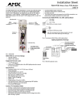
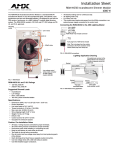
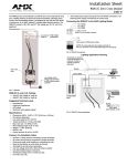
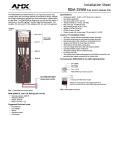
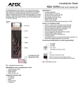
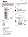
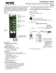
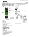
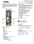
Installation Sheet
RDM-FDB Single Channel Lutron FDB Ballast Dimmer
1920 W
The RDM-FDB Single Channel Ballast Dimmer is a 1920 W positive air gap
relay and dimmer, built for strength and for reliable switching/dimming of
Lutron FDB ballasts. It is designed for use with the RDA series of enclosures, in a AMX Lighting™ modular digital dimming system. The RDM-FDB
module's 120, 240, and 277 VAC ratings are CE, UL, and C-UL approved.
Mounting points
Relay
Connecting the RDM-FDB to the AMX Lighting Master
Pin 4 (GND)
Pin 3 (RLY)
Pin 2 (DIM)
Pin 1 (+12 V)
RDM-FDB 4-pin module connector
Line in (hot)
Switched out Ballast A
Dimmed out
3 (-)
2 (AC)
1 (+)
4-pin plug from RDM series module
Positive air
gap relay
Note: The 4-pin plugs from the module connector
to the 4-pin connector on the master (black plug cover facing up).
Fuse
FIG. 2 RDM-FDB connections
Lighting Appplication Drawing
All neutrals are
common to the
Neutral block in the
enclosure. Provide
a separate neutral
for each load.
Neutral
Neutral
Line in (HOT)
Florescent
Ballast
Ballast
BALLAST
Low-voltage
control wiring: 4-pin
connector to AMX
Lighting master
controller
Switched
Dimmed
Circuit breaker
panel
FIG. 1 RDM-FDB
RDM-FDB UL and C-UL Ratings
•
•
120 VAC, 1920 W
240/277 VAC, 1920 W
Suggested Dimmed Loads
•
Most 3-wire dimmable fluorescent ballasts
•
Lutron© Hi-Lume® FDB Ballasts
•
Lutron Eco-10® Ballasts
Specifications:
•
•
•
•
•
•
•
•
•
•
•
Dimensions (HW): 10.0" x 2.75" (25.4 cm x 6.99 cm)
Dimmed output protected by a 250 mA GMA 5 x 20 mm fuse
Phase dependant
Use wires rated at 75°C (167°F)
Torque terminals to 20 in-lbs. (2.3 N/M)
Max. wire size: 10 AWG (4 mm²)
Wire stripping length: 0.28" (7 mm)
Weight: .72 lbs. (0.327 kg)
BTU/hr: 5
Control current: 85 mA @ 12 VDC
For use with FDB ballasts
Caution: Pre-Installation Notes
•
•
•
•
•
•
•
•
All Class 1 wiring must be connected to proper terminals.
All control wiring must be connected to proper terminals.
Disconnect power while installing or connecting the unit.
Keep top and bottom air vents clear at all times.
Use field installed copper conductors.
All electrical ratings are for continuous duty.
For indoor use only.
This module may require extra power from the AXlink connection or an
external power supply connected to the control card.
FIG. 3 RDM-FDB wiring configuration
The fuse protects the dimming
circuit from a low impedance
load.
• The fuse would blow if it
were incorrectly wired
• Catastrophic ballast failure
• Reversing switched and
dimmed circuits
• Reversing dimmed and
line circuits.
The dimmed output must be
connected to a high impedance
load.
AMX Corporation reserves the right to alter specifications without notice at any time.
For full warranty information, refer to the AMX Instruction Manual(s) associated with your Product(s).
043-019-2483 8/01 ©2001 AMX Corporation. All rights reserved.
The AMX logo is a trademark of AMX Corporation. AMX Corporation reserves the right to alter specifications without notice at any time.
3000 research drive, richardson, TX 75082 USA • 469.624.8000 • 800.222.0193 • fax 469.624.7153 • technical support 800.932.6993