1
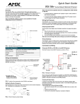
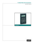
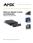
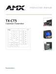
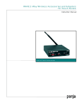
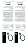
instruction manual
AV2SM
A/V Switcher
C on t ro l S y s t em A c c e s s or ie s
AMX Limited Warranty and Disclaimer
AMX Corporation warrants its products to be free of defects in material and workmanship under normal use for
three (3) years from the date of purchase from AMX Corporation, with the following exceptions:
•
Electroluminescent and LCD Control Panels are warranted for three (3) years, except for the display and touch
overlay components that are warranted for a period of one (1) year.
•
Disk drive mechanisms, pan/tilt heads, power supplies, MX Series products, and KC Series products are
warranted for a period of one (1) year.
•
Unless otherwise specified, OEM and custom products are warranted for a period of one (1) year.
•
Software is warranted for a period of ninety (90) days.
•
Batteries and incandescent lamps are not covered under the warranty.
This warranty extends only to products purchased directly from AMX Corporation or an Authorized AMX Dealer.
AMX Corporation is not liable for any damages caused by its products or for the failure of its products to perform.
This includes any lost profits, lost savings, incidental damages, or consequential damages. AMX Corporation is not
liable for any claim made by a third party or by an AMX Dealer for a third party.
This limitation of liability applies whether damages are sought, or a claim is made, under this warranty or as a tort
claim (including negligence and strict product liability), a contract claim, or any other claim. This limitation of
liability cannot be waived or amended by any person. This limitation of liability will be effective even if AMX
Corporation or an authorized representative of AMX Corporation has been advised of the possibility of any such
damages. This limitation of liability, however, will not apply to claims for personal injury.
Some states do not allow a limitation of how long an implied warranty last. Some states do not allow the limitation or
exclusion of incidental or consequential damages for consumer products. In such states, the limitation or exclusion of
the Limited Warranty may not apply. This Limited Warranty gives the owner specific legal rights. The owner may
also have other rights that vary from state to state. The owner is advised to consult applicable state laws for full
determination of rights.
EXCEPT AS EXPRESSLY SET FORTH IN THIS WARRANTY, AMX CORPORATION MAKES NO
OTHER WARRANTIES, EXPRESSED OR IMPLIED, INCLUDING ANY IMPLIED WARRANTIES OF
MERCHANTABILITY OR FITNESS FOR A PARTICULAR PURPOSE. AMX CORPORATION
EXPRESSLY DISCLAIMS ALL WARRANTIES NOT STATED IN THIS LIMITED WARRANTY. ANY
IMPLIED WARRANTIES THAT MAY BE IMPOSED BY LAW ARE LIMITED TO THE TERMS OF THIS
LIMITED WARRANTY.
Table of Contents
Table of Contents
Product Information .................................................................................................1
Specifications .................................................................................................................... 1
Installation .................................................................................................................3
Automatic and Manual Switching Mode Settings .............................................................. 3
Wiring Guidelines .............................................................................................................. 4
Preparing captive wires............................................................................................................ 4
Video output connector ............................................................................................................ 4
Audio output connector ............................................................................................................ 5
Video A and B input connectors............................................................................................... 5
Audio A and B Input connectors............................................................................................... 5
AV2SM A/V Switcher
i
Table of Contents
ii
AV2SM A/V Switcher
Product Information
Product Information
The AV2SM A/V Switcher is a media interface device you can set to automatically or manually
switch between two A/V input sources, outputting to a display monitor connected to the front
panel.
OUTPUT
VIDEO OUTPUT
connector
GND
GND
LEFT
AUDIO
12 VDC
RIGHT
VIDEO
Front
12 VDC
power supply
connector
AUDIO OUTPUT
connector
VIDEO A and B INPUT
connectors
GND
GND
AUDIO
LEFT
GND
GND
GND
LEFT
VIDEO
RIGHT
INPUT B
AUDIO
RIGHT
INPUT A
VIDEO
Rear
AUDIO A and B INPUT
connectors
FIG. 1 Front and rear panel components of the AV2SM A/V Switcher
Specifications
Specifications
Dimensions (HWD)
1.65" x 5.09" x 6.09" (4.19 cm x 12.93 cm x 15.47 cm)
Weight
10.09 oz (286.05 g)
Power Consumption
4.8 W maximum
Bandwidth
Video - 8 MHz
Audio - 30 Hz to 20 kHz
Video Sync Sense - 15.75 kHz
Sensing - 1 kHz to 3 MHz (300 mVrms minimum and 3 MHz to 20 MHz)
(700 mVrms minimum)
Front Panel:
VIDEO OUTPUT
AV2SM A/V Switcher
BNC female connector
AUDIO OUTPUT
4-pin cable jack
12 VDC
2-pin 12 VDC connector @ 40 mA maximum for external power supply.
The AV2SM can also be powered from an Axcess Central Controller.
1
Product Information
Specifications (Cont.)
Rear Panel:
INPUT A VIDEO
BNC female connector
INPUT A AUDIO
6-pin cable jack, audio and control input
INPUT B VIDEO
BNC female connector
INPUT B AUDIO
4-pin cable jack
Captive-wire screw terminals Allows stereo (unbalanced) line-level audio
Switching Modes:
Automatic
AV2SM switches to the A source; if no input is detected the AV2SM automatically switches to the B source. If both A and B sources are present, the
default is the A source.
Manual
AV2SM determines which source to use based on the state of the SELECT
pin on the rear panel.
Enclosure
Molded black matte plastic
Included Accessories
• Two 4-pin cable connectors
• One 6-pin cable connector
• One 2-pin power connector
Optional Accessories
2
AC-RK Accessory Rack Kit
AV2SM A/V Switcher
Installation
Installation
You can install the AV2SM on any flat surface that has unobstructed access to both the front and
rear panel connectors.
Automatic and Manual Switching Mode Settings
You can select the switching mode by setting two internal jumpers on the circuit card inside the
enclosure. You will need a Phillips screwdriver to open the enclosure. To set the switching mode:
1. Discharge the static electricity from your body and screwdriver.
2. Unplug all connectors from the front and rear panel of the AV2SM.
3. Turn the enclosure upside down and remove the two Phillips-head screws.
4. Pull the enclosure apart and turn the bottom half, containing the circuit card, right-side up.
5. Choose the desired switching mode:
!
E2
2
AUTO
AUTO
For automatic mode (FIG. 2), place the 2-pin jumper on the E1 connector pin’s one and
two. Repeat for the E2 connector.
E1
E1
MAN.
MAN.
FIG. 2 Automatic mode settings
!
E2
2
AUTO
AUTO
For manual mode (FIG. 3), place the 2-pin jumper on the E1 connector pin’s 2 and 3.
Repeat for the E2 connector.
E1
E1
MAN.
MAN.
FIG. 3 Manual mode settings
AV2SM A/V Switcher
3
Installation
Wiring Guidelines
The maximum wiring distance between the Central Controller and the AV2SM is determined by
power consumption, supplied voltage, and the wire gauge used for the cable. The maximum wiring
lengths for using AXlink power are based on a minimum of 13.5 volts available at the Central
Controller’s power supply. The maximum lengths allowable between the AV2SM and the Central
Controller are as follows:
Wiring Guidelines
Wiring size Maximum wiring length
18
1805.7 ft (550.37 m)
20
1142.4 ft (382.20 m)
22
712.2 ft (217.07 m)
24
448.9 ft (136.82 m)
Preparing captive wires
1. Strip 0.25 inch of wire insulation off all wires.
2. Insert each wire into the appropriate opening on the connector according to the wiring
diagrams and connector types described in this section.
3. Tighten the screws to secure the wire in the connector. Do not tighten the screws excessively;
doing so may strip the threads and damage the connector.
Video output connector
Connect your output display monitor to the VIDEO connector on the front panel using FIG. 4.
Video Cable
AV2SM video
output
connector
(female)
Output
display
monitor
connector
(female)
BNC connectors (male)
FIG. 4 VIDEO OUTPUT wiring diagram
4
AV2SM A/V Switcher
Installation
Audio output connector
Connect your output display monitor to the Audio connector on the front panel using FIG. 5.
LEFT
LEFT
GND
GND
GND
GND
RIGHT
Audio source
output
RIGHT
AV2SM AUDIO
INPUT connector
FIG. 5 AUDIO OUTPUT wiring diagram
Video A and B input connectors
Connect your Video Output source to the Input A and B Video connector on the rear panel using
FIG. 6.
Video Cable
AV2SM video
input A and B
connectors
(female)
Video input
source
connector
(female)
BNC connectors (male)
FIG. 6 VIDEO INPUT A and B wiring diagram
Audio A and B Input connectors
Connect the two Audio Output sources to the Input A and B Audio connectors, FIG. 7 illustrates
the automatic switching mode; FIG. 8 shows the wiring for manual switching mode. When you use
manual switching mode, the Select pin (rear panel) is taken low to select the B source and high to
select the A source. A low can be an external relay closure or a voltage level from 0 VDC to 0.8
VDC. A high can be an open set of contacts or a voltage level from 3.3 VDC to 12.0 VDC.
LEFT
SELECT
LEFT
LEFT
GND
GND
GND
GND
RIGHT
GND
Output
(audio source)
RIGHT
GND
AV2SM
AUDIO INPUT A
LEFT
LEFT
GND
GND
GND
GND
RIGHT
Output
(audio source)
RIGHT
AV2SM
AUDIO INPUT A
FIG. 7 AUDIO INPUT A and B wiring diagram for automatic switching mode
AV2SM A/V Switcher
5
Installation
SELECT
LEFT
GND
GND
RIGHT
GND
SELECT
LEFT
GND
GND
RIGHT
Output
(audio
source)
GND
External
relay
closure
AV2SM
AUDIO INPUT A
LEFT
GND
GND
RIGHT
LEFT
GND
GND
RIGHT
Output
(audio source)
AV2SM
AUDIO INPUT B
FIG. 8 AUDIO INPUT A and B wiring diagram for manual switching mode
6
AV2SM A/V Switcher
Installation
AV2SM A/V Switcher
7
brussels • dallas • los angeles • mexico city • philadelphia • shanghai • singapore • tampa • toronto • york
3000 research drive, richardson, TX 75082 USA • 469.624.8000 • 800.222.0193 • fax 469.624.7153 • technical support 800.932.6993
041-004-1101 9/01 ©2001 AMX Corporation. All rights reserved. AMX, the AMX logo, the building icon, the home icon, and the light bulb icon are all trademarks of AMX Corporation.
AMX reserves the right to alter specifications without notice at any time. *In Canada doing business as Panja Inc.
AMX reserves the right to alter specifications without notice at any time.