1
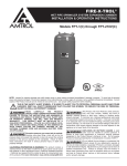
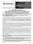
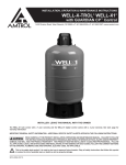
AMTROL PRESSURISER® WATER PRESSURE BOOSTER SYSTEM WITH GUARDIAN CP™ CONTROL INSTALLATION & OPERATION INSTRUCTIONS Models RP-10HP, RP-15HP and RP-25HP NOTE: Inspect for shipping damage. Notify freight carrier or store where purchased immediately if damage is present. To avoid risk of personal injury and property damage, if the product appears to be malfunctioning or shows signs of corrosion, call a qualified professional immediately. Current copies of the product manual can be viewed at www.amtrol.com. Use proper safety equipment when installing. THIS IS THE SAFETY ALERT SYMBOL. IT IS USED TO ALERT YOU TO POTENTIAL PERSONAL INJURY AND OTHER HAZARDS. OBEY ALL SAFETY MESSAGES THAT FOLLOW THIS SYMBOL TO REDUCE THE RISK OF PERSONAL INJURY AS WELL AS PROPERTY DAMAGE. USE ONLY WITH POTABLE WATER SYSTEMS. Do not operate in a setting with freezing temperatures or where the temperature can exceed 200°F and do not exceed the maximum working pressure specified for this Product. READ CAREFULLY THE PRODUCT INSTALLATION & OPERATION INSTRUCTIONS. FAILURE TO FOLLOW THE INSTRUCTIONS AND WARNINGS MAY RESULT IN SERIOUS OR FATAL INJURY AND/OR PROPERTY DAMAGE, AND WILL VOID THE PRODUCT WARRANTY. THIS PRODUCT MUST BE INSTALLED BY A QUALIFIED PROFESSIONAL. FOLLOW ALL APPLICABLE LOCAL AND STATE CODES AND REGULATIONS. IN THE ABSENCE OF SUCH CODES, FOLLOW THE CURRENT EDITIONS OF THE NATIONAL PLUMBING CODE AND NATIONAL ELECTRIC CODE, AS APPLICABLE. This Product, like most Products under pressure, may over time corrode, weaken and burst or explode, causing serious or fatal injury, leaking or flooding and/or property damage. To minimize risk, a licensed professional must install and periodically inspect and service the Product. A drip pan connected to an adequate drain must be installed if leaking or flooding could cause property damage. Do not locate in an area where leaking could cause property damage to the area adjacent to the appliance or to lower floors of the structure. CALIFORNIA PROPOSITION 65 WARNING! This product contains a chemical known by the State of California to cause cancer and to cause birth defects or other reproductive harm. (California Installer/Contractor - California law requires that this notice be given to consumer/end user of this product.) For more information: www.amtrol.com/prop65.html RUPTURE OR EXPLOSION HAZARD. Do not expose Product to freezing temperatures or temperatures in excess of 200°F. Do not adjust the pre-charge or re-pressure this Product except during installation or regular inspection. Replace the Product and do not adjust the precharge if corroded, damaged or with diminished integrity. Adjustments to pre-charge must be done at ambient temperature only. Failure to properly size the Product or follow these instructions may result in excessive strain on the system and may lead to Product failure, serious or fatal personal injury, leakage and/ or property damage. A relief valve must be installed to prevent pressure in excess of local code requirement or maximum working pressure designated in the Product Manual, whichever is less. At least once every 3 years or if discharge is present, a licensed contractor should inspect the temperature and pressure relief valve and replace if corrosion is evident or the valve does not function. FAILURE TO INSPECT THIS VALVE AS DIRECTED COULD RESULT IN UNSAFE TEMPERATURE OR PRESSURE BUILD-UP WHICH CAN RESULT IN PRODUCT FAILURE, SERIOUS INJURY OR DEATH AND/ OR SEVERE PROPERTY DAMAGE AND VOID THE PRODUCT WARRANTY. Chlorine & Aggressive Water: The water quality can significantly influence the life of this Product. You should test for corrosive elements, acidity, total solids and other relevant contaminants, including chlorine and treat your water appropriately to insure satisfactory performance and prevent premature failure. PLEASE READ THE FOLLOWING INSTRUCTIONS CAREFULLY IMPORTANT GENERAL SAFETY INFORMATION ADDITIONAL SPECIFIC SAFETY ALERTS APPEAR IN THE FOLLOWING INSTRUCTIONS. If the control is set too high or the pump is running when the water supply is shut off and there is no demand on the system, the pump will run continuously, can overheat and become damaged, potentially resulting in product failure, leaking and/or rupture. All wire and fuse sizings are preliminary recommendations only. For your safety, local codes, and in their absence, national codes must be followed to minimize the risk of electric shock, property damage or personal injury. The pump motor is designed for use with single phase, 60Hz ac. Use with any other type of power will cause damage to the motor. The pump models RP-10HP, RP-15HP and RP25-HP are pre-wired for 115 vac; however, they can be rewired to be used with 230 vac. Consult motor nameplate for the wiring diagram. The power for your pump must be on a dedicated circuit. In addition, a shut off switch should be visible and near the pump. Use a 20 amp circuit. Sizing Chart Grounding of the pump is essential for your protection and the protection of the motor. All wiring should be completed by a licensed electrician, and in accordance with local codes or in their absence, the National Electrical Code. Before starting the wiring installation, disconnect all power to the circuit to be used for the AMTROL Pressuriser®. The AMTROL Pressuriser® should only be connected to a municipal, cold water supply, and in systems with a minimum pressure of 10 psig at all times, measured under flow at the tap closest to the location of the AMTROL Pressuriser® installation. Installation Amtrol Pressuriser® Minimum Flow Rate From City Supply Minimum Flow Pressure From City Supply Minimum Incoming Pipe Size Water Meter RP-10HP 10 gpm 10 psig 3/4" 3/4" RP-15HP 15 gpm 10 psig 1" 1" RP-25HP 25 gpm 10 psig 1 1/4" 1 1/4" Metal piping must be used for all inlet and outlet lines to the unit. Do not oversize pump. Inadequate water supply will result in poor performance and pump damages. Pre-Installation • DO NOT USE FOR PRE-HEATED WATER SUPPLIES; • DO NOT USE FOR ANYTHING EXCEPT COLD WATER (AMBIENT TEMPERATURE NOT TO EXCEED 100° F); • DO NOT USE IN SYSTEMS WHERE LOW PRESSURE IS DUE TO LEAKS OR WHERE LEAKS IN THE PLUMBING SYSTEM MAY EXIST; • DO NOT USE IN SYSTEMS WHERE THE WATER SUPPLY CAN DROP BELOW 10 PSIG; • DO NOT USE IN SERIES WITH ANOTHER PUMP (SUCH AS IN PRIVATE WELL WATER SYSTEMS); • DO NOT RE-PRESSURIZED TANK AFTER INITIAL INSTALLATION; • DO NOT PIPE EXCEPT WITH METAL PIPING AT INLET AND OUTLETS. The system must be placed indoors only on a solid level surface with a drip pan piped to a drain with adequate capacity for large volumes of water in the event the system ruptures or fails. Consider the risks posed by tanks under pressure and the potential for leaking and/or flooding damage in selecting the location. The unit must not be placed in an environment that would expose the water in the tank to temperatures below freezing or in excess of 100° F. Figure 1 Be sure to leave a minimal clearance of 12” around the unit for access should field adjustments be necessary in the future and to permit maintenance and inspection (Figure 1). Before attempting any service and disassembly, shut off power to the pump. Ensure power is disconnected prior to removing motor. Ensure power is disconnected before cleaning is attempted. 1. Remove protective air valve cap. 2. Check pre-charge pressure (pressure should be + or – 10% of the factory setting). Factory pre-charge is 38 psig. 3. Release or add air as necessary to make the pre-charge pressure 2 psig below the pressure switch pump cut-in setting. 4. Replace protective air valve cap. (Remove air valve label, replace protective air valve cap, peel off backing of label and apply on air valve cap.) MINIMUM SUPPLY LINE AND METER SIZE FOR THE RP-10HP IS 3/4", THE RP-15HP IS 1" AND THE RP-25HP IS 11/4". THIS APPLIES TO ALL LINES INCLUDING THOSE USED WITH THE WATER METER OR FITTINGS BEFORE THE PUMP. CONTACT FACTORY IF MINIMUM FITTING/LINE SIZE IS BELOW THE ABOVE NUMBERS. 5. Install a SPRING LOADED CHECK VALVE in the city supply line on the suction side of the pump along with a shut-off valve. Failure to do so will result in premature failure of the AMTROL Pressuriser due to excessive pump cycling. 6. Install a by-pass loop (Figure 2). Figure 2 BYPASS LOOP TO SYSTEM FLOW SHUT-OFF VALVES RP-10HP RP-15HP RP-25HP PRESSURE RELIEF VALVE CITY WATER SUPPLY SPRING CHECK VALVE FLOW 12" Amtrol Pressuriser® 7. Pipe the city supply after the shut-off valve to the suction side of the pump, as shown. 8. Connect the house supply line using a 100 psig maximum relief valve as shown (Figure 2). It is important that the pressure relief valve be installed on the pump discharge prior to any shut off valves. ELECTROCUTION HAZARD. DISCONNECT ALL ELECTRICAL POWER BEFORE SERVICING. THE GUARDIAN CP™ MUST BE ELECTRICALLY GROUNDED. The Guardian CP™ will operate on 115 vac & 230 vac systems. 9.Disconnect power and verify with a volt meter. 10.Determine the pump electrical requirements. If unknown, contact the pump manufacturer. 11.Select the appropriate wire gauge per local codes and the pump manufacturer’s recommendation. All pumps are 1/2 horsepower and are rated at 10.6 amps for 115 volts and 5.3 amps for 230 volts. 12.Loosen the captive fastener on the top of the controller and remove the plastic cover, exposing the wire leads. (When reassembling cover, do not over-tighten fastener.) 13.Following all electrical codes, wire the Guardian CP (Figure 3.) ™ The Guardian CP™ has openings to accept standard conduit terminations. DO NOT INSTALL ON ELECTRICAL SERVICE RATED ABOVE 20 AMPS. 14.Close the bypass valve. Figure 3 Programming the Guardian CP™ Differential pressure should be adjusted to no greater than 35 psi nor lower than 10 psi. The 20 psi factory differential is recommended. 1.Press and hold . When LO appears, release. This will determine the pressure at which the pump activates. 2. When number appears, tap or to change cut-in setting. 3.Press again. When HI appears, tap or to change cutout setting. This will determine the pressure at which the pump shuts off. 4. Press a third time. The last Error Code in memory will display (see Error Code table in Troubleshooting section). If no errors have occurred, the display will show - 5.After approximately 10 seconds Pr will appear, indicating the settings are programmed. Display will then revert to the line pressure. NOTE: The settings will now be stored until changed manually, even in the event of power failure. NOTE: If pump cannot reach cut-out setting within 5 minutes with no water running, lower the pressure settings to fall within the pump’s pressure capabilities Operation ENSURE THE SWITCH IS OPERATING PROPERLY. AFTER MAKING ANY ADJUSTMENTS, OBSERVE AT LEAST ONE PUMP CYCLE TO VERIFY PROPER PUMP SHUT-OFF. BASIC GUARDIAN CP™ WIRING P2 White w/Black White L2 Blue P1 L1 Black Factory wiring to pump 15.Open the city water supply line valve and a faucet and check the system for leaks, repair any leaks before proceeding. 16.Shut off the faucet and check the system for leaks. Repair any leaks before proceeding. IF THE CONTROL SWITCH IS SET TOO HIGH OR THE PUMP IS RUNNING WHEN THE WATER SUPPLY IS SHUT OFF AND THERE IS NO DEMAND ON THE SYSTEM, THE PUMP WILL POTENTIALLY RUN CONTINUOUSLY, CAN OVERHEAT AND CAUSE DAMAGE; RESULTING IN PRODUCT FAILURE, LEAKING AND/OR RUPTURE. TO REDUCE THIS RISK, NEVER EXCEED 80 PSIG CUTOUT. Start-Up BEFORE CONTINUING, ENSURE THAT ALL WIRING IS COMPLETED AND THE UNIT IS GROUNDED. CHECK FOR OPEN DRAIN VALVES OR OTHER SOURCES OF FLOODING BEFORE STARTING UNIT. 1.Prime pump if necessary and adjust tank precharge to manufacturer’s recommendation for intended pressure range. The factory Guardian CP setting is 40 psi cut-in and 60 psi cut-out. 2. Turn on power and ensure Guardian CP display illuminates. Display will blank momentarily and the pump will start. If not, check installation. 3. The display will now read the current line pressure. 4. Allow the pump to reach the factory cut-off setting of 60 psi. IF THE PUMP CANNOT REACH THIS SETTING, DISCONNECT POWER AND SEE THE TROUBLESHOOTING SECTION. 5. Check for leaks and repair as necessary. Please contact AMTROL Technical Support at 401-535-1216 or an AMTROL representative if further assistance is required. Winterizing: To drain, disconnect the pump from power and open a faucet to bleed off water pressure. Lay the tank on its side to disconnect the piping between the pump and tank to completely drain the unit. Ensure exposed piping conected to unit is also drained. DO NOT ADJUST PRESSURE OR RE-PRESSURIZE THIS PRODUCT EXCEPT FOR ANY ADJUSTMENTS MADE AT THE TIME OF INITIAL INSTALLATION WHEN THE UNIT IS NEW. RE-PRESSURIZATION OF A WEAKENED, DAMAGED, OR CORRODED UNIT CAN CAUSE AN EXPLOSION, POSSIBLY CAUSING SERIOUS OR FATAL PERSONAL INJURY AND/OR PROPERTY DAMAGE. If pressure adjustments are necessary because of changes in inlet pressure, check the condition of the unit first to make sure there is no corrosion of the tank or any connected lines or fittings. Take appropriate precautions. Never adjust the pressure if water is leaking from the air stem. Replace any damaged or corroded tank. Also, air loss is an indication that damage, corrosion or weakening of the unit may have occurred and it should not be re-pressurized. Maintenance Your AMTROL Pressuriser unit, including the pump, must be periodically inspected by an experienced professional for signs of damage, corrosion and leaking. The pump should be checked to ensure it is turning on and off at the appropriate cut-in and cut-out points. At a minimum, after installation, a thorough inspection of all components should take place annually. However, note that units in settings with frequent use, where corrosion, high humidity or aggressive water is more likely to occur, and as the unit ages, should be inspected more frequently. Warranty Two (2) Year Limited Warranty Visit www.amtrol.com for complete warranty details. Troubleshooting The Guardian CP™ incorporates built-in diagnostics. If the AMTROL Pressuriser® is not functioning properly or is inoperable, look for a error code (example E1) on the digital readout before proceeding. Error codes are listed in the table at the bottom of this page. PROBLEM Pump will not start. Pump runs but will not build pressure. Pump builds pressure but will not shut off. CAUSE SOLUTION 1. No Power. 1. Check circuit breaker and fuses, tighten connections. 2. Faulty wiring. 2. Check wiring per installation diagram in this booklet. If pump hums, but will not start, check pump motor wiring (115/230V). 3. Damaged motor. 3. If display illuminates with no error code, but pump will not start, replace pump. 4. Damaged control. 4. If power is present at L1/L2 but display is blank, replace control. 1. Supply closed/blocked. 1. Open all supply valves, ensure check valve is not sticking, clean any filters. 2. Bypass loop open. 2. Close bypass valve. 3. Pump plumbed backwards. 3. Reverse inlet/outlet. 4. Bad internal parts. 4. Check for bad seals or broken impeller. Repair or replace as necessary. 1. Operating pressure set too high. 1. Reduce control setting as necessary. 2. Bad internal parts. 2. Check for bad seals or broken impeller. Repair or replace as necessary. 3. Control line blocked. 3. Remove control line and blow compressed air to clear. 1. Control differential too narrow. Pump starts too often 2. Tank precharge incorrect. (cycles under 30 sec.). 3. Waterlogged pressure tank. 1. Set cut-in and cut-out 20 psi apart. 2. Set air pressure 2 psi below cut-in while pump is off and gauge pressure is zero. 3. If water emerges from tank air stem when depressed, replace tank. To reset control at any time, press buttons simultaneously for 5 seconds. To "invert" the display for easier viewing, press together for 3 seconds. CODE E1 REASON ACTION CAUSE & REMEDY Rapid cycle Excessive amp draw Switch continues to operate. See “Pump Starts Too Often” above. Have pump checked for proper operation. E2 Low-suction (running pressure) below 10 PSI Shuts off pump. Auto restart after 60 min. 1. Determine cause of low-suction. 2. Check Wiring. 3. Inspect pump. E3 Improper voltage Shuts off pump. Restore voltage to proper range. Pump automatically restarts with proper voltage. THE GUARDIAN CP CONTROL CONTAINS NO SERVICEABLE PARTS. REMOVAL OF MAIN CIRCUIT BOARD COVER WILL VOID WARRANTY. LOW-LEAD © 2014 AMTROL Inc. 1400 Division Road, West Warwick, RI USA 02893 T: 800.426.8765 F: 800.293.1519 www.amtrol.com Mark of the Originator Part #: 9040B140 (07/14)