1
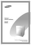
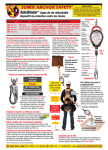
ATM 300 Series
Tape Recorder Interface
Installation and Operation
™
1308903-02
NOTICE
The contents of this technical manual have been checked and are believed to be accurate. However, no
responsibility is assumed for any inaccuracies in the information provided herein. Ampex Corporation
reserves the right to make changes without notice to improve reliability, function or design.
TRADEMARKS
DIS is a registered trademark of Ampex Corporation.
Prepared by Technical Publications
Ampex Corporation
500 Broadway
Redwood City, CA 94063-3199
Copyright © 1998 by Ampex Corporation
All rights reserved
Part No. 1308903-02
Issued: March 1998
Technical Information
Customer Support
Ampex provides extensive customer support for its products. These services are outlined below. When
requesting services, please supply the following information (most of which can be found on the
identification name plate located on the system’s rear panel) to help expedite your request.
•
•
•
•
•
Model
Serial Number
Catalog/part number
Date of purchase
Name and address of your organization
Field Service
For service quotations and scheduling, call the Ampex Customer Service Center at 800-DST-SRVC
(800-378-7782) or 719-596-2000.
Parts and Accessories
Within the United States, call 800-227-8402 for information and quotations on replacement parts, lists of
spares, and accessories to use with your system. Outside the United States, call 719-570-3DST
(719-570-3378) in Colorado Springs, Colorado, USA or fax 719-570-3289.
Technical Support
If you require information or technical assistance that is not available in your local area, contact the
Ampex Customer Service Department for assistance:
Ampex Corporation Customer Service
600 Wooten Road
Colorado Springs, CO 80915-3597
Telephone: 800-DST-SRVC (800-378-7782) or 719-570-3378
Fax: 719-570-3289
International Telephone: 719-570-3378
E-mail address: [email protected] (USA) or [email protected] (UK)
Website:
http://www.ampex.com
Training Services
Ampex offers technical (maintenance) training on this and other data storage products on a scheduled
basis. For further information regarding training, call :
800-227-8402
719-570-3714
719-570-3329 (FAX).
iii
Safety and First Aid Suggestions
No matter how well electrical equipment is designed, you can be exposed to dangerous electrical shock when
protective covers are removed for service or other activities. Therefore, you should consistently observe all
safety regulations, be sure that you thoroughly understand the dangers related to electrical hazards, and have
some knowledge of first aid required for electrical injuries. In addition, follow these general safety practices:
Do not touch or adjust unprotected circuit controls or dress
leads with the power on.
Always avoid placing parts of the body in series between
ground and circuit points.
To avoid burns, do not touch heavily loaded or overheated
components without taking precautions.
Remember that some semiconductor cases and solid-state
circuits carry high voltages.
Do not assume there is no danger of electrical shock when
power is off. Charged capacitors can retain high voltages for a
long time after power is turned off. You should discharge
capacitors through a suitable resistor before touching any
circuit points.
Don’t take chances. Be fully trained. Only qualified personnel
should operate and maintain Ampex equipment.
Muscular spasm or unconsciousness can prevent a victim from freeing himself from the electrical power. If
someone appears to have received an electrical shock, turn power off before attempting first aid.
DANGER!
Do not touch electrical shock victims or their clothing
before disconnecting power. You can also become a shock
victim.
iv
Good Practices
If you cannot turn off power immediately, very carefully loop a length of dry, nonconducting material
(such as rope, insulating material, or clothing) around the victim and pull him free of the power. Avoid
touching the victim or victim’s clothing until free of power. Immediately start the appropriate first aid
procedures.
When testing or servicing the equipment described in this manual, keep in mind the following standard
good practices:
When connecting any instrument (oscilloscope,
waveform monitor, etc.) to a high-frequency output,
use the appropriate termination resistor at the input
of the instrument unless the instrument is terminated
internally.
When inserting or removing printed wiring
assemblies (PWAs), cable connectors, or fuses,
always turn off power to the affected portion of the
equipment. After removing power, allow sufficient
time for the power supplies to bleed down before
reinserting PWAs.
To avoid damage to PWA components from static
electricity, use standard static-safe handling
procedures such as wearing a grounded wrist strap
and working on grounded conductive surfaces.
v
Notice!
This equipment generates, uses, and can radiate
radio frequency energy. If not installed and used in
accordance with the instruction manual, it may cause
interference to radio communications.
This equipment has been tested and found to comply
with the limits for a Class A digital device pursuant
to part 15 of FCC rules, which are designed to
provide reasonable protection against such
interference when operated in a commercial
environment. Operation of this equipment in a
residential area is likely to cause interference, in
which case the users will be required to correct the
interference at their own expense.
This system was tested using the shielded
interconnect cables provided with the unit. Failure to
use the cables provided may result in radio
interference outside acceptable limit
vi
ATM 300 Series
Contents
Contents
1.0
1.1
1.2
1.3
1.4
1.5
1.6
1.7
1.8
Ampex 1308903-02
Introduction .......................................................................................................1
Description ........................................................................................................1
Unpacking and Inspection .................................................................................2
Rack Mounting ..................................................................................................2
Data Connections ..............................................................................................2
Multiple ATM 300S/M Connections ................................................................3
Switches and Indicators .....................................................................................5
Operation ...........................................................................................................6
Self-Test ............................................................................................................6
vii
ATM 300 Series
1.0
Introduction
Introduction
This manual describes how to install and operate the Ampex ATM 300 Series Tape Recorder
Interface.
1.1
Description
Ampex provides three models of the ATM 300 Series Tape Recorder Interface:
•
•
•
ATM 300 - Multimode fiber physical layer interface
ATM 300S - Singlemode fiber physical layer interface with SyncStart
ATM 300M - Multimode fiber physical layer interface with SyncStart
These three units convert OC-3 (Optical Carrier) data to HOTLink™ serial data for recording
to an Ampex DIS tape drive. During playback, the units convert HOTLink serial data from the
DIS tape drive to OC-3 optical data at a continuous 19.44 megabytes (MB) per second.
Figure 1 shows a typical single unit configuration.
RECORD
IN
ASYCHRONOUS
TRANSFER
MODE (ATM)
SWITCH
ATM 300 SERIES
HOTLINK
OUT
DIS 160i/162i
TAPE DRIVE OR
DIS 260i/262i/860i/862i
ACL
PLAY
FIBER OPTIC DEVICE
Figure 1. Typical Configuration
Table 1 lists the ATM 300 specifications.
Table 1. Specifications
Parameter
Data Interfaces
Fiber Optic
Electrical Serial
Specification
ATM (Asynchronous Transfer Mode), OC-3 (Optical Carrier) and
SONET formats
Cypress HOTLink
Data Transfer Rate
OC-3
HOTLink
19.44 MB/sec (155.52 Mbits/sec)
0-32 MB/sec (0-256 Mbits/sec)
Optical Wavelength
1300 nm
Optical Connectors
Duplex SC
Ampex 1308903-02
1
Model
No.
ATM 300
Series
Running Head
Unpacking
and Inspection
Table 1. Specifications (Continued)
Parameter
1.2
Specification
Optical Data Cables
62.5/125 µm multimode fiber (ATM 300 and ATM 300M)
8.3/125 µm singlemode fiber (ATM 300S)
Electrical Data Cables
Ampex provides the following accessory cable kits:
Ampex Part No.
Size
1308564-01
120-in (305 cm) - standard
1308565-01
180-in (457 cm)
1308566-01
300-in (762 cm)
1308567-01
600-in (1524 cm)
SyncStart Connector
BNC
Power Requirements
100-240 Vac, 47-63 Hz single phase, 150 watt maximum
Dimensions
19” (480 mm) rack mountable
17.0” W x 1.875” H x 8.0” D (432 mm x 48 mm x 203 mm)
Unpacking and Inspection
Perform the following inspection upon receipt of the unit:
1. Unpack and check the unit for shipping damage. If equipment is damaged notify the
carrier immediately.
2. Check equipment received against the packing list to ensure that the shipment is complete.
If any shortages exist, promptly contact the sales representative.
1.3
Rack Mounting
Ampex ships the ATM as a desk top unit. However, the unit can be mounted into a standard
19-inch (284 mm) rack using the hardware provided. To mount the unit into a rack, install the
two brackets on either side of the unit using the four machine screws provided. Then, mount
the completed assembly to the rack rails.
1.4
Data Connections
The ATM unit provides fiber optic connectors on the front panel and HOTLink connectors on
the rear panel. Figure 2 shows the cable connections. See Table 1 for cable specifications.
2
Ampex 1308903-02
ATM 300 Series
Multiple ATM 300S/M Connections
FRONT PANEL
REAR PANEL
OUT
RECEIVER
FIBER OPTIC
DEVICE
HOTLINK
INTERFACE
TRANSMITTER
SERIAL IN
DIS 160i
IN
SERIAL OUT
ATM 300 SERIES
NOTE: SEE TABLE 1 FOR CABLE AND CONNECTOR SPECIFICATIONS.
Figure 2. Single OC-3 Connection
1.5
Multiple ATM 300S/M Connections
To synchronize data transfers to and from the multiple tape drives, connect a user supplied
SyncStart signal to multiple ATM 300S/M units. The SyncStart signal synchronizes the data
transfers to the tape drives during record, and from the tape drives during playback. Figure 3
shows a record/playback configuration across multiple tape drives with synchronized OC-3
interfaces.
The SyncStart signal is a level sensitive transistor-to-transistor logic (TTL) signal. A high
(high TTL level or no connection) signal enables data to and from the tape drive. A low (low
level TTL or ground) disables data to and from the tape drive. Tie all SyncStart inputs to a
common control signal to synchronize data transfers across multiple tape drives.
The ATM unit internally debounces the SyncStart signal so that the low-to-high transition
enables data to flow immediately. For high-to-low transitions, the unit debounces the signal
for approximately 3 ms before it disables the data flow. Therefore, if you use a toggle switch
or relay to provide a contact closure to ground as the SyncStart input, then the first disconnect
from ground will enable data flow. If the switch or relay is noisy and produces bounces back
to ground, the data flow will remain enabled. Only a 3-ms or greater low level signal will
disable the data flow. (Typically, switch or relay contacts open with much less noise than when
they are closed.)
Ampex 1308903-02
3
Model
No.
ATM 300
Series
Running Head
Multiple
ATM 300S/M Connections
FRONT PANEL
REAR PANEL
OUT
RECEIVER
FIBER OPTIC
DEVICE
SERIAL IN
HOTLINK
INTERFACE
TRANSMITTER
DIS 160i
IN
SYNCSTART
SERIAL OUT
ATM 300S/M
FRONT PANEL
REAR PANEL
RECEIVER
OUT
FIBER OPTIC
DEVICE
SERIAL IN
HOTLINK
INTERFACE
TRANSMITTER
DIS 160i
IN
SYNCSTART
SERIAL OUT
ATM 300S/M
FRONT PANEL
REAR PANEL
OUT
RECEIVER
FIBER OPTIC
DEVICE
SERIAL IN
HOTLINK
INTERFACE
TRANSMITTER
IN
SYNCSTART
DIS 160i
SERIAL OUT
ATM 300S/M
SYNCSTART SIGNAL
(TOGGLE SWITCH, RELAY, ETC.)
ENABLE
DISABLE
Figure 3. Multiple OC-3 Connection
4
Ampex 1308903-02
ATM 300 Series
1.6
Switches and Indicators
Switches and Indicators
Table 2 describes the front and rear panel switches and indicators.
Table 2. Switches and Indicators
Panel
Front
Name
DATA FLOW
(switch)
TRANSMITTER
EMPTY
(yellow
indicator)
Rear
Description
Determines how the ATM unit responds to a missing
or invalid OC-3 input.
CONTINUOUS - Continues record and playback
operations at 155.52 Mbits/sec as
determined by an internal crystal
oscillator. This provides a valid OC-3
output during playback regardless of the
OC-3 input status.
GATED - Pauses record and playback operations
until valid OC-3 input is restored.
The ATM unit resumes normal operation after the
OC-3 input is restored.
Indicates data rate from the tape drive is too slow.
This is to be expected whenever the tape drive is not
supplying data.
FULL
(red indicator)
Indicates data rate from the tape drive is too fast. This
is an abnormal condition and most likely indicates
that the tape drive is not using its write input to
regulate its playback rate (internal playback clock*
should be disabled).
OK (green
indicator)
Indicates correct data rate from the tape drive.
RECEIVER OK
(green indicator)
Indicates ATM unit receiving valid OC-3 optical
signal input.
POWER (green
indicator)
Indicates ATM unit is powered-up.
POWER (switch)
ON - Powers up the ATM unit.
OFF - Powers down the ATM unit.
TEST LOOP
(switch)
TEST - Self test operation.
NORMAL - Normal operation.
ERROR (red
indicator)
Indicates (during normal operation) that a valid
HOTLink input is missing.
RESET (button)
Resets the ATM unit during normal operation.
*For setting internal playback clock options, see DIS Tape Drive or ACL Installation and
Operation manual.
Ampex 1308903-02
5
Model
No.
ATM 300
Series
Running Head
Operation
1.7
Operation
To operate the ATM units:
1. For initial installations, perform the self-test procedure in paragraph 1.8.
2. Verify the TEST LOOP switch, on the rear panel, is in the NORMAL position.
3. Place the POWER switch to the ON position. The POWER indicator should light.
4. Verify the ERROR indicator (rear panel) is off.
5. Verify the tape drive is setup for External Playback Clock (see DIS Tape Drive or ACL
Installation and Operation manual).
6. Set the DATA FLOW switch to CONTINUOUS or GATED as required (see Table 2).
7. Perform record or playback operations.
For synchronized data transfers in multiple OC-3 interfaces (see paragraph 1.5) control
the SyncStart signal as follows:
a. For record operations, hold the common SyncStart signal low until all tape drives are
ready to accept data and the desired input data is available. Set the common SyncStart
signal high, to begin delivering data from the ATM units to their respective tape drives.
b. For playback operations, hold the common SyncStart signal low until all tape drives
are ready to deliver data and the unit accepting data is ready. Set the common
SyncStart signal high to begin providing data to the units accepting data.
1.8
Self-Test
To perform the self-test:
1. Loop the fiber optic and HOTLink cables as shown in Figure 4.
FRONT PANEL
REAR PANEL
RECEIVER
OUT
HOTLINK
INTERFACE
TRANSMITTER
HOTLINK LOOP
IN
FIBER OPTIC LOOP
ATM 300
Figure 4. Self-Test
6
Ampex 1308903-02
ATM 300 Series
Self-Test
2. Place the POWER switch to the ON position. The following indicators should be on:
•
•
•
POWER
RECEIVER OK
TRANSMITTER OK
3. Place the TEST LOOP switch to the TEST position.
4. Press the RESET button. The ERROR indicator should go off and remain off indicating
unit is operating properly. If necessary, check cable connections. Otherwise, call your
local Ampex regional office.
Ampex 1308903-02
7
™
Ampex Corporation
500 Broadway
Redwood City, CA 94063-3199
Part Number 1308903-02