1
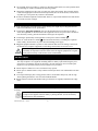
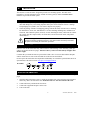
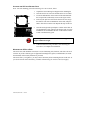
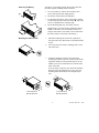
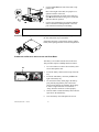
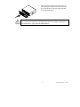
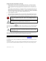
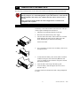
Installation Manual English APC Smart-UPS® 1400 VA 3U Rack and Stack Uninterruptible Power Supply 230 Vac 990-1048, Revision 1 12/00 1: SAFETY INFORMATION American Power Conversion Corporation (APC) is the leading national and international manufacturer of state-of-the-art uninterruptible power supplies, redundant switches, power management software, and related equipment. APC products protect hardware, software, and data from the threat of power disturbances in business and government offices throughout the world. The APC Uninterruptible Power Supply (UPS) is designed to prevent blackouts, brownouts, sags, and surges from reaching your computer and other valuable electronic equipment. The UPS filters out small utility line fluctuations and isolates your equipment from large disturbances by internally disconnecting from the utility line. The UPS provides continuous power from its internal battery until the utility line returns to safe levels. Changes or modifications to this unit not expressly approved by the party responsible for compliance could void the warranty. HANDLING SAFETY The UPS requires two people for installation due to its weight. To lighten the UPS, you may remove the battery while you position or mount it in the rack. Refer to the Operation Manual for instructions on how to remove the battery. <18 kg (<40 lb) 32–55 kg (70–120 lb) >55 kg (>120 lb) 18–32 kg (40–70 lb) n Equipment with casters is built to move on a smooth surface without any obstacles. n Do not use a ramp incline of more than 10°. This equipment is intended for installation in a temperature-controlled indoor area free of conductive contaminants. Refer to Specifications at the APC web site for the actual temperature range. n ELECTRICAL SAFETY n n n n n n Do not work alone under hazardous conditions. High short circuit current through conductive materials could cause severe burns. A licensed electrician is required to install permanently wired equipment. Check that the power cord(s), plug(s), and sockets are in good condition. To reduce the risk of electric shock when grounding, disconnect the equipment from the AC power outlet before installing or connecting to other equipment. Reconnect the power cord only after all connections are made. Do not handle any kind of metallic connector before the power has been removed. 1 990-1048, Revision 1 12/00 Use one hand, whenever possible, to connect or disconnect signal cables to avoid a possible shock from touching two surfaces with different electrical grounds. n Connect the equipment to a three wire AC outlet (two poles plus ground). The receptacle must be connected to appropriate branch circuit/mains protection (fuse or circuit breaker). Connection to any other type of receptacle may result in a shock hazard. n In order to maintain compliance with the EMC directive, output cords attached to the UPS should not exceed 10 meters in length. n DEENERGIZING SAFETY If the equipment has an internal energy source (battery), the output may be energized when the unit is not connected to an AC power outlet. n To deenergize pluggable equipment: first press the OFF button for more than one second to switch the equipment off. Next disconnect the equipment from the AC power outlet, and disconnect the battery. Finally, push the ON button to deenergize the capacitors. n n To deenergize permanently wired equipment: set the power switch to standby . Set the AC circuit breaker to standby , then disconnect the battery (including any expansion units). Finally, disconnect the AC power from the building power supply. n Pluggable equipment includes a protective earth conductor that carries the leakage current from the load devices (computer equipment). Total leakage current must not exceed 3.5 mA. Use of this equipment in life support applications where failure of this equipment can reasonably be expected to cause the failure of the life support equipment or to significantly affect its safety or effectiveness is not recommended. n BATTERY SAFETY n n n n n This equipment contains potentially hazardous voltages. Do not attempt to disassemble the unit. The only exception is for equipment containing batteries. Battery replacement using the procedures below is permissible. Except for the battery, the unit contains no user serviceable parts. Repairs are to be performed only by factory trained service personnel. Do not dispose of batteries in a fire. The batteries may explode. Do not open or mutilate batteries. They contain an electrolyte that is toxic and harmful to the skin and eyes. To avoid personal injury due to energy hazard, remove wristwatches and jewelry such as rings when replacing the batteries. Use tools with insulated handles. Replace batteries with the same number and type of batteries as originally installed in the equipment. BATTERY REPLACEMENT AND RECYCLING See your dealer or the Operation Manual for information on replacement battery kits and battery recycling. Batteries must be recycled. Deliver the battery to an appropriate recycling facility or ship it to the supplier in the new battery’s packing material. See the new battery instructions for more information. 990-1048, Revision 1 12/00 2 2: INSTALLATION The UPS has a “rack and stack” design that provides two mounting options. The UPS can be mounted in a 19-inch equipment rack or stacked on a battery pack(s) model SU24RMXLBP2U. Hardware is provided for either option. UNPACKING 1. Inspect the UPS upon receipt. APC designed robust packaging for your product. However, accidents and damage may occur during shipment. Notify the carrier and dealer if there is damage. The packaging is recyclable; save it for reuse or dispose of it properly. 2. Check the package contents. The shipping package contains the UPS, its front bezel, a mounting kit with brackets, cleats, feet, and hardware, a rail kit containing mounting rails, installation instructions, and a hardware packet (necessary for rack mounting the UPS), a literature kit containing a Utility CD, three output cables, one serial cable, one RJ-45 network cable, and product documentation. The UPS is shipped with the battery and the front bezel disconnected. (The bezel is packaged separately within the main box.) You must connect the battery and install the plastic bezel during the installation procedure. POSITIONING THE UPS Place the rack and the UPS where they will be used for either stacking or rack mounting. (Both procedures are detailed on the next page). The UPS is heavy. Select a location sturdy enough to handle the weight. Consider that you install the UPS in a protected area that is free of excessive dust and has adequate airflow. Ensure the air vents on the front and rear of the UPS are not blocked. Do not operate the UPS where the temperature and humidity are outside the specified limits. Refer to Specifications at the APC web site www.apcc.com/support/contact PLACEMENT S m a r t - U P S S m a r t - U P S S m a r t - U P S INSTALLING THE SMART-UPS To install the Smart-UPS, follow these basic steps. Each step is described in detail on the following pages. 1. Stack the UPS on the battery pack or install the mounting rails in the rack (four-post rack installation only). Place the UPS in the rack. Install the UPS at or near the bottom of the rack. 2. Connect the battery and attach the front bezel. 3. Connect the equipment and power to the UPS. 4. Turn on the UPS. 3 990-1048, Revision 1 12/00 STACKING THE UPS ON A BATTERY PACK Note: For rack mounting, proceed to Mounting the UPS in a Rack, below. 1. Unpack the four mounting feet shipped in the mounting kit. 2. Turn the UPS on its side so the bottom surface is accessible. 3. Locate the indentations on the bottom of the UPS that mark the feet positions (indicated by arrows in the figure at left). 4. Peel away the protective film on the back of one foot, align the adhesive side with an indentation on the UPS, and press hard to affix the foot to the UPS. Repeat this step for all feet. 5. Turn the UPS right side up and place it either on the floor on an optional battery pack (shown). The battery pack cover has indentations to accommodate the feet on the bottom of either a UPS or another battery pack. | 0 B a tte r y P a c k Do not step on the UPS. The UPS chassis is not designed to support additional weight. 6. Continue with Connecting the Battery and Attaching the Front Bezel, to complete the installation. MOUNTING THE UPS IN A RACK The UPS comes with standard 19-inch (46.5 cm) rack mounting rails, brackets, and cleats. The rack can have any of the common types of equipment mounting holes (square, round-threaded, or roundnon-threaded). All necessary hardware is provided. The UPS is heavy. To lighten it, you may remove the battery before mounting the unit in the rack. If you do not want to remove the battery, continue with Mounting the UPS in a Rack (next page). 990-1048, Revision 1 12/00 4 Removing the Battery The battery is accessible from the front of the UPS. This procedure requires a Phillips head screwdriver. 1. Use a screwdriver to remove the two battery door screws and open the door (hinged panel). 2. The battery is disconnected for shipment. 3. To disconnect the battery, take out the white cord that is tucked into the space above the battery . This cord serves as a handle for the connector plug. 4. Be careful during this step—the battery is heavy. Pull the battery out of the UPS by pulling the clear label , not the white cord. (The battery consists of a string of four batteries. The white cord is connected to the battery leads, not the body of the battery.) Mounting the UPS in a Rack 1. Install the mounting rails in the rack (required for four-post racks only). Directions are included with the rail kit. 2. For a four-post rack, attach a mounting cleat to each side of the UPS. 3. Attach the mounting brackets to the UPS before mounting the UPS in your rack, (below). Each mounting bracket attaches to the UPS with four screws (included). Two sets of bracket holes are located on the sides of the UPS. If you are using a four-post rack, attach the mounting brackets in the forward position. For two post rack mounting attach the brackets at the mid-point position. Four-Post Rack Bracket Position Two-Post Rack Bracket Position 5 990-1048, Revision 1 12/00 4. 5. 6. Use the handles on the side of the UPS to support the unit. Due to the weight of the UPS, two people are required to install it in the rack. In four-post mounting each side of the UPS has a cleat that must slide into the groove on the rails. Slide the UPS into position. Use the four ornamental screws supplied with the UPS to attach the mounting brackets to the rack post in both two and four post mounting. Check the rack to make sure it will not tip after loading the UPS into the rack. If you removed the battery before mounting the UPS in the rack, follow this step to reinstall it. Reinstalling the Battery Supporting the battery on the bottom, align it with the battery door opening and slide it into the compartment. CONNECTING THE BATTERY AND ATTACHING THE FRONT BEZEL The battery is accessible from the front of the UPS. This procedure requires a Phillips head screwdriver. 1. Use a screwdriver to remove the two battery door screws and open the door. 2. Locate the battery cables tucked on top of the battery. 3. Locate the UPS battery connector jack to the right of the battery tray. 4. To connect the battery cable plug to the battery jack, push the plug into the jack so the metal pieces inside each part are touching. Press firmly to ensure a tight connection. You will hear a “snap” when the connector is seated properly. 5. Tuck the white cord and the battery cables into the space above the UPS battery. 6. Close the battery door and replace the screws. | 0 990-1048, Revision 1 12/00 6 7. Unpack the bezel and hold it with the cutout section on the right. Align the tabs on the side of the bezel with the slots on the front of the UPS and gently snap it into place. To connect an optional external battery pack(s) to the UPS, refer to the 2U Battery Pack User’s Manual for instructions. This Smart-UPS 1400 XL can support a maximum of ten external battery packs, model SU24RMXLBP2U. 7 990-1048, Revision 1 12/00 CONNECTING POWER AND EQUIPMENT TO THE UPS 1. Plug the UPS into a two-pole, three-wire, grounding receptacle only. Avoid using extension cords and adapter plugs. Your UPS is not supplied with an input line cord. Three output line cords are supplied for connecting equipment (loads). Additional cords are available from your dealer. 2. Swap an input cord from another piece of equipment with one of the supplied output cords. The input cord used for the UPS must be three conductor—1.0 mm2, rated 10 Amps. Use this equipment cord to connect the UPS to utility power. If your equipment does not have a removable line cord, see your dealer or contact APC to obtain a suitable input line cord. Connect equipment to the UPS. 3. Turn on all connected equipment (loads). To use the UPS as a master ON/OFF switch, be sure all connected loads are switched ON. The loads will not be powered until the UPS is turned on. 4. Add any optional accessories. See the documentation accompanying the accessory for details. Use the cable provided with your UPS to connect to the Computer Interface Port. DO NOT use a standard serial interface cable since it is incompatible with the UPS connector. Do not connect a laser printer to the UPS. A laser printer draws significantly more power than other types of equipment and may overload the UPS. TURNING ON THE UPS labeled TEST. This will supply power to the connected equipment. Press and release the button Make sure connected loads are switched to their ON position. The UPS performs a self-test at this time. The UPS charges its battery when it is connected to utility power. The battery charges fully during the first four hours of normal operation. Do not expect full run time during this initial charge period. The unit performs a self-test automatically when turned on and every two weeks thereafter (by default). Refer to the Operation Manual for details on changing the default interval. ACCESSORIES This UPS is equipped with an accessory slot. See the APC website, www.apcc.com for available accessories. If a standard accessory (such as an SNMP card) is installed on this UPS, see the Utility CD for user documentation. For additional computer system security, install PowerChutePlus® Smart-UPS monitoring software. It provides automatic unattended shutdown capabilities on most major network operating systems. 990-1048, Revision 1 12/00 8 3: TRANSPORTING YOUR SMART-UPS The UPS may be transported in or out of the rack. In either case the battery must be disconnected! Always DISCONNECT THE BATTERY before shipping the UPS to avoid damage during transport. (U.S. Federal Regulation requires that batteries are disconnected during shipment.) The battery may remain in the UPS; it does not have to be removed. This requirement applies whether the UPS is shipped alone or installed in an equipment rack or system. DISCONNECTING THE BATTERY The battery is accessible from the front of the UPS. This procedure requires a Phillips head screwdriver. 1. Shut down any equipment attached to the UPS. 2. Disconnect the UPS from the power supply. 3. Face the front of the UPS to remove the bezel. Use both hands and grasp the finger clips on either side of the bezel. Pull toward you. The bezel will unsnap. Set the bezel aside. 4. Use a screwdriver to remove the two battery door screws and open the door. 5. To disconnect the battery, take out the white cord that is tucked into the space above the battery . This cord serves as a handle for the connector. Grasp the cord and pull firmly toward you. 6. Tuck the white cord on top of the battery pack. 7. Close the battery door and replace the two screws removed in Step 4. Leave the front bezel off unless the UPS is being transported in a rack. 9 990-1048, Revision 1 12/00 REMOVING THE UPS FROM THE RACK If your UPS is mounted in a rack and you are removing it from the rack for transport: Remove the four ornamental screws that secure the unit to the rack. Grasp the handle located on the front of the UPS and pull the unit halfway out of the rack. n Use the handles on the sides of the unit for additional support and slide the unit out of the rack. n n 990-1048, Revision 1 12/00 10 4: TROUBLESHOOTING Use the chart below to solve minor UPS installation problems. Contact APC for assistance with complex UPS problems. Refer to the Operation Manual for operational problems. PROBLEM AND POSSIBLE CAUSE SOLUTION UPS WILL NOT TURN ON ON button not pushed. UPS not connected to AC power supply. UPS input circuit breaker tripped. Very low or no utility voltage. Battery not connected properly. Press the ON button once to power the UPS and the load. Check that the power cable from the UPS to the utility power supply is securely connected at both ends. Reduce the load on the UPS by unplugging equipment and resetting the circuit breaker (on the back of UPS) by pressing the plunger in. Check the AC power supply to the UPS by plugging in a table lamp. If the light is very dim, have the utility voltage checked. Check that the battery connector is fully engaged. UPS OPERATES ON-BATTERY ALTHOUGH NORMAL LINE VOLTAGE EXISTS UPS input circuit breaker tripped. Very high, low, or distorted line voltage. Inexpensive fuel powered generators can distort the voltage. Reduce the load on the UPS by unplugging equipment and resetting the circuit breaker (on the back of UPS) by pressing the plunger in. Move the UPS to a different outlet on a different circuit. Test the input voltage with the utility voltage display. If acceptable to the connected equipment, reduce the UPS sensitivity. ALL INDICATORS ARE LIT AND THE UPS EMITS A CONSTANT BEEPING Internal UPS fault. Do not attempt to use the UPS. Turn the UPS off and have it serviced immediately. THE REPLACE BATTERY LED IS LIT Weak battery. Replacement battery not connected properly. Allow the battery to recharge for at least four hours. Then, perform a self-test. If the problem persists after recharging, replace the battery. Check that the battery connector is fully engaged. THERE IS NO AC POWER AND THE UPS HAS BEEN TURNED OFF When the UPS is off and there is no utility power, use the cold start feature to apply power to the connected equipment from the UPS battery. Cold start is not a normal condition. button, (for about 3 seconds). The unit Press and hold the will beep, the LED lights will flash, and the unit will beep a second time. Release the ON button during the second beep. This will supply immediate power to the UPS and the connected loads. Make sure the connected loads are switched to their ON positions. 11 990-1048, Revision 1 12/00 SERVICE If the UPS requires service do not return it to the dealer. Instead follow these steps: 1. Review the problems discussed in Troubleshooting to eliminate common problems. 2. Verify that no circuit breakers are tripped. A tripped circuit breaker is the most common UPS problem. 3. If the problem persists, refer to Contacting APC, next page. Note the model number of the battery pack, the serial number, and the date purchased. If you call Customer Service a technician will ask you to describe the problem and try to solve it over the phone, if possible. If this is not possible the technician will issue a Returned Material Authorization Number (RMA#). n If the UPS is under warranty, repairs are free. If not, there is a repair charge. Pack the UPS in its original packaging. If the original packing is not available, ask customer service about obtaining a new set. n 4. Pack the UPS properly to avoid damage in transit. Never use Styrofoam beads for packaging. Damage sustained in transit is not covered under warranty. Refer to the Installation Manual for important shipping instructions. 5. Mark the RMA# on the outside of the package. 6. Return the UPS by insured, prepaid carrier to the address given to you by Customer Service. 990-1048, Revision 1 12/00 12 5: CONTACT, REGULATORY, AND WARRANTY INFORMATION CONTACTING APC Refer to the information provided at the APC Internet site: http://www.apcc.com/support/contact If you ordered a Smart-UPS SU1400R3XLIX171 unit, refer to the red addendum sheet (part number 990-1023A) for contact information. REGULATORY AGENCY APPROVALS N 394 B geprüfte Sicherheit ME 61 This is a Class A product. In a domestic environment this product may cause radio interference, in which case the user may be required to take corrective actions. 13 990-1048, Revision 1 12/00 LIMITED WARRANTY American Power Conversion (APC) warrants its products to be free from defects in materials and workmanship for a period of two years from the date of purchase. Its obligation under this warranty is limited to repairing or replacing, at its own sole option, any such defective products. To obtain service under warranty you must obtain a Returned Material Authorization (RMA) number from customer support. Products must be returned with transportation charges prepaid and must be accompanied by a brief description of the problem encountered and proof of date and place of purchase. This warranty does not apply to equipment that has been damaged by accident, negligence, or misapplication or has been altered or modified in any way. This warranty applies only to the original purchaser who must have properly registered the product within 10 days of purchase. EXCEPT AS PROVIDED HEREIN, AMERICAN POWER CONVERSION MAKES NO WARRANTIES, EXPRESSED OR IMPLIED, INCLUDING WARRANTIES OF MERCHANTABILITY AND FITNESS FOR A PARTICULAR PURPOSE. Some states do not permit limitation or exclusion of implied warranties; therefore, the aforesaid limitation(s) or exclusion(s) may not apply to the purchaser. EXCEPT AS PROVIDED ABOVE, IN NO EVENT WILL APC BE LIABLE FOR DIRECT, INDIRECT, SPECIAL, INCIDENTAL, OR CONSEQUENTIAL DAMAGES ARISING OUT OF THE USE OF THIS PRODUCT, EVEN IF ADVISED OF THE POSSIBILITY OF SUCH DAMAGE. Specifically, APC is not liable for any costs, such as lost profits or revenue, loss of equipment, loss of use of equipment, loss of software, loss of data, costs of substitutes, claims by third parties, or otherwise. Entire contents copyright © 2001 by American Power Conversion Corporation. All rights reserved. Reproduction in whole or in part without permission is prohibited. APC, Smart-UPS, and PowerChute are registered trademarks of American Power Conversion Corporation. All other trademarks are the property of their respective owners. 990-1048, Revision 1 12/00 14