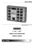
1
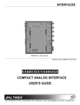
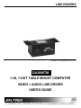
LINE DRIVERS
MANUAL PART NUMBER: 400-0174-001
DA2000TM
1-IN, 1-OUT TABLE MOUNT COMPUTER
VIDEO + AUDIO LINE DRIVER
USER’S GUIDE
LINE DRIVERS
TABLE OF CONTENTS
Page
PRECAUTIONS / SAFETY WARNINGS .............. 2
GENERAL ......................................................... 2
INSTALLATION................................................. 2
CLEANING ........................................................ 2
FCC / CE NOTICE............................................. 2
ABOUT YOUR DA2000TM ................................... 3
TECHNICAL SPECIFICATION ............................. 3
PRODUCT DESCRIPTION................................... 4
VIDEO INPUT ................................................... 5
VIDEO OUTPUT ............................................... 5
AUDIO INPUT & OUTPUT ................................ 5
POWER INPUT CONNECTOR ......................... 5
POWER/SIGNAL PRESENT INDICATOR ........ 5
APPLICATION DIAGRAM .................................... 6
INSTALLING YOUR DA2000TM........................... 6
OPERATION ........................................................ 6
ACCESSORIES.................................................... 7
FREQUENTLY ASKED QUESTIONS................... 7
TROUBLESHOOTING GUIDE ............................. 8
ALTINEX POLICY................................................. 8
LIMITED WARRANTY....................................... 8
RETURN POLICY ............................................. 8
CONTACT INFORMATION ............................... 8
1
LINE DRIVERS
PRECAUTIONS / SAFETY WARNINGS
1.4 FCC / CE NOTICE
1
Please read this manual carefully before using your
DA2000TM. Keep this manual handy for future
reference. These safety instructions are to ensure
the long life of your DA2000TM and to prevent fire
and shock hazard. Please read them carefully and
heed all warnings.
•
1.1 GENERAL
•
•
•
Unauthorized personnel shall not open the unit
since there are high-voltage components
inside.
Qualified ALTINEX service personnel, or their
authorized representatives must perform all
service.
1.2 INSTALLATION
•
•
•
•
For best results, place the on a flat, level
surface in a dry area away from dust and
moisture.
To prevent fire or shock, do not expose this
unit to rain or moisture. Do not place the
DA2000TM in direct sunlight, near heaters or
heat radiating appliances, or near any liquid.
Exposure to direct sunlight, smoke, or steam
can harm internal components.
Handle the DA2000TM carefully. Dropping or
jarring can damage internal components.
•
Never install the DA2000TM in the same
enclosure with high voltage wires or their
associated components, such as power
sockets, dimmers or switches. Always use
proper isolation techniques to ensure that the
DA2000TM is never installed in an enclosure
that has high voltages within it.
1.3 CLEANING
•
Clean surfaces with a dry cloth. Never use
strong detergents or solvents, such as alcohol
or thinner. Do not use a wet cloth or water to
clean the unit.
2
This device complies with part 15 of the FCC
Rules. Operation is subject to the following two
conditions: (1) This device may not cause
harmful interference, and (2) this device must
accept any interference received, including
interference that may cause undesired
operation.
This equipment has been tested and found to
comply with the limits for a Class A digital
device, pursuant to Part 15 of the FCC Rules.
These limits are designed to provide
reasonable
protection
against
harmful
interference when the equipment is operated
in a commercial environment. This equipment
generates, uses, and can radiate radio
frequency energy and, if not installed and used
in accordance with the instruction manual, may
cause
harmful
interference
to
radio
communications. Operation of this equipment
in a residential area is likely to cause harmful
interference in which case the user will be
required to correct the interference at his own
expense.
Any changes or modifications to the unit not
expressly approved by ALTINEX, Inc. could
void the user’s authority to operate the
equipment.
LINE DRIVERS
ABOUT YOUR DA2000TM
Ship Weight (pounds)
1.6 lb. (.73kg)
Material
Steel
Finish
Black Zinc
Front Panel
White or Ivory
T° Operating
10°C -35°C
T° Maximum
50°C
Humidity
90% non-condensing
MTBF (calculations)
40,000 hrs.
Table 2. DA2000TM Mechanical
2
The DA2000TM is a computer video + stereo audio
line driver designed for mounting under a table or
to other surfaces in tight spots. Its extremely
compact form promotes inconspicuous attachment,
yet still allows for active components necessary to
drive high-resolution computer signals a distance of
up to 100 feet or more.
The DA2000TM offers a female VGA-type 15-pin
HD input connector and a stereo audio mini jack on
its front panel. The rear panel offers three terminal
block connectors for the connection of RGBHV,
balanced stereo audio and low voltage power (9V
DC). This unit is compatible with VGA, SVGA,
XGA, SXGA, UXGA, and QXGA signal formats.
ELECTRICAL
Input Video Signal
Level
Impedance
Input Sync Signals
Horizontal & Vertical
Impedance
Output Video Signals
Level
Impedance
The DA2000TM provides fully buffered, amplified
outputs. Also, the DA2000TM converts an incoming
unbalanced stereo audio signal to balanced stereo
audio on the output.
Equalization
ALTINEX offers optional adhesive A/V label sheets,
allowing the inputs to be labeled as needed. All
accessories, including the power adapter and the
input cable, must be ordered separately.
TECHNICAL SPECIFICATIONS
1.7V max
75 ± 1% (terminated)
TTL (+/-)
10k Ohms
1.7V p-p max (terminated)
75Ohms
Optimized for 75ft of high
resolution coax
Output Sync Signals
Composite,
TTL (+/-)
Horizontal, & Vertical
Impedance
22Ohms
Frequency Compatibility
Horizontal
15-130kHz
Vertical
25-180Hz
Minimum Video
-3dB @ 350MHz
Bandwidth
Cross talk
-20dB @ 100MHz
Audio Input
Impedance
10k
Max Level
0dBu
Audio Throughput
Gain
+6dB balanced, 0dB
unbalanced
Frequency Response 10Hz to 20kHz (+/- 0.05 dB)
Noise Floor
-98dB @ 20kHz
CMRR
<40dB, 10Hz to 20kHz
Audio Output
Impedance
50 unbalanced,100 balanced
Drive
>10dBu
Power
External Power
9VDC 500mA supply
Table 3. DA2000TM Electrical
3
FEATURES/DESCRIPTION
DA2000TM
GENERAL
Inputs
Computer Video Input
15-pin HD Female
Connector
Audio Input Connector
3.5mm stereo audio
Outputs
Video Output Connector
10-pin terminal block
Audio Output Connector
5-pin terminal block
Power
9VDC 500mA supply
2-pin terminal block
Compatibility
VGA/SVGA/XGA/UXGA MAC/SUN/SGI and other
analog computer video sources
Table 1. DA2000TM General
MECHANICAL
Depth (inches)
Width (inches)
Height (inches)
Weight (pounds)
DA2000TM
DA2000TM
4.1 in. (105mm)
1.5 in (39mm)
2.1 in. (54mm)
1 lb. (.45kg)
3
LINE DRIVERS
PRODUCT DESCRIPTION
4
4
LINE DRIVERS
PRODUCT DESCRIPTION (CON’T)
PIN No.
OUTPUT SIGNAL ON 10-PIN
MALE TERMINAL BLOCK
VERTICAL
9
SIGNAL RETURN
10
Table 5. 10-pin Male terminal block for video output
4.1 VIDEO INPUT
The VGA computer input 15-pin HD connector on
the front of the DA2000TM is connected to the
video output of a desktop computer. The
DA2000TM may be used with a six foot Male to
Male VGA input cable (ALTINEX part #
CB3706MR) and a six foot audio cable (ALTINEX
part # CB1206AU).
4.3 AUDIO INPUT & OUTPUT
The DA2000TM accepts computer audio input and
offers balanced stereo output through a terminal
block connector on the back panel. There is a
3.5mm jack for computer audio input, which may
be returned to an amplifier. A 5-pin terminal block
is available for stereo audio transmission to the
main sound system. These connectors are easily
adaptable to stereo mini or RCA type connectors.
PIN No.
Input signals on 15-pin HD
female connector
RED
1
GREEN
2
BLUE
3
ID2
4
SCL/SDA
REF
5
SIGNAL RETURN
6
SIGNAL RETURN
7
SIGNAL RETURN
8
VESA POWER INPUT
9
SIGNAL RETURN
10
IDØ
11
SDA
12
HORIZONTAL
13
VERTICAL
14
SCL
15
Table 4. The DA2000TM’s input pin-outs
PIN No.
OUTPUT SIGNAL ON 5-PIN
MALE TERMINAL BLOCK
L+IN (Left Channel)
1
L-IN (Left Channel)
2
SIGNAL RETURN
3
R+IN (RIGHT Channel)
4
R-IN (RIGHT Channel)
5
Table 6. 5-pin Male terminal block for audio output
4.4 POWER INPUT CONNECTOR
The DA2000TM has a 2.5mm DC power jack for
connection to a 9V 500mA power external
adapter. The power regulation is provided inside
the unit. A selection of several power adapters is
available for different countries from 110 VAC to
240 VAC.
4.2 VIDEO OUTPUT
The DA2000TM offers a buffered video output
through a 10-pin terminal block on the back of the
unit. The DA2000TM Line Driver allows a
connection to different types of projectors or
monitors using ALTINEX cables.
PIN No.
1
2
3
4
5
6
7
8
4.5 POWER/SIGNAL PRESENT INDICATOR
The DA2000TM has an LED on the front panel,
which provides feedback to the user. When power
is connected to the DA2000TM, the LED will turn
red. When a computer video source is connected
to the DA2000TM, the LED will turn green,
indicating that the unit is receiving a signal by
sensing the presence of the sync portion of the
signal.
OUTPUT SIGNAL ON 10-PIN
MALE TERMINAL BLOCK
RED
GROUND
GREEN
GROUND
BLUE
GROUND
HORIZONTAL
GROUND
5
LINE DRIVERS
APPLICATION DIAGRAM
5
Note that the coaxial cable’s braided shield is
twisted into a single conductor with multiple
strands. There is approximately ¼ inch of the
center conductor exposed, and ½ inch of the center
conductor shield exposed.
INSTALLING YOUR DA2000TM
OPERATION
6
7
The DA2000TM will operate successfully as long
as all cables are attached properly and other
technical specifications are followed.
Step 1. Mount the DA2000TM to the underside of
a table and apply 9VDC power to the unit.
The LED should turn red, indicating power
but no incoming video signal.
Step 2. Connect an active video source to the
front of the DA2000TM. The LED should
turn green.
If the DA2000TM is
connected to a display, you should see an
image.
Step 3. Connect an active audio source to the
front of the DA2000TM. If the DA2000TM
is connected to an audio amplifier with
speakers, you should hear sound.
6
LINE DRIVERS
ACCESSORIES
8
FREQUENTLY ASKED QUESTIONS
Model No.
INPUT
CABLES
Description
STANDARD 15-PIN VGA MALE TO
MALE (COAXIAL TYPE CABLE
INTERNALLY)
3 ft
CB3703MR
6 ft
CB3706MR
15 ft
CB3715MR
25 ft
CB3725MR
3.5mm cable for audio
CB1206AU
STANDARD 15-PIN VGA MALE TO FEMALE
(COAXIAL TYPE CABLE INTERNALLY)
3 ft
CB3903HR
6 ft
CB3906HR
15 ft
CB3915HR
25 ft
CB3925HR
HIGH RESOLUTION MULTI-CHANNEL COAX
3 ft
CB4203MR
6 ft
CB4206MR
12 ft
CB4212MR
25 ft
CB4225MR
50 ft
CB4250MR
75 ft
CB4275MR
CB42100MR 100 ft
CB42150MR 150 ft
POWER SUPPLIES
9V 500mA Power Supply for US
PS5502US
9V 500mA Power Supply for UK
PS5512UK
9V 500mA Power Supply for Australia
PS5522AU
9V 500mA Power Supply for Germany
PS5532GR
9V 500mA Power Supply for Japan
PS5542JP
No:
1
2
3
4
7
Question
How many
feet of cable
can I use with
the
DA2000TM?
Is the input
cable type
important
when I use
the
DA2000TM?
9
Answer
The DA2000TM is optimized
for 75ft, but longer or shorter
lengths may be used.
The DA2000TM
may be used with two types
of input cables — VGA Ytype cables and straight
VGA Male to Male cables.
We recommend straight
input VGA cables for best
results.
What are the The resolutions of input
resolutions of computer signals that can
input
pass through the DA2000TM
computer
are as follows: a) 1280x1024
signals that
– UXGA
can pass
b) 1024x768 – XGA
through the
c) 800x600 – SVGA
DA2000TM? d) 640x480 – VGA
May I use cat No, you can not use cat 5
5 cable
cable instead of coaxial
instead of
cable because the quality of
coaxial
the received signal will be
cable?
lost.
LINE DRIVERS
TROUBLESHOOTING GUIDE
11.2 RETURN POLICY
10
It is very important to ALTINEX that you receive
the products that you have ordered and that this
product meets your expectations. In the unlikely
event, that an ALTINEX product needs to be
returned please follow the policy below:
We have carefully tested and have found no
problems in the supplied DA2000TM unit; however,
we would like to offer the following suggestions:
•
Make sure that the display equipment is
compatible with the source equipment.
•
Please make sure that input amplitude of the
video analog signal is less than 1.5V and is at
TTL level for SYNC signal.
•
Please use the ALTINEX provided external AC
adapter, which supplies 9V DC at 500mA.
•
Please make sure that the proper quality of
cables with coaxial component for video and
audio channels is used. We recommend
ALTINEX made cables for best results.
•
ALTINEX will accept product returns for a period
of 30 days from authorized ALTINEX dealers.
Products must be returned in an unopened
package.
If a product has been opened, the restocking fees
will apply. For the restocking fee amount, please
contact an ALTINEX Sales Representative.
If the product is in your possession for more than
30 days the restocking, fees will apply.
ALTINEX will not accept any returns on cables or
custom products.
If a problem arises after continuous usage at
higher voltage, higher temperature, higher
humidity, or at other extreme environmental
conditions, please correct the problem.
ALTINEX POLICY
If your product is in warranty and needs service,
contact the ALTINEX Sales Department for an
RMA (Return Material Authorization). Products
returned without an RMA number may experience
a delay in service.
11
If your product is out of warranty and needs
service, contact the ALTINEX Sales Department
for an RMA (Return Material Authorization).
Products returned without an RMA number may
experience a delay in service. The service
charges will be quoted to you before the actual
repairs are done.
11.1 LIMITED WARRANTY
ALTINEX warrants that its products and cables
are free from defects in materials under normal
use and service. This warranty is limited to
repairing at company’s factory any part or parts of
the product, which upon company’s examination
shall disclose to be, thus defective. Products
considered defective should be returned to
company with transportation charges pre-paid
within 2 years or (90 days for cables) from date of
shipment to the purchaser. The warranty is
expressly instead of all other warranties
expressed or implied. ALTINEX neither assumes
nor authorizes any other person to assume for it
any other liability in connection with the sale of the
products. This warranty shall not apply to any
product that shall have been repaired or altered
outside of company’s factory in any way so as, in
its judgment, to affect its stability or reliability, or
that has been subject to misuse, negligence or
accident.
11.3 CONTACT INFORMATION
ALTINEX, INC.
592 Apollo Street
Brea, CA 92821 USA
TEL: 714-990-2300
TOLL FREE: 1-800-ALTINEX
WEB: www.altinex.com
E-MAIL: [email protected]
FAX: 714-990-3303
8