1
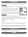
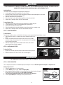
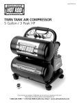
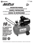
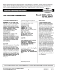
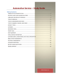
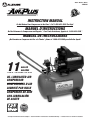
Model / Modéle / Modelo
#540010
INSTRUCTION MANUAL
Do Not Return Your Compressor to the Store! Call 1-800-423-3598 For Help!
MANUEL D'INSTRUCTIONS
Ne Pas Retourner le Compresseur au Magasin ! Pour Toute Assistance, Appeler le 1-800-423-3598 !
MANUAL DE INSTRUCCIONES
¡No Deveulva su Compresor de Aire a la Tienda! ¡Llame al 1-800-423-3598 para Solicitar Ayuda!
11
GALLON
GALONES
3.5 PEAK HP * / 3.5HP * EN POINTE / 3.5HP * DE PICO
OIL LUBRICATED AIR
COMPRESSOR
COMPRESSEUR D'AIR
LUBRIFIÉ PAR HUILE
COMPRESOR DE AIRE
CON LUBRICACIÓN
DE ACEITE
4.7/3.0
* Based Upon Peak Electrical Current Consumption • * Puissance Déterminée en Fonction de la Consommation Électrique • * Calculado en Base a la Corriente Pico Consumida
Instruction Manual
It is the owner and/or operator's responsibility to study all WARNINGS, operating, and maintenance instructions contained on the product label and instruction manual prior to operation of this unit. The owner/operator shall retain product instructions for future reference.
The owner and/or operator is responsible for maintenance, maintaining all decals or warning labels and while in use, maintaining the
unit in good working order. If the owner and/or operator is not fluent in English, Spanish, or French, the product warnings and instructions shall be read and discussed with the operator's native language by the purchaser/owner or his designee. Make sure that the operator comprehends its contents. Safety information shall be emphasized and understood prior to usage. The air compressor shall be
inspected per the operating instructions.
Users of this air compressor must fully understand these instructions. Each person operating this air compressor must also be of
sound mind and body and must not be under the influence of any substance that might impair their vision, dexterity, or judgment.
Protect yourself and others by observing all safety information.
Failure to comply with instructions could result in personal injury and/or property damage!
If you encounter any problems or difficulties, please contact our customer service department at:
1-800-423-3598
1-310-522-9008
1-310-522-9066 Fax
INTRODUCTION
This oil lubricated air compressor is designed for household use only and is not intended for commercial applictions. It is well suited
for do-it-yourselfers with a variety of home and automotive uses.
This instruction manual is intended for your benefit. Please read and follow the safety, installation, maintenance and troubleshooting
steps described within to ensure your safety and satisfaction. The contents of this instruction manual are based upon the latest product
information available at the time of publication. The manufacturer reserves the right to make product changes at any time without
notice.
SAFETY ALERT
WARNING
READ AND UNDERSTAND THIS ENTIRE INSTRUCTION MANUAL BEFORE ATTEMPTING TO ASSEMBLE, INSTALL, OPERATE OR MAINTAIN THIS AIR COMPRESSOR. FAILURE TO COMPLY WITH THE INSTRUCTIONS MAY RESULT IN SERIOUS PERSONAL INJURY
AND/OR PROPERTY DAMAGE!
2
THE FOLLOWING SIGNAL WORDS ARE USED TO EMPHASIZE SAFETY WARNINGS THAT MUST BE FOLLOWED WHEN USING THIS
AIR COMPRESSOR:
DANGER
Indicates an imminently hazardous situation that, if not avoided, WILL result in death or serious injury.
WARNING
Indicates a potentially hazardous situation that, if not avoided, COULD result in death or serious injury.
CAUTION
Indicates a potentially hazardous situation that, if not avoided, MAY result in minor or moderate injury.
NOTICE
Indicates important information, which if not followed, MAY cause damage to equipment.
UNPACKING & INSPECTION
After opening the carton, unpack your new air compressor and related parts & accessories. Please inspect it carefully for any damage
that may have occurred during transit. Please check it against the photograph on carton. If any parts are missing, please call factory
customer service at 1-800-423-3598.
WARNING
DO NOT OPERATE THIS AIR COMPRESSOR IF DAMAGED DURING SHIPMENT, HANDLING OR MISUSE. DAMAGE MAY RESULT IN
BURSTING, WHICH CAN CAUSE SERIOUS INJURY OR PROPERTY DAMAGE.
All damaged parts must be repaired or replaced as needed prior to operating this air compressor.
Check to see that all nuts, bolts and fittings are secure before putting this air compressor into service. If you have any questions, or
require assistance with damaged or missing parts, please contact our factory customer service department at:
1-800-423-3598
1-310-522-9008
1-310-522-9066 Fax
Please have the serial number, model number, date of purchase, and parts list, (with missing parts identified), available for reference
when calling.
MODEL NUMBER:
540010
SERIAL NUMBER:
DATE OF PURCHASE:
SAFETY WARNINGS
READ ALL SAFETY WARNINGS BEFORE USING AIR COMPRESSOR
General Safety Warnings:
Keep work area clean. Messy areas and cluttered workbenches invite personal injury, and/or property damage.
Keep children and visitors away. All children should be kept away from the work area. DO NOT let children handle the compressor or
extension cord. Maintain a safe distance for any person near the work area.
Operating any tools or equipment under the influence of drugs, alcohol, or medication can cause personal injury to yourself and others.
Wear proper apparel. Remove your jewelry before using air compressor. Do not wear loose clothing, necklaces, rings, bracelets, or
other jewelry, which may get caught in moving parts. Nonskid footwear and electrically conductive gloves are highly suggested while
working. Wear protective hair covering to contain long hair.
3
Protect your eyes. The operation of any air compressor can result in foreign objects being thrown into the eyes, which can result in
severe eye damage. Always wear eye protection that meets ANSI Z28.1 specifications during air compressor operation. Eyeglasses are
not always safety glasses.
Be responsible for your hearing. Wear hearing protection during extended periods of operation.
Use the right tool. Use tools properly and for their intended task. Do not force a small tool to do the job of a heavy-duty tool. Using the
right tool to do the right job will do the job intended safer.
Check damaged parts before use of any air tools or attachments, a guard or other part that is damage should be carefully checked to
ensure that it would operate properly and perform its intended function. Check for misalignment or binding of moving parts, breakage
of parts, mounting, or any other conditions that may affect tool operation. A guard or other part that is damage should be properly
replaced. See replacement parts list for additional details.
Avoid unintentional starting. Be sure that your air compressor is in the off position before plugging it into a power cord or electrical
receptacle.
Store all maintenance tools away from the immediate area before turning “on” your air compressor.
Do not overreach. Proper footing and balance is a must at all times while using tools. Unstable support may lead to personal injury. Do
not stand on the tool. Serious injury could result if the tool tips over or you accidentally contact tool.
Never leave the air compressor running unattended. Always turn the power to the “off” position and do not leave the air compressor
until it come to a complete stop.
When using air accessories consult the owner's manual provided by the manufacturer. The use of improper accessories may cause risk
of injury to yourself and others.
Always make sure the tool is in the “off” position and unplugged from the electrical receptacle when making adjustments, changing
parts or performing any maintenance.
Secure work. When possible, the use of clamps or holding device is much safer than holding the work piece with your hands.
Keep protective guards in place and in proper working condition.
Maintain tools and equipment with care. They will function better and safer when kept clean and in good working condition. Keeping the
air compressor clean, dry, and free of grime will add to its life and performance.
Childproof the workshop. The use of master switches and padlocks is highly recommended. Remove starter keys where applicable.
WARNING
Some dust created by spraying, blowing, power sanding, sawing, grinding, drilling and other construction activities contains chemicals
known to the State of California to cause cancer, birth defects or other reproductive harm.
Reduce your exposure to these chemicals by wearing approved safety equipment such as dust masks that are designed to filter out
microscopic particles.
WARNING
Use of this product will expose you to chemicals known to the State of California to cause cancer, birth defects, and reproductive harm.
Avoid inhaling vapors and dust. Wash hands after using.
WARNING
This product contains chemicals, including lead, known to the State of California to cause cancer, birth defects, and reproductive harm.
Wash hands after handling.
4
WARNING
DRAIN LIQUID FROM AIR TANK DAILY - Use the drain valve located on the bottom of the air tank to drain. Failure to properly drain liquid from the tank will cause rust from moisture buildup, which weakens the tank and could lead to a violent tank explosion. Periodically
inspect the tanks for unsafe conditions such as corrosion, cracked welds, and leaks.
Release air slowly when draining moisture or depressurizing the air compressor. Fast moving air will stir up dust, dirt and debris that
may be harmful.
WARNING
RISK OF FIRE OR EXPLOSION - Avoid dangerous environments. Do not spray combustible/flammable liquid in a confined area. Spray
area must be well ventilated. Do not smoke while spraying or spray where spark or flame is present. Arcing parts - keep compressor at
least 20' away from spraying area and all explosive vapors. Do not use compressor near gasoline or other flammable materials. Operate
the air compressor in a well-ventilated area. Do not direct paint or other spray material towards the compressor. Read and follow all
safety instructions for the material you are spraying. Be sure to use an approved respirator designed for use with your specific application.
WARNING
RISK OF INJURY - Do not direct air stream at body. Use eye protection. Compressor starts automatically. Do not touch MOVING
PARTS. Keep guards in place. Compressor does not supply breathable air.
DANGER
RISK OF BURSTING - Do not adjust regulator to result in output pressure greater than marked maximum pressure of attachment. If a
regulator has not been installed, use only attachment rated at 200 PSI or higher. Do not weld on or repair tank - A DAMAGED TANK
MUST BE REPLACED IMMEDIATELY. Do not operate without proper safety valve in place.
Never attempt to repair or make modifications to the tank or its attachments. Welding, drilling or any other modifications may weaken
the tank, which may result in damage from rupture or explosion. Never remove or attempt to adjust the pressure switch, safety valve, or
other components that control tank pressure. Never substitute parts or attempt to alter the factory set operating pressures.
DANGER
RISK OF ELECTRICAL SHOCK - Disconnect AIR COMPRESSOR from power source before servicing. USE PROPERLY grounded ELECTRICAL CONNECTIONS - Do not use grounding adaptors. Do not use in wet or damp locations or expose to rain. Keep all connections
dry and off the ground. Do not allow power cords to come into contact with water. Do not touch the plug with wet hands. Do not pull
on the electrical cord to disconnect from the power outlet. Store air compressor indoors when not in use. Any electrical wiring or
repairs performed on this air compressor should be done by authorized service personal in accordance with national and local electrical
codes.
WARNING
RISK TO BREATHING - This air compressor is not designed, nor intended for the supply of breathable quality air. Air produced by this
unit may contain carbon monoxide or other toxic vapors. Do not inhale air from the compressor or from a breathing device connected
to it.
Operate the air compressor in a well-ventilated area. Read and follow all safety instructions for the material you are spraying. Be sure to
use an approved respirator designed for use with your specific application.
CAUTION
RISK OF BURNS - Keep hands and fingers away from exposed metal parts on a running air compressor. Air compressors generate significant heat during normal operation, which can cause serious burns. The compressor will remain hot for some time after operation
and should not be touched or moved until cool.
5
WARNING
RISK OF FLYING OBJECTS - Do not direct compressed air stream at people or pets. The powerful compressed air stream can damage
exposed skin and easily propel loose dirt and other small objects at high-speed, resulting in serious injury. Always wear eye protection
that meets ANSI Z28.1 specifications. Use only OSHA approved air blowguns. Never leave a pressurized air compressor unattended.
Shut off air compressor and relieve pressure before performing maintenance or repairs. Do not move the air compressor while the air
tank is pressurized. Never attempt to move the air compressor by pulling on the air hose.
WARNING
RISK OF FALLING - Portable air compressors can fall from a table, workbench or roof causing damage to the compressor and could
result in serious injury or death to the operator. Always operate air compressor in a stable and secure position to prevent accidental
movement of the unit. Never operate air compressor on a roof or other elevated position. Use additional air hose to reach high locations.
WARNING
RISK OF PROPERTY DAMAGE WHEN TRANSPORTING COMPRESSOR - Oil can leak or spill and could result in fire or breathing hazard,
serious injury or death can result. Oil leaks will damage carpet, paint, or other surfaces in vehicles or trailers.
WARNING
AIR TOOLS AND ACCESSORIES - Do not exceed the pressure rating of any air tools, spray guns, air accessories, or inflatables. Excess
pressure can cause them to explode, resulting in serious injury. Follow the manufacturers recommended pressure settings for all air
tools and air accessories.
SPECIFICATIONS
•
•
•
•
•
•
•
•
•
•
•
•
3.5 Peak HP
11 Gallon Air Tank
Oil Lubricated Direct Drive Pump
Cast-iron Cylinder
Maximum Pressure: 125 PSI
Power: 115V, 60 Hz, 15 Amps
Air Delivery: 4.7 SCFM output @ 40 PSI / 3.0 SCFM output @ 90 PSI
Duty Cycle: 50%
Thermal Overload Protection for Safety
High Flow Regulator for Precision Air Flow Control
Dual Pressure Gauges
Weight: 84 lbs. (38 kg)
Duty Cycle:
Duty cycle refers to the percentage of time a compressor can safely run within a given amount of time expressed as a ratio. Oil lubricated compressors are typically rated at a 50% duty cycle, meaning that the compressor motor can run about 50% of the total time it is
being used to supply air to a tool. During the “on” time, the motor is running to pressurize the tank. During the “off” time, the motor is
stopped and the tools are running off on the pressurized air stored in the tank. If your air tools are draining pressure off of the tank too
quickly, the compressor motor must run more than 50% of the time the compressor is in use. This can lead to overheating and will significantly shorten the life of the compressor.
INSTALLATION AND LOCATION
The compressor must be used on a stable level surface. The air compressor must be used in a clean and well-ventilated area. The compressor requires an unobstructed airflow and must be located a minimum of 20 inches from any walls or other obstructions.
6
GROUNDING INSTRUCTIONS
This product should be grounded. In the event of an electrical short circuit, grounding reduces the risk of electric shock by providing an
escape wire for the electric current. This product is equipped with a cord having a grounding wire with an appropriate grounding plug.
The plug must be plugged into an outlet that is properly installed and grounded in accordance with all local codes and ordinances.
DANGER
Improper installation of the grounding plug can result in a risk of electric shock. If repair or replacement of the cord is necessary, do
not connect the grounding wire to either flat blade terminal. The wire with insulation having an outer surface that is green with or without yellow stripes is the grounding wire.
Figure 1
This product is for use on a nominal 120-volt circuit and has a three-prong grounding plug that
looks like the plug illustrated in Figure 1. Make sure that the product is connected to an outlet
having the same configuration as the plug. No adapter could be used with this product.
Grounded Outlet Box
Grounded Outlet
The use of a GFCI outlet is strongly recommended. The third prong is to be used to ground the
tool and provide protection against electrical shock. Never remove the third prong.
Check with a qualified electrician or serviceman if the grounding instructions are not completely
understood, or if in doubt as to whether the product is properly grounded. Do not modify the plug
provided; if it will not fit the outlet, have the proper outlet installed by a qualified electrician.
115 Volts
15 AMP
Plug
Grounding Plug
CAUTION
Extension Cords - Alltrade does not recommend the use on an extension cord with this product as this may result in the loss of power
and overheating of the motor. An additional air hose should be used instead of an extension cord.
However, if the use of an extension cord is unavoidable, use only UL listed three wire extension cords that have three-pronged grounding type plugs and three prong receptacles that accept the tool's plug. Improper use of extension cords may cause inefficient operation
of your tool, which can result in overheating. Be sure your extension cord is rated to allow sufficient flow to motor. Refer to the guide
below for minimum gauge required for extension cords.
Extension Cord Length
Up to 25 Feet
26 to 50 Feet
51 to 100 Feet
Wire Size (A.W.C.)
14
12
10
Use of an extension cord rated to carry the current the tool will draw is very important, especially when the power source is at great
distance. An extension cord of insufficient rating will cause a drop in line voltage, resulting in power loss and causing the motor to
overheat.
Guard against electrical shock. Avoid body contact with grounded services such as pipes, radiators, ovens, stoves, and refrigerator
enclosures. If not properly grounded, this power tool can incur the potential hazard of light trickle shock, particularly when used in
damp locations. If an electrical shock occurs, there is the potential of a secondary hazard such as your hands contacting an operating
air tool.
COMPRESSOR FEATURES
1. Oil Lubrication: Oil lubricated direct drive pump with cast-iron cylinder for durability.
2. OIL FILL SIGHT GLASS: Located on the face of the crankcase, the oil fill sight glass provides a convenient way to check the oil fill
level within the pump. The oil level must be checked prior to each use to ensure proper fill level.
WARNING
DO NOT OPERATE THE COMPRESSOR WITHOUT LUBRICANT, OR WITH LOW LUBRICATION LEVEL. ALLTRADE IS NOT RESPONSIBLE
FOR DAMAGE CAUSED TO THE COMPRESSOR DUE TO OPERATION WITHOUT PROPER LUBRICATION.
7
3. AUTOMATIC ON/OFF PRESSURE SWITCH: This compressor is equipped with an automatic on/off pressure switch. The compressor
will only run when the switch is in the “I” (ON) position. Once the tank has reached the desired preset pressure (“cut-out” pressure), the pump motor will automatically shut off. While the switch is in the “I” (ON) position, the pump motor will automatically
turn back on once the pressure in the tank drops below the minimum preset pressure (“cut-in” pressure).
WARNING
DO NOT LEAVE THE COMPRESSOR UNATTENDED WHILE THE POWER SWITCH IS IN THE “I” (ON) POSITION.
4. AIR TANK PRESSURE GAUGE: The tank pressure gauge provides a reading of the air pressure inside of the compressor tank.
5. PRESSURE REGULATOR: The regulator allows you to select the amount of air pressure that is output through the air hose into
tools and accessories. Turn the pressure regulator knob clockwise to increase discharge pressure, and counter clockwise to
decrease discharge pressure. Please refer to the air delivery requirements of your tools for the proper pressure settings. NOTICE:
Be careful not to over tighten pressure regulator knob when it “bottoms out” as this may damage pressure regulator.
6. OUTLET PRESSURE GAUGE: The outlet pressure gauge provides a reading of the air pressure at the outlet side of the regulator.
This pressure is controlled by the pressure regulator and is always less than or equal to the air tank pressure.
7. AIR OUTLET PORT: The air outlet port is located on the pressure regulator body. This port is threaded to accommodate standard
1/4" NPT (M) air fittings found on air hoses and quick connectors. Use PTFE thread-sealing tape on the threads to make sure you
have an airtight connection.
8. SAFETY RELIEF VALVE: This compressor is equipped with a safety relief valve that is designed to prevent system failures by relieving pressure from the system when the air pressure reaches a predetermined level. The safety relieve valve is preset by the manufacturer - DO NOT attempt to modify or remove the safety relief valve.
9. AIR TANK DRAIN VALVE: Moisture is produced whenever air is compressed. It is critical to drain water from the air tank on this
compressor frequently. If unit is used only occasionally, tank should be drained after each use and prior to the next use. To drain
the tank, slowly open the tank drain fitting by turning clockwise. Once all moisture has drained out, close the fitting securely. NOTE:
Air tank will not pressurize while drain valve is open.
10. AIR INTAKE FILTER: This compressor is equipped with an externally accessible air intake filter that is designed to clean air coming
into the pump. The filter element is easily removed for periodic cleaning with warm soapy water. Rinse the filter and air dry before
reinstalling. Replace filter element when necessary. NOTICE: Remove air inlet dust plug and install air filter as indicated in
assembly instructions before using air compressor.
11. THERMAL SHUTDOWN SWITCH: The electric motor is equipped with an automatic thermal overload protector. If the unit is overheating, the motor will automatically shut down. Turn the unit off and allow the unit to cool for approximately 20 minutes before
turning the unit back to the “I” (ON) position. NOTICE: This air compressor is designed for household use only and is not intended
to operate heavy-duty air tools. If your application's demands exceed the capacity of this air compressor, a larger air compressor
that is matched to your application is recommended. If the unit shuts down again, please call factory customer service at 1-800423-3598 for assistance.
12. HANDLE: Convenient handle for easy transport.
13. WHEELS: Large diameter wheels for easy mobility.
ASSEMBLY INSTRUCTIONS
STEP 1 - INSTALLING WHEELS AND RUBBER FEET
WARNING
THE WHEELS AND HANDLE DO NOT PROVIDE ADEQUATE CLEARANCE, STABILITY OR SUPPORT FOR PULLING THE UNIT UP AND
DOWN STAIRS OR STEPS. THE UNIT MUST BE LIFTED, OR PUSHED UP A RAMP.
8
CAUTION
IT MAY BE NECESSARY TO BRACE OR SUPPORT ONE END OF THE AIR COMPRESSOR WHEN ATTACHING THE WHEELS AND THE
RUBBER FEET, BECAUSE THE AIR COMPRESSOR WILL HAVE A TENDENCY TO TIP.
Installing Wheels:
The wheels must be installed prior to operating the compressor.
1. Insert supplied wheel bolt through hole in center of wheel.
2. Place the end of the bolt on the wheel subassembly through the corresponding hole in the wheel
ground iron located on the base of the air tank.
3. Slide lock washer over end of wheel bolt.
4. Fasten the wheel in place by threading supplied nut onto the wheel bolt.
5. Repeat steps 1 through 4 above to install second wheel.
To Install Rubber Feet:
1. Slide washer over screw and insert into cup shaped end of rubber foot pad.
2. Insert exposed end of bolt into corresponding hole in ground iron.
3. Place washer over the end of the screw.
4. Fasten the rubber foot in place by threading nut onto the end of the mounting screw.
5. Repeat steps 1 through 4 above to install second rubber foot pad.
STEP 2 - INSTALLING HANDLE
To Install Handle:
The horizontal handle receivers are installed at the factory and are permanently attached to the air tank.
1. Slide foam grip so that it is centered over end of horizontal handle crosspiece.
2. Position the horizontal handle crosspiece over the tops of the handle
receivers, lining up the openings in the crosspiece pipe with the openings
of the handle receiver tubes.
3. Slide the crosspiece ends into the handle receiver tubes and secure in
place using the four (4) bolts supplied.
STEP 3 - INSTALLING AIR FILTER
To Install Air Filter:
1. Remove air inlet dust plug from pump cylinder head using long nose pliers.
2. Insert threaded end of air filter into air inlet and hand tighten.
WARNING
THE COMPRESSOR IS SHIPPED WITHOUT OIL IN THE CRANKCASE. ADD OIL AS INDICATED BELOW.
STEP 4 - PUMP LUBRICATION
This air compressor features an oil lubricated pump that requires the use of SAE 30 weight non-detergent air compressor oil.
Adding Compressor Oil:
1. Place air compressor on a flat, level surface.
2. Remove WHITE plastic oil plug - used for shipping ONLY.
3. Open supplied oil bottle and pour oil into crankcase until the oil level reaches the top of
the red circle in the oil level sight glass. Be careful not to overfill.
4. See diagram for determining proper oil fill level using oil fill sight glass.
5. Install supplied RED plastic oil fill plug securely into oil fill hole.
CAUTION
CHECK OIL
LEVEL DAILY!
OIL LEVEL OK
REFILL OIL
IMMEDIATELY
OIL CAPACITY: 28oz
9
(833ml)
WARNING
DO NOT OPERATE THE COMPRESSOR WITHOUT LUBRICANT, OR WITH LOW LUBRICATION LEVEL. ALLTRADE IS NOT RESPONSIBLE
FOR DAMAGE CAUSED TO THE COMPRESSOR DUE TO OPERATION WITHOUT PROPER LUBRICATION.
STEP 5 - INSPECTION CHECK
Assembly Check:
In order to complete the assembly of your new air compressor, a careful inspection should be made to ensure that all of the parts are
properly aligned and securely fastened.
1. Inspect wheels to ensure that they are properly mounted and secured to ground irons.
2. Inspect rubber feet to ensure that they are properly mounted and secured to ground iron.
3. Inspect handle crosspiece to ensure that it is fully secured.
4. Inspect air filter to ensure that it is installed and secure.
5. Check oil fill level in crankcase.
OPERATION
INITIAL SETUP / BREAK-IN PROCEDURE
CAUTION
Do not attach air hose, air tools or other air accessories to the air outlet until break-in procedure has been successfully completed.
1. Read and understand the entire instruction manual, including all safety warnings before setting up air compressor.
2. Place air compressor on a flat, level surface.
3. Check oil fill level in crankcase and add oil as needed.
4. Turn the pressure regulator knob fully clockwise to open airflow from air outlet port. NOTICE: Be careful not to over tighten pressure regulator knob when it “bottoms out” as this may damage pressure regulator.
5. Turn the power switch to the OFF position.
6. Plug power cord directly into a properly grounded power source of the correct voltage (see Grounding Instructions on page 7 of
this instruction manual).
7. Open the tank drain valve to allow air to escape preventing air pressure buildup in the air tank.
8. Turn the compressor on by moving the switch to the AUTO/ON position and run the air compressor for a period of 20 minutes to
break-in the air pump.
9. With the compressor still running, at the end of the 20-minute break-in period, close the tank drain valve. The air compressor will
build air pressure to the maximum preset pressure (“cut-out” pressure) and automatically shut off.
10. Slowly turn the tank drain valve to open airflow from drain and bleed off air from the air tank. The air compressor will automatically
restart once the pressure in the air tank drops below the minimum preset pressure (“cut-in” pressure).
11. Turn the compressor off by moving the switch to the OFF position.
12. Release pressure from the system. Drain moisture from the air tank by slowly opening the air tank drain valve by turning clockwise.
Tilt tank to remove all moisture. Once all the moisture has drained out, close the fitting securely. NOTE: Air tank will not pressurize
while drain valve is open.
13. Disconnect the power cord from the power outlet. NOTE: Make sure the power switch is in the OFF position when connecting or
disconnecting power cord from electrical outlet.
14. Attach the supplied recoil air hose to the air outlet port located on the air compressor regulator valve. Use PTFE thread-sealing tape
on the threads to make sure you have an airtight connection. Do not over tighten fittings.
15. Attach quick connect coupler to the remaining end of the recoil air hose. Again, use PTFE thread-sealing tape on the threads to
make sure you have an airtight connection.
16. Attach any remaining air accessories required by your application.
17. Your new air compressor is now ready to use.
STARTUP:
1. Before each startup, make sure the power switch is in the OFF position.
2. Place air compressor on a flat, level surface.
3. Check oil fill level in crankcase and add oil as needed.
4. Release pressure from the system. Drain moisture from the air tank by slowly opening the air tank drain valve by turning clockwise.
Once all the moisture has drained out, close the fitting securely. NOTE: Air tank will not pressurize while drain valve is open.
5. Turn the pressure regulator knob fully counterclockwise to close airflow from air outlet port.
6. Attach air hose and accessories
10
WARNING
TOO MUCH AIR PRESSURE CAUSES A HAZARDOUS RISK OF BURSTING. CHECK THE MANUFACTURER'S MAXIMUM PRESSURE
RATING FOR AIR TOOLS AND ACCESSORIES. THE REGULATOR OUTLET PRESSURE MUST NEVER EXCEED THE MAXIMUM PRESSURE RATING.
7.
Before connecting the compressor to the grounded outlet, check oil level, check for broken components and accessories, and
check for damage to the hose.
8. Plug power cord directly into a properly grounded power source of the correct voltage (see Grounding Instructions on page 7 of
this instruction manual).
9. Turn the compressor on by moving the switch to the AUTO/ON position and allow the tank pressure to build. Once the air pressure
reaches the maximum preset pressure (“cut-out” pressure) it will automatically shut off.
10. Slowly turn the pressure regulator knob clockwise to open airflow from air outlet port until desired output pressure is reached.
NOTE: The air compressor will automatically restart once the pressure in the air tank drops below the minimum preset pressure
(“cut-in” pressure).
SHUTDOWN:
NOTE: NEVER stop the air compressor by unplugging it from the power outlet as this may result in damage to the compressor.
1.
2.
3.
4.
5.
6.
7.
Turn the switch to the OFF position
Disconnect the power cord from the power outlet.
Turn the pressure regulator knob fully counterclockwise to close airflow from air outlet port. Check the outlet pressure gauge to
ensure that it reads 0 PSI.
Remove the air hose and any air accessories.
Drain moisture from the air tank by slowly opening the air tank drain valve by turning clockwise. Tilt tank to remove all moisture.
Once all the moisture has drained out, close the fitting securely.
Allow the compressor to cool down.
Wipe the air compressor clean and store it in a clean, dry, and non-freezing location.
MAINTENANCE
WARNING
DISCONNECT AIR COMPRESSOR FROM POWER SOURCE AND BLEED OFF ALL AIR PRESSURE BEFORE ATTEMPTING ANY MAINTENANCE OR REPAIR.
When performing any maintenance or service:
1. The air compressor must be turned off.
2. Disconnect compressor from the power source.
3. Open tank drain to bleed off all air pressure before attempting any maintenance or repair.
4. Allow compressor to fully cool before attempting any maintenance or repair.
Check the air compressor frequently for any visible problems and follow maintenance procedures each time the compressor is used.
NOTICE
All air compressors contain maintenance parts that require periodic replacement. These used parts, including air filters and used lubricating oil, may contain regulated substances that must be disposed of in accordance with local, state, and federal laws and regulations.
1.
2.
Turn compressor off and release pressure from the system. Drain moisture from the air tank by slowly opening the air tank drain
valve by turning clockwise. Tilt tank to remove all moisture. Once all the moisture has drained out, close the fitting securely.
Wipe the compressor clean.
Maintenance Checklist:
Daily:
Check oil level.
Drain accumulated liquid from tank.
11
Check for oil leaks.
Check for unusual noise and/or vibrations
Check that all fasteners are secure.
Check for air leaks+.
Wipe compressor clean.
Weekly:
Inspect and clean air filter.
Clean breather holes on oil fill plug.
Monthly:
Check for air leaks.
Check safety relief valve.
Six months or 200 operating hours*:
Change compressor oil. Use only SAE 30 weight non-detergent air compressor oil.
Replace oil more frequently when used in dusty operating environments.
* The pump oil must be changed after the first 20 hours of operation. Thereafter, change oil every 200 hours of operation or every six
months, whichever comes first. In harsh operating conditions, maintenance must be performed more frequently.
+ Apply a solution of soapy water around joints. Look for air bubbles around joints when compressor reaches the pressure cut-out limit
and the pump turns off.
Oil change:
Used lubricating oil, may contain regulated substances that must be disposed of in accordance with local, state, and federal laws and
regulations.
1.
2.
3.
4.
5.
4.
5.
6.
7.
The air compressor must be turned OFF.
Allow compressor to fully cool before attempting any maintenance or repair.
Place a suitable oil drain pan below oil drain plug.
Remove oil fill plug to allow air to enter crankcase.
Remove oil drain plug.
Allow oil to drain completely. Tilt air compressor towards the oil drain to assist draining.
Clean and replace oil drain plug.
Refill crankcase with SAE 30 weight non-detergent air compressor oil until the oil level reaches the top of the red circle in the oil
level sight glass. Be careful not to overfill.
Reinstall the oil fill plug.
Checking Safety Relief Valve:
WARNING
SAFETY VALVE MUST BE REPLACED IF IT CANNOT BE ACTUATED OR IT LEAKS AIR AFTER THE RING IS RELEASED.
1.
2.
3.
4.
5.
6.
The air compressor must be turned OFF.
Disconnect compressor from the power source.
Open tank drain to bleed off all air pressure before attempting any maintenance or repair.
Allow compressor to fully cool before attempting any maintenance or repair.
Grasp the wire ring on the safety valve.
Pull and release the ring a few times to ensure that the plunger moves in and out. Replace the safety valve if plunger does not
move or is difficult to move.
Checking Air Filter Element:
1. The air compressor must be turned OFF.
2. Disconnect compressor from the power source.
3. Open tank drain to bleed off all air pressure before attempting any maintenance or repair.
4. Allow compressor to fully cool before attempting any maintenance or repair.
5. Unscrew the filter, which is accessible from the rear of the air compressor, from the pump head by turning counter clockwise.
6. Remove the face of the filter body to access the filter element.
12
7.
8.
9.
Clean filter element with warm soapy water. Rinse the filter and air dry before reinstalling. Replace filter element if it cannot be
cleaned sufficiently.
Reinsert filter element into filter body and reinstall filter faceplate.
Screw the filter body into pump head by turning clockwise until the filter is hand tight. DO NOT OVERTIGHTEN.
MOISTURE IN COMPRESSED AIR
Moisture is a normal by-product of compressing air. As the moisture builds during compressor use, it can be carried though the air
hose. When using a paint spray gun or sandblasting gun, the use of a special filter to remove moisture from the air line is highly recommended. Moisture in the compressed air will cause water spots in paint jobs and cause blasting media to clog the sandblasting gun.
13
TROUBLESHOOTING GUIDE
Problem Encountered
Possible Cause
Possible Solution
The compressor does not
start or restart:
Power cord not plugged in.
Plug cord into grounded outlet.
Motor/Pressure switch in "OFF" position
Move switch to "AUTO" position.
Motor thermal overload switch has tripped.
Turn air compressor off, wait until the motor is cool,
then press motor thermal overload (red) button firmly until click is heard.
Fuse blown or circuit breaker has tripped.
Replace fuse or reset circuit breaker.
Check for proper fuse amperage.
Check for low voltage conditions.
Disconnect any other electrical appliances from circuit or operate air compressor on its own branch circuit.
Wrong gauge wire or length of extension
cord.
Check chart in instruction manual for proper gauge
wire and cord length.
Air tank pressure exceeds motor/pressure
switch "cut-in" pressure.
Motor will start automatically when air tank pressure
drops below "cut-in" pressure of motor/pressure
switch.
Pressure release valve on motor/pressure
switch has not unloaded pump head pressure.
Bleed the line by moving the switch to the "OFF"
position.
Defective motor, motor capacitor,
motor/pressure switch.
Contact Factory Customer Service at
1-800-423-3598.
Overloaded motor.
Have a certified electrician check the motor and
wiring, then proceed with his or her recommendations.
Improper lubrication.
See LUBRICATION section in instruction manual.
Low oil level.
Check oil level and fill if necessary.
Defective check valve.
Replace check valve.
Loose motor pulley or pump flywheel.
Tighten pulley and/or flywheel (where applicable).
Lack of oil in the pump crankcase.
Check oil level. If low, check for possible bearing
damage. Add correct amount of oil.
Carbon deposits on pistons or valves.
Remove cylinder head and inspect. Clean or replace
parts as needed.
Bearing, piston or connecting rod failure.
STOP THE COMPRESSOR! Contact Factory
Customer Service at 1-800-423-3598.
Worn connecting rod.
Replace with new connecting rod.
Worn piston wrist pin bushing.
Remove piston/connecting rod assembly from the
compressor and inspect for excess wear. Replace
worn parts as needed.
Worn bearings.
Replace worn bearings as needed. Note: Dirty oil can
cause accelerated wear. Change oil frequently using
recommended oil.
Noisy check valve.
Replace check valve.
The compressor motor
stalls:
Excessively noisy operation:
14
Problem Encountered
Possible Cause
Possible Solution
When in the Start/Stop
option, motor runs continuously:
Motor/Pressure switch does not shut off
Move the motor/pressure switch to the "OFF" posimotor when air compressor reaches "cut-out" tion. If the motor does not shut off, unplug the air
pressure and safety relief valve activates.
compressor. If the electrical contacts are welded
together, replace the pressure switch.
Air compressor is incorrectly sized.
Limit the air pressure to the capacity of the air compressor. Either use a smaller tool or a larger air compressor.
Poor ventilation.
Relocate the air compressor to an area with an
ample supply of cool, dry, and well-circulated air is
available.
Dirty cooling fins.
Clean the outer surfaces of the cooling fins on the
pump and motor assembly.
Air continues to leak at
motor/pressure switch
release valve after motor
stops:
Defective pilot valve, the check valve is stuck
open.
Remove, clean or replace.
Air continues to leak at
motor/pressure switch
release valve while motor
is running:
Defective motor/pressure switch.
Replace.
Check valve stuck in open position.
Replace check valve. DANGER - Do not disassemble
the check valve with tank pressurized. Open tank petcock valve to allow air to escape from tank prior to
servicing.
Air leaks from safety relief
valve:
Possible defective safety relief valve.
Operate safety relief valve manually by pulling on
ring. If it still leaks, it should be replaced.
Excessive tank pressure.
Defective motor/pressure switch. Replace.
Air leaks at pump:
Blown gaskets.
Replace blown gaskets and torque head bolts to 20
ft./lbs. CAUTION - Replace head gasket with a new
one each time the head is removed to ensure proper
sealing.
Air leaks at fittings:
Fittings are not tight enough.
Tighten fittings where air can be heard escaping.
Check fittings with soapy water solution. DO NOT
OVERTIGHTEN.
Air leaks in air tank:
Defective or rusted air tank.
Air tank must be replaced. DO NOT ATTEMPT TO
REPAIR AIR TANK!
Air blowing from inlet filter:
Damaged inlet (reed) valve.
Contact Factory Customer Service at
1-800-423-3598.
Overheating:
15
Problem Encountered
Possible Cause
Possible Solution
Insufficient pressure at air
tool or air accessory:
Pressure regulator knob is not turned to high Adjust pressure regulator knob to proper setting.
enough pressure.
Defective motor/pressure regulator switch.
Replace.
Restricted air intake filter.
Clean or replace the filter element.
Air leaks.
Check for leaks by applying soap solution to all fittings and connections. Bubbles will appear at leakage points. Tighen or replace leaking fittings or connections as needed.
Hose or hose connections are too small or
long.
Replace with larger hose or connectors.
Air compressor is not large enough for air
requirement.
Check the accessory air requirement. If it is higher
than the CFM or pressure supply of the air compressor, you need a larger air compressor.
Restricted air intake filter.
Clean or replace the filter element.
Leaking (reed) valve.
Drain air tank and measure pump up time. Compare
to specifications. If lower, remove pump head and
inspect valve plate, vlave seats, and vlave reeds.
Clean or replace as needed.
Restricted pilot valve.
Clean or replace.
Low compression.
Low pressure may be due to worn piston rings and
cylinder walls. Inspect for excessive wear and
replace worn parts as needed.
Restricted air intake filter.
Clean or replace air filter element.
Air compressor on unlevel surface.
Do not incline the air compressor more than 10
degrees in any direction while running.
Crankcase overfilled with oil.
Drain oil. Refill to proper level with 30 weight nondetergent air compressor oil.
Plugged oil dipstick vent.
Clean and check breather for proper ventilation.
Oil leaks.
Repair.
Worn piston rings or scored cylinder.
Replace worn or damaged parts as needed.
Improper oil viscosity.
Drain oil. Refill to proper level with 30 weight nondetergent air compressor oil.
Oil has milky appearance:
Water in oil due to condensation.
Change oil and move air compressor to a less humid
environment.
Moisture in discharge air:
Condensation in air tank caused by high level Drain tank after every use. Drain air tank more often
of atmospheric humidity or air compressor is in humid weather and use an air line filter.
not running long enough.
Air compressor not making
enough air:
Excessive oil consumption:
16