1
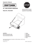
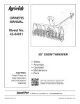
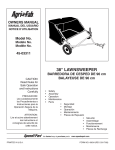
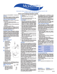
OWNERS
MANUAL
SH IE LD
UP - 8
TO 18
SH IE LD
FT . SP
DO W N
RE AD
W ID TH
- 3 TO
4 FT . SP
RE AD
W ID TH
Model No.
45-02101-101
PRO 125#
BROADCAST SPREADER
CAUTION:
Read Rules for
Safe Operation
and Instructions
Carefully
Assembly
Operation
Maintenance
Repair Parts
PRINTED IN U.S.A.
FORM NO. 47438 (Rev. 2/00)
TABLE OF CONTENTS
SAFETY RULES...............................................................2
CARTON CONTENTS......................................................2
ASSEMBLY ......................................................................4
OPERATION ....................................................................8
MAINTENANCE & STORAGE............................................9
LUBRICATION..................................................................9
PARTS EXPLOSION.......................................................10
REPAIR PARTS..............................................................11
RULES FOR SAFE OPERATION
Any power equipment can cause injury if operated improperly or if the user does not understand how to operate the equipment.
Exercise caution at all times, when using equipment.
1. Do not allow anyone to operate the broadcast spreader
without proper instructions.
2. Do not permit children to operate the broadcast
spreader.
3. Wear eye protection when handling and when applying lawn chemicals.
4. Read the product label for instructions and cautions on
proper handling and application of lawn chemicals.
5. Keep all nuts, bolts and screws tight to be sure
equipment is in safe working condition.
6. Follow maintenance and lubrication instructions as
outlined in this manual.
LOOK FOR THIS SYMBOL TO POINT OUT IMPORTANT SAFETY PRECAUTIONS.
IT MEANS -- ATTENTION! BECOME ALERT! YOUR SAFETY IS INVOLVED.
CARTON CONTENTS (LOOSE PARTS IN CARTON)
Your broadcast spreader carton contains parts as shown in the carton contents diagram below. The
hardware package contains parts shown on page 3. Identify all parts and lay out as shown.
1.
2.
3.
4.
5.
6.
7.
Hopper Assembly
Drive Wheel
Idler Wheel
Spreader Shield
Braces
Flow Control Rod
Vinyl Hopper Cover
8.
9.
10.
11.
12.
13.
14.
2
Hopper Screen
Handle Tube (Short)
Flow Control Arm
Handle Tube (Long)
Leg Stand Tube
Flow Control Gauge
Flow Control Mount Bracket
3
4
5
1
11
10
7
6
9
8
CARTON CONTENTS
2
13
12
14
FULL SIZE HARDWARE REFERENCE CHART
J
A
C
B
D
E
K
M
L
I
H
F
G
NOT SHOWN FULL SIZE
N
O
P
Q
R
S
T
U
V
REF.
QTY.
A
B
C
D
E
F
G
H
I
J
K
3
2
6
2
6
16
17
5
4
1
1
DESCRIPTION
Bolt, Carriage 1/4" x 3/4"
Bolt, Hex 1/4" x 5/8"
Bolt, Hex 1/4" x 3/4"
Bolt, Hex 1/4" x 1-1/2"
Bolt, Hex 1/4" x 1-3/4"
Nut, Hex Lock 1/4-20
Washer, 5/16"
Washer, Nylon
Washer, 3/4"
Cotter Pin, 3/32" x 3/4"
Cotter Pin, 1/8" x 1-1/2"
3
REF.
QTY.
L
M
N
O
P
Q
R
S
T
U
V
1
1
4
1
2
1
1
2
1
1
2
DESCRIPTION
Spacer Tube, Short (1")
Spacer Tube, Long (1-5/16")
Bracket, Swivel
Link, Flow Control
Bracket, Angle Stop
Spring, Extension
Knob, Hand
Knob, Plastic 1/4"
Grip, Control Arm
Cap, Vinyl
Grip, Handle
5. Place the short spacer tube and a 3/4" washer onto the
end of the axle that has the large drilled hole (left hand
side). See figure 2.
ASSEMBLY INSTRUCTIONS
TOOLS REQUIRED FOR ASSEMBLY
(1)
(2)
(2)
6. Place the drive wheel onto the axle. The notched hub
and the air valve should face to the outside. See figure
2.
Pliers
7/16" Open End or Box Wrenches
9/16" Open End or Box Wrenches
7. Fasten the wheel to the axle using a 1/4" x 1-3/4" hex
bolt and a 1/4" hex lock nut. See figure 2.
REMOVAL OF PARTS FROM CARTON
Refer to carton contents on page 2 and to the hardware chart
on page 3 to lay out and identify parts and hardware needed
to assemble the spreader.
SHAFT
SUPPORT
PLATE
SHORT
SPACER
TUBE
1/4" x 1-3/4"
HEX BOLT
ASSEMBLY OF SPREADER
1. Place the spreader upside down.
2. Assemble the long spacer tube and a 3/4" washer onto
the end of axle of the axle that has the small drilled hole
(right hand side). See figure 1.
1/4" HEX
LOCK NUT
3/4" WASHER
3. Place the idler wheel (no notch in hub) onto the axle. The
air valve should face to the outside. See figure 1.
DRIVE
WHEEL
FIGURE 2
4. Assemble one or two more 3/4" washers onto the axle
and then assemble the 1/8" x 1-1/2" cotter pin.
8. Tip the spreader over to rest on the front edge of the
hopper and on the wheels.
SMALL
HOLE
SHAFT
SUPPORT
PLATE
9. Remove the middle 3/8" hex bolt, flat washer and hex
lock nut that fasten the shaft support plate to the
crossover tube. Do not loosen or remove the two
outer bolts. See figure 3.
IDLER
WHEEL
CROSSOVER
TUBE
LONG
SPACER
TUBE
SHAFT
SUPPORT
PLATE
3/4" WASHERS
REMOVE
MIDDLE 3/8"
BOLT, WASHER
AND NUT
1/8" x 1-1/2"
COTTER PIN
FIGURE 1
FIGURE 3
4
14. Assemble the leg stand tube to the handle tube (long)
using two 1/4" x 1-1/2" hex bolts and two 1/4" hex lock
nuts. Tighten. See figure 5.
10. Assemble the (long) handle tube to the side of the
crossover tube opposite the shaft support plate, as
shown in figure 4. Fasten the handle tube to the middle
hole using the bolt, flat washer and hex lock nut which
you removed in step 9. Do not tighten yet.
15. Place the vinyl cap on the leg stand tube. See figure 5.
IMPORTANT: DO NOT assemble the handle tube to the
side of the crossover tube where the shaft support plate is
located. When the spreader is placed in the upright position,
the handle tube must be on to the top side of the crossover
tube. Refer to figure 17 on page 9.
HANDLE TUBE (LONG)
VINYL CAP
1/4" HEX
LOCK NUT
11. Assemble the end of a handle brace to the inside of each
leg of the hopper tube frame, using a 1/4" x 1-3/4" hex
bolt and 1/4" lock nut for each brace. See figure 4. Do
not tighten yet.
1/4" x 1-1/2"
HEX BOLTS
12. Assemble the other end of both handle braces to the
handle tube using a 1/4" x 1-3/4" hex bolt and 1/4" hex
lock nut. Do not tighten yet. See figure 4
LEG
STAND
TUBE
13. Tighten in sequence the bolts and nuts that were
assembled in steps 10, 11 and 12.
HANDLE TUBE (LONG)
HEX BOLT
1/4" x 1-3/4"
1/4" HEX
LOCKNUT
FIGURE 5
MIDDLE BOLT,
WASHER & NUT
16. Assemble the flow control link (the long end with the
small hole) to the flow control arm using one 1/4" x 5/8"
hex bolt and one 1/4" hex lock nut. Do not over tighten.
The flow control link must pivot freely. See figure 6.
HANDLE
BRACE
17. Place the vinyl grip on the flow control arm. See figure
6.
VINYL GRIP
SHAFT
SUPPORT
PLATE
CROSSOVER
TUBE
FLOW CONTROL
LINK
HEX BOLT
1/4" x 1-3/4"
1/4" HEX
LOCK NUT
FIGURE 4
SMALL HOLE
FIGURE 6
5
FLOW
CONTROL
ARM
1/4" x 5/8"
HEX BOLT
21. Hook the free end of the flow control rod through the hole
in the slide gate bracket located near the bottom of the
hopper. See figure 9.
18. Assemble the flow control arm to the flow control mounting bracket using one 1/4" x 5/8" hex bolt and one 1/4"
hex lock nut. Do not over tighten. The flow control arm
must pivot freely. See figure 7.
19. Hook one end of the spring through the hole at the bend
in the flow control rod. Hook the other end in the hole in
the flow control mounting bracket. See figure 7.
SLIDE
GATE
BRACKET
HOPPER
FLOW CONTROL ARM
FLOW CONTROL
MOUNTING BRACKET
FLOW
CONTROL
ROD
FLOW
CONTROL
ROD
FIGURE 9
EXTENSION
SPRING
1/4" HEX LOCK NUT
22. Assemble the flow control mounting bracket and the
short handle tube to the long handle tube using two 1/4"
x 1-3/4" hex bolts, two 5/16" flat washers and two 1/4"
hex lock nuts. See figure 10. Do not tighten yet.
1/4" x 5/8"
HEX BOLT
FIGURE 7
23. Place a handle grip on each handle tube. See figure 10.
20. Place a 5/16" flat washer over the end of flow
control rod and insert the rod through the slot in the
flow control mount bracket and through the hole in
the flow control link. Secure with a 3/32" x 3/4"
cotter pin. See figure 8.
FLOW CONTROL
MOUNTING BRACKET
1/4" x 1-3/4"
HEX BOLTS
FLOW
CONTROL
ROD
EXTENSION
SPRING
FLOW
CONTROL
LINK
5/16"
5/16"
FLAT
FLAT
WASHERS
WASHERS
5/16" FLAT
WASHER
FLOW CONTROL
MOUNTING BRACKET
HANDLE
TUBE
(SHORT)
FIGURE 10
3/32" x 3/4"
COTTER
PIN
FIGURE 8
6
HANDLE
TUBE
(LONG)
1/4" HEX
LOCK NUTS
HANDLE GRIP
24. Assemble the flow control gauge onto the flow control
mounting bracket using a 1/4" x 3/4" carriage bolt, a
nylon washer and the hand knob. See figure 11.
28. Assemble the spreader shield to the front swivel brackets using two 1/4" x 3/4" carriage bolts, 5/16" washers
and the two 1/4" plastic knobs. See figure 13.
25. Push the flow control arm forward to the off position and
slide flow control mounting bracket toward hopper until
closure plate (bottom of hopper) is fully closed. Carefully
tighten the 1/4" hex lock nuts without deforming the
slots. The closure plate should open half way when the
flow control gauge is set at "5". Reposition the flow
control mounting bracket as necessary. See figure 11.
29. Assemble the spreader shield to the rear swivel brackets
using two 1/4" x 3/4" hex bolts, four 5/16" washers and
two 1/4" hex lock nuts. Tighten the locknuts so that the
swivel bracket can still pivot freely. See figure 13.
5/16" WASHER
PLASTIC
KNOB
HAND KNOB
NYLON
WASHER
OFF
FLOW CONTROL
GAUGE
1/4" x 3/4"
CARRIAGE BOLT
1/4" HEX
LOCK NUTS
1/4" LOCK NUT
1/4" x 3/4"
CARRIAGE BOLT
FLOW CONTROL
MOUNTING BRACKET
FIGURE 13
FIGURE 11
26. Attach an angle stop bracket (inside) and a swivel
bracket (outside) to the rear hole in the R.H. shield
bracket using a 1/4" x 3/4" hex bolt, two 5/16" washers,
a nylon washer and a 1/4" hex lock nut. Tighten the
locknut so that the swivel bracket can pivot freely. See
figure 12. Repeat step on L.H. shield bracket.
30. Place the hopper screen down into the hopper to help
break up clumpy material and to prevent large clumps
from reaching the bottom of the hopper and clogging the
opening. See figure 14.
27. Attach a swivel bracket to the front hole in the R.H. shield
bracket using a 1/4" x 3/4" hex bolt, two 5/16" washers,
a nylon washer and a 1/4" hex lock nut. Tighten the
locknut so that the swivel bracket can pivot freely. See
figure 12. Repeat step on L.H. shield bracket.
5/16"
WASHER
1/4" HEX
LOCK NUT
1/4" x 3/4"
HEX BOLT
NYLON
WASHER
HOPPER SCREEN
1/4" x 3/4"
HEX BOLT
NYLON
WASHER
FIGURE 14
ANGLE STOP
SHIELD
BRACKET
BRACKET
SWIVEL
BRACKET
FIGURE 12
7
USING THE SPREADER
OPERATION
1. Determine approximate square footage of area to be
covered and estimate amount of fertilizer or seed required.
2. With flow control arm in off position, set flow rate gauge
at number indicated in flow rate chart for light or heavy
application rate. Also refer to instructions on bag for
manufacturers recommended settings.
3. With the flow control arm set at the off position, fill the
hopper with up to 125 pounds of material, breaking up
lumpy fertilizer as you fill hopper. The hopper screen
helps prevent any large lumps from clogging the opening in the bottom of the hopper.
4. To broadcast, always start the spreader in motion before
opening the closure plate.
5. Walk at a brisk pace when spreading. The application
charts are based on a ground speed of 3 m.p.h. which
equals travelling 100 feet in 23 seconds.
6. Overlap the spread pattern to insure uniform coverage
at the edges. Approximate distance between each pass
is shown in the application diagrams in figure 16.
7. When using weed control fertilizers make sure the
broadcast pattern does not hit evergreen trees, flowers
or shrubs. The spreader shield may be lowered to limit
the dispersal pattern. Adjust the flow control according
to the application chart on page 9.
8. Do not allow the spreader to sit stationary with the flow
control arm in ON position. If fertilizer is accidentally
deposited too heavily in a small area, soak the area
down thoroughly with a garden hose to prevent burning
of the lawn.
STARTING THE SPREADER
1. Pull the flow control arm back against the flow control
gauge for the "ON" position. This opens the closure plate
in the bottom of the hopper and starts the material flow.
See figure 15.
2. Always start the spreader in motion before moving the
flow control arm to the on position.
STOPPING THE SPREADER
1. Push the flow control arm forward for the "OFF" position.
This closes the closure plate in the bottom of the hopper
and stops the material flow. See figure 15.
2. Always move the flow control arm to the off position while
the spreader is still in motion.
SETTING THE FLOW RATE
1. Move the flow control arm to the "OFF" position.
2. Determine the proper flow rate setting by referring to the
application charts on page 9 and to the instructions on
the chemical package.
3. Loosen the hand knob and move the flow control gauge
to the recommended setting and retighten the hand
knob. See figure 15.
FLOW
CONTROL
ARM
OFF
-ON
HAND KNOB
FF
O
FLOW
CONTROL
GAUGE
N
SHIELD UP
O
012
345
678
9 10
8' to
10'
FLOW RATE SETTINGS
FIGURE 15
OVERLAP
SETTING THE SPREADER SHIELD
SHIELD DOWN
SPREADER SHIELD RAISED
For a normal spread pattern used in open areas, loosen the
plastic knob on each side of the shield, raise the shield and
retighten the knobs.
3' to
4'
SPREADER SHIELD LOWERED
For a restricted spread pattern when applying material to a
confined area or next to sensitive plants, loosed the plastic
knob on each side of the shield, lower the shield and
retighten the knobs.
OVERLAP
FIGURE 16
8
IMPORTANT: Application rates (shown on chart) are
affected by humidity and mixture content of material (granular and pellet). Minor adjustment of the flow rate setting may
be necessary to compensate for these variables. The rate
chart is calculated for light and heavy application. The faster
you walk, the wider the broadcast width. A variation in speed
will determine the flow rates and width of broadcast.
LUBRICATION
1.
2.
3.
4.
Apply a little automotive grease to the sprocket and gear.
Oil nylon bushings on sprocket shaft. See figure 17.
Oil axle/shaft bushing on axle as shown in figure 17.
Oil right hand wheel bearing as needed.
NOTE: We do not recommend the use of powdered
materials due to difficulty in obtaining a satisfactory or
consistent broadcast pattern.
OIL
APPLICATION CHART (SHIELD UP)
TYPE
MATERIAL
FERTILIZER
Powder
Granular
Pelleted
Organic
GRASS SEED
Fine
Coarse
ICE MELTER
FLOW SETTING
3 MPH
(100 FT. IN 23 SEC.)
SPREAD
WIDTH
IN FEET
3-5
3-5
3-5
6-8
3-4
8 - 10
10 - 12
6-8
3-4
4-5
6-8
OIL
OIL
6-7
8-9
10 - 12
FIGURE 17
MAINTENANCE & STORAGE
APPLICATION CHART (SHIELD DOWN)
TYPE
MATERIAL
FERTILIZER
Powder
Granular
Pelleted
Organic
GRASS SEED
Fine
Coarse
ICE MELTER
FLOW SETTING
3 MPH
(100 FT. IN 17 SEC.)
SPREAD
WIDTH
IN FEET
1-3
1-3
1-3
3-4
3-4
3-4
3-4
3-4
1-3
2-3
2-4
3-4
3-4
3-4
SPROCKET
SHAFT
GREASE
1. Do not store spreader with any material in hopper.
2. Clean your spreader after use. Flush thoroughly with
water.
3. If for any reason the axle, gear and sprocket assembly
is disassembled, be sure to mark position of parts as
they are removed. Drive wheel and sprocket position
determine relation direction of spreader plate. With
reassembly of gear and sprocket use shim washers as
needed for minimum backlash. Add grease to gear and
sprocket.
4. If agitator wire becomes damaged or worn it can be
replaced. Loosen 3/8" hex nut at top end of sprocket
shaft until agitator wire is free. Remove old agitator wire
from hole in agitator sleeve and replace with new agitator wire. Position agitator wire so that sprocket shaft
turns freely and tighten 3/8" hex nut on top of sprocket
shaft. See figure 18.
SPROCKET
SHAFT
3/8" HEX NUT
AGITATOR
WIRE
AGITATOR
SLEEVE
FIGURE 18
9
REPAIR PARTS FOR BROADCAST SPREADER MODEL 45-02101-101
68
39
61 64
E
67 64
F
65
63
9
64
48
59
64
61
44
52 39
55
14
41
17
55
70
42 64
38
9 8
37
1
37
71
40
29
72
31
5 9
39
30
53 2
60
4
33
9
D
9
62
10
D
13
37
A
35
32
56
C
37
19
22 20
12
49
58
36
11
69 64
47
9
57
46
53
37
B
64
9
6
E
F
9
63
64
A
34
27
66
37
54
61
3
25
37
9
40
38
7
26
64
45
9
9
19
18
21
9
21
43
4
C
51
50
51
B
28 23
51
35
23
16
9
9
10
24
15
REPAIR PARTS FOR BROADCAST SPREADER MODEL 45-02101-101
REF.
NO.
PART
NO.
QTY.
1
2
3
4
5
6
7
8
9
10
11
12
13
14
15
16
17
18
19
20
21
22
23
24
25
26
27
28
29
30
31
32
33
34
35
36
44466
43882
62482
44462
23753
23758
43648
23756
43013
43808
43084
43086
43064
44463
44456
44457
44464
23752
43851
43871
1540-032
1540-162
44798
44494
47437
04367
43850
44500
C-9M5732
23766
43878
43070
44468
44514
23525
23762
1
4
1
1
1
1
2
1
24
1
2
2
2
1
1
1
1
1
2
1
5
1
2
1
1
1
1
1
2
1
1
5
1
1
2
1
DESCRIPTION
REF.
NO.
Hopper
Rivet, Stainless
Ass'y, Guide Closure
Tube, Frame
Slide Gate Angle Bracket
Slide Gate Bracket
Bolt, Hex 1/4-20 x 1-1/2" Lg.*
Flow Control Link
Nut, Hex Lock 1/4-20 Thd. *
Tube, Crossover
Bolt, Hex 5/16-18 x 1-3/4" Lg. Gr. 5
Lock Washer, 5/16"*
Nut, Hex 5/16-18 Thd.*
Tube, Handle (Long)
Wheel Ass'y. 14" x 4"
Wheel Ass'y. (W/Hole) 14" x 4"
Tube, Handle (Short)
Shaft, Axle
Pin, Spring 3/16" Dia. x 1-1/4" Lg.
Bushing, Axle Shaft
Washer, Flat .78" I.D.
Washer, Flat 3/4" Std.
Bearing, Flange
Tube, Spacer
Shaft, Impeller
Spreader Plate
Pin, Spring 1/8" Dia. x 5/8" Lg.
Spacer, 1" O.D. x 1" Lg.
Rivet, Pop
Sleeve, Agitator
Wire, Agitator
Washer, Flat 3/8"
Sprocket - 6 Tooth
Rod, Flow Control
Brace, Hitch
Support, Shaft
11
37
38
39
40
41
42
43
44
45
46
47
48
49
50
51
52
53
54
55
56
57
58
59
60
61
62
63
64
65
66
67
68
69
70
71
72
PART
NO.
QTY.
1509-069 12
43866
2
1543-069 11
43088
9
23755
1
23754
1
62474
1
23759
1
44101
1
23533
1
43000
1
43848
1
44481
1
43093
1
43009
4
43849
1
44285
2
43054
1
44482
2
43082
3
41576
2
44465
1
43962
1
44566
1
43012
7
46055
1
44950
3
R191111116 17
46119
1
24125
2
46120
2
23998
4
23999
2
47441
1
43015
1
43003
1
47438
1
DESCRIPTION
Bolt, Hex 1/4-20 x 1-3/4" Lg. *
Bolt, Hex 1/4-20 x 5/8" Lg. Gr. 5*
Washer, Nylon
Washer, Flat 1/4" Std.
Gage, Flow Control
Bracket, Flow Control Mount
Gear Assembly
Flow Control Arm
Cotter Pin 3/32" x 3/4" Lg.*
Plate, Closure
Spring, Extension
Grip, Flow Control Arm
Cap, Vinyl
Cotter Pin, 1/8" x 101/2" Lg.
Washer, 1-5/8" O.D. x 25/32" I.D.
Knob, Plastic 1/4-20 Thd.
Bushing, Delrin 3/8" I.D.
Bolt, Hex 3/8-16 x 2" Lg. Gr. 5
Grip, Handle
Nut, Hex Lock 3/8-16 Thd.
Bolt, Hex 3/8-16 x 1-3/4" Lg. Gr. 5
Tube, Leg Stand
Optional Vinyl Hopper Cover
Spring, Torsion
Bolt, Hex 1/4-20 x 3/4" Lg. Gr. 5
Pin, Spring 1/8" x 1" Lg.
Bolt, Carriage 1/4-20 x 3/4" Lg.
Washer, Flat 5/16"
Shield, Spreader
Bracket, Shield
Knob, Plastic
Bracket, Swivel
Bracket, Angle Stop
Screen, Spreader
Nut, Hex 3/8-16 Thd.
Lock Washer, 3/8"
Owner's Manual
REPAIR PARTS
303 West Raymond
Sullivan, IL. 61951
(217) 728-8388 / www.agri-fab.com