1
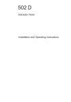
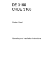
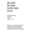
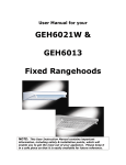
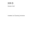
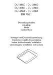
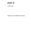
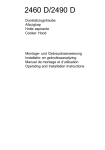
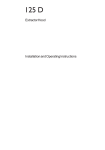
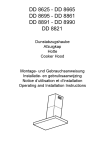
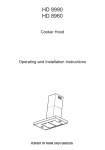
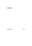
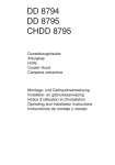
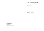
HL 7275 DL 7275 Dunstabzugshaube Afzuigkap Hotte Cooker Hood Campana extractora Montage- und Gebrauchsanweisung Installatie- en gebruiksaanwijzing Notice dutilisation et dinstallation Operating and Installation Instructions Instrucciones de montaje y manejo Contents Safety warnings .............................................................................. 46 For the user ...................................................................................... 46 For the installer ................................................................................. 47 Description of the Appliance ......................................................... 49 Extraction ......................................................................................... 49 Recirculation Mode ........................................................................... 49 Control Panel .................................................................................. 50 Maintenance and care .................................................................... 51 Cleaning the hood ............................................................................ 51 Metal grease filter ............................................................................. 51 Removing the metal grease filter ...................................................... 51 Charcoal filter ................................................................................... 52 Changing the light bulb ..................................................................... 53 What to do if ................................................................................... 54 Special accessories ........................................................................ 54 Service and Spare Parts ................................................................. 55 Customer Care Department ............................................................. 55 Technical Details ............................................................................ 56 Mounting accessories included ......................................................... 56 Electrical connection ..................................................................... 56 Installation ........................................................................................ 57 45 Safety warnings For the user The cooker hood is designed to extract unpleasant odours from the kitchen, it will not extract steam. Always cover lighted elements, to prevent excess heat from damaging the appliance. In the case of oil, gas and coal fired cookers it is essential to avoid open flames. Also, when frying, keep the deep frying pan on the cooker top/ cooker under careful control. The hot oil in the frying pan might ignite due to overheating. The risk of self-ignition increases when the oil being used is dirty. It is extremely important to note that overheating can cause a fire. Never carry out any flambé cooking under the hood. Always disconnect the unit from the power supply before carrying out any work on the hood, including replacing the light bulb (take the cartridge fuse out of the fuse holder or switch off the automatic circuit breaker). It is very important to clean the hood and replace the filter at the recommended intervals. Failure to do so could cause grease deposits to build up, resulting in a fire hazard. The appliance is not intended for use by young children or infirm persons without supervision. Older children must be supervised if using the appliance. Young children should be supervised to ensure that they do not play with the appliance. WARNING - Ensure that the appliance is switched off before replacing the lamp to avoid the possibility of electric shock. This appliance is marked according to the European directive 2002/96/ EC on Waste Electrical and Electronic Equipment (WEEE). By ensuring this product is disposed of correctly, you will help prevent potential negative consequences for the environment and human health, which could otherwise be caused by inappropriate waste handling of this product. The symbol on the product, or on the documents accompanying the product, indicates that this appliance may not be treated as household waste. Instead it shall be handed over to the applicable collection point for the recycling of electrical and electronic equipment. Disposal must be carried out in accordance with local environmental regulations for waste disposal. For more detailed information about treatment, recovery and recycling of this product, please contact your local city office, your household waste disposal service or the shop where you purchased the product. 46 For the installer When used as an extractor unit, the hood must be fitted with a 150mm diameter hose. Attention: The hose is not supplied and must be purchased separately. Should there already be a pipe of diameter 125 or 120 mm that ducts to the outside through the walls, it is possible to use the 150/ 125-120 mm reduction flange provided. In this case the hood will be slightly noisier. When installing the hood, make sure you respect the following minimum distance from the top edge of the cooking hob/ring surfaces: electric cookers 500 mm gas cookers 700 mm The hood can be installed above these heights but for optimum performance it should be installed at the distance quoted for the appropriate heat source. The national Standard on fuel-burning systems specifies a maximum depression of 0.04 mbar in such rooms. The air outlet must not be connected to chimney flues or combustion gas ducts. The air outlet must under no circumstances be connected to ventilation ducts for rooms in which fuel-burning appliances are installed. The air outlet installation must comply with the regulations laid down by the relevant local authorities. When the unit is used in extraction mode, a sufficiently large ventilation hole must be provided, with dimensions that are approximately the same as the outlet hole. National and regional building regulations impose a number of restrictions on using hoods and fuel-burning appliances connected to a chimney, such as coal or oil room-heaters and gas fires, in the same room. Hoods can only be used safely with appliances connected to a chimney if the room and/or flat (air/environment combination) is ventilated from outside using a suitable ventilation hole approximately 500-600 cm2 large to avoid the possibility of a depression being created during operation of the hood. If you have any doubts, contact the relevant controlling authority or building inspectors office. Since the rule for rooms with fuel burning appliances is outlet hole of the same size as the ventilation hole, a hole of 500-600 cm2, which is to say a larger hole, could reduce the performance of the extractor hood. 47 If the hood is used in its recirculation mode, it will operate simply and safely in the above conditions without the need for any of the aforementioned measures. When the hood is used in its extraction mode, the following rules must be followed to obtain optimal operation: - short and straight outlet hose - keep bends in outlet hose to a minimum - never install the hoses with an acute angle, they must always follow a gentle curve. - keep the hose as large as possible (preferably the same diameter as the outlet hole). - the length should be no more than: 3 metres with one 90° bend 2 metres with two 90° bends Bends of more than 90° will reduce the efficiency of the hood and reduce the airflow. Failure to observe these basic instructions will drastically reduce the performance and increase the noise levels of the extractor hood. 48 Description of the Appliance The cooker hood is designed to extract unpleasant odours from the kitchen, it will not extract steam. The hood is supplied as an extractor unit and can also be used with a recirculation mode by fitting a charcoal filter. In some models the charcoal filter is supplied. The hood, therefore, can be used immediately in the recirculation mode. We advise Hose* removing the charcoal filter to use Cabinet the hood in the extraction mode. Coupling ring Extraction In this version fumes are extracted to the outside via a hose connected to the coupling ring. Fig. 1. In order to obtain the best performance the hose should have a diameter equal to the outlet hole. * The hose is not supplied and Should there already be a pipe of must be purchased separately. diameter 125 or 120 mm that ducts Fig. 1 to the outside through the walls, it is possible to use the 150/125-120 Hose* mm reduction flange provided. In this case the hood will be slightly Cabinet noisier. Recirculation Mode The air is filtered through a charcoal filter and returned to the kitchen. Fig. 2. You will need an original charcoal filter for the filtering function. (See Special Accessories). Charcoal filters * The hose is not supplied and must be purchased separately. Fig. 2 49 Control Panel Best results are obtained by using a low speed for normal conditions and a high speed when odours are more concentrated. Turn the hood on a few minutes before you start cooking, you will then get an under pressure in the kitchen. The hood should be left on after cooking for about 15 minutes or until all the odours have disappeared. The control switches are located on the units front panel. light switch motor switch Fig. 3 the light switch switches the hood lamp on and off the motor switch switches the motor on and off, enabling you to select one of the three different speeds. 50 Maintenance and care The hood must always be disconnected from the electricity supply before beginning any maintenance work. Cleaning the hood Clean the outside of the hood using a damp cloth and a mild detergent. Never use corrosive, abrasive or flammable cleaning products. Never insert pointed objects in the motors protective grid. Wash the outside surfaces using a delicate detergent solution. Never use caustic detergents or abrasive brushes or powders. Only ever clean the switch panel and filter grill using a damp cloth and delicate detergents. It is extremely important to clean the unit and change the filters at the recommended intervals. Failure to do so will cause grease deposits to build up that could constitute a fire hazard. Metal grease filter The purpose of the grease filters is to absorb grease particles which form during cooking and it must always be used, either in the external extraction or internal recycling function. Attention: the metal grease filters must be removed and washed, either by hand or in the dishwasher, every four weeks. Removing the metal grease filter Pull the handle downwards. Fig. 4. Fig. 4 Handle Hand washing Soak grease filters for about one hour in hot water with a greaseloosening cleaner, then rinse off thoroughly with hot water. Repeat the process if necessary. Refit the grease filters when they are dry. 51 Dishwasher Place grease filters in the dishwasher. Select most powerful washing programme and highest temperature, at least 65°C. Repeat the process. Refit the grease filters when they are dry. When washing the metal grease filter in the dishwasher a slight discolouration of the filter can occur, this does not have any impact on its performance. Clean the inner housing using a hot detergent solution only (never use caustic detergents, abrasive powders or brushes). Charcoal filter The charcoal filter should only be used if you want to use the hood in the recirculation function. To do this you will need an original charcoal filter (available from your local Service Force Centre). This filter cannot be cleaned or reused. As a general rule, the charcoal filter(s) should be changed once every four months. Fitting. Remove the frame pushing the two side release keys "a". Fig. 5a-b. Fit each charcoal filter so to cover the plastic grid that protect the fan wheel, then turn clockwise the central handle of the charcoal filter. Fig. 6. Refit the frame (snap into place). To remove proceed in the reverse order. Always specify the hood model code number and serial number when ordering replacement filters. This information is shown on the rating plate located on the inside of the unit. The charcoal filter can be ordered from your local Service Force Centre. a a a b b Fig. 6 Fig. 5 52 Warning Failure to observe the instructions on cleaning the unit and changing the filters will cause a fire hazard. You are therefore strongly recommended to follow these instructions. The manufacturer declines all responsibility for any damage to the motor or any fire damage linked to inappropriate maintenance or failure to observe the above safety recommendations. Changing the light bulb Disconnect the cooker hood from the mains supply. Remove the frame pushing the two side release keys. Replace the old bulb with a new one of the same type. Refit the frame (snap into place). If the light does not come on, make sure the bulb has been inserted in correctly before contacting your local Service Force Centre. 53 What to do if If your appliance fails to work properly please carry out the following checks. Symptom Solution The cooker hood will not start... Check that: The hood is connected to the electricity supply. Check that a fan speed has been selected The cooker hood is not working effectively.. Check that: The fan speed is set high enough for the task. The grease filters are clean. The kitchen is adequately vented to allow the entry of fresh air. If set up for recirculation, check that the charcoal filter is still effective. If set up for extraction, check that the ducting and outlets are not blocked. The cooker hood has switched off during operation... The safety cut-out device has been tripped. Turn off the hob and then wait for the device to reset. If the hood has been installed below the heights indicated in the installation instructions the motor will cut-out frequently which will damage the hood. If after all these checks, the problem persists, contact your local Service Force Centre, quoting the model and serial number. Please note that it will be necessary to provide proof of purchase for any in-guarantee service calls. In-guarantee customers should ensure that the above checks have been made as the engineer will make a charge if the fault is not a mechanical or electrical breakdown. Special accessories Charcoal filter Type 200 54 Service and Spare Parts In the event of your appliance requiring service, or if you wish to purchase spare parts, contact your local Service Force Centre by telephoning: 08705 929 929 Your call will be automatically routed to the Service Centre covering your post code area. For the address of your local Service Force Centre and further information about Service Force, please visit the website at www.serviceforce.co.uk Please ensure that you have read the section What to do if.... as the engineer will make a charge if the fault is not a mechanical or electrical breakdown even the appliance is under warranty. Please note that proof of purchase is required for inguarantee service calls. Help us to help you Please determine your type of enquiry before writing or telephoning. When you contact us we need to know: Your name Clear and concise details of the fault Address and post code Name and model of the appliance* Telephone number E number* Serial number* * This information can be found on the rating plate, which can be seen when the grease filters are removed. For Customer Services in the Republic of Ireland please contact us at the address below: AEG Electrolux Group (Ire) Ltd Long Mile Road Dublin 12 Republic of Ireland Tel: + 353 (0) 1 4090751 Email: [email protected] CUSTOMER CARE DEPARTMENT For general enquiries concerning your AEG appliance or for further information on AEG products, please contact our Customer Care Department by letter or telephone at the address below or visit our website at www.aeg.co.uk Customer Care Department AEG 55-77 High Street Slough, Berkshire SL1 1DZ 08705 950950 (*) * calls to this number may be recorded for training purposes. 55 Technical Details Model Dimensions: Height Width Depth Maximum absorbed power: Motor absorption: Lighting: Electrical connection Length of the cable: Fuse rating: HL 7275 DL 7275 252 mm 724 mm 289 mm 240 W 200 W 2 x 20 W 220-240 V 150 cm 13A 250V Mounting accessories included 8 screws 2,9 x 16 1 Coupling ring (+ 2 screws 3.5 x 9,5) 1 Multiconnector 150-125-120 Electrical connection for UK only Safety warnings for the electrician Connect the hood to the mains supply via a double pole switch which has 3 mm minimum separation between the contacts. The switch must be accessible at all times. The following is valid in the United Kingdom only: - the wire which is coloured green and yellow must be connected to the terminal which is marked with the letter E or by the earth symbol ( ), or coloured green or green and yellow; - the wire which is coloured blue must be connected to the terminal which is marked with the letter N or coloured black, - the wire which is coloured brown must be connected to the terminal which is marked with the letter L or coloured red. 56 Installation - Fig. 7 This cooker hood is designed to be fitted to a cabinet or similar support. Create an opening in the bottom of the cabinet to insert the cooker hood (1-2). Make a hole on the top of the cabinet to fit the hose and for the electrical cable (3). Fit a hose (4) long enough to reach the outside (if the hood is used in the extractor version) or the top of the cabinet (if the hood is used the hood in the recirculation version). Remove the frame by pushing the two side release keys (5-6). Fix the coupling ring on the exhaust hole of the hood and make connection with the bottom end of the hose (7a-b), seal with tape. Prepare the electrical connection (8). Fit the hood into the opening and fix securely to the cabinet with 8 screws (9). Fit the frame (10 - snap into place). 57 5 4 3 5 5 6 Y 1 X 6 2 X= 694,5(+0.5) Y = 257,5 (+0.5) 8 7 9 9 10 Fig. 7 58 From the Electrolux Group. The world´s No.1 choice. The Electrolux Group is the world´s largest producer of powered appliances for kitchen, cleaning and outdoor use. More than 55 million Electrolux Group products (such as refrigerators, cookers, washing machines,vacuum cleaners, chain saws and lawn mowers) are sold each year to a value of approx. USD 14 billion in more than 150 countries around the world. AEG 55-77 High Street SLOUGH Berks SL1 1DZ http://www.aeg.co.uk AEG Hausgeräte GmbH Postfach 1036 D-90327 Nürnberg http://www.aeg.hausgeraete.de © Copyright by AEG LI2CTD Ed. 04/05