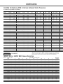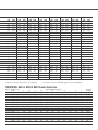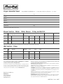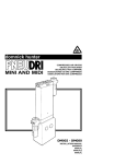
1
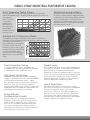
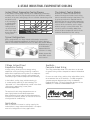
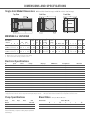
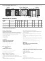
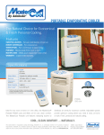
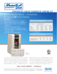
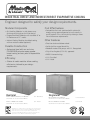
INDUSTRIAL DIRECT AND INDIRECT/DIRECT EVAPORATIVE COOLING
Engineer designed to satisfy your design requirements.
Modular Components
Cost Effectiveness
• Air Handling Modules in side, down or up
discharge and single or dual inlet design.
• Competitive first cost combined with substantial
energy savings over refrigerated air units results in
quick payback. Plus, the simplicity of design allows
low maintenance requirements.
• Evaporative Media Modules with standard 8” or
Hi-Performance 12” media.
• Indirect Cooling Modules for added cooling
with no moisture added (optional).
Other Features
Durable Construction
• Solid shaft for rugged durability.
• Galvanized steel with our exclusive
POLYBOND® polyester epoxy powder
based coating ensures years of dependable
service.
• AdobeAir motors and pumps are U.L. Recognized.
Efficiency
• Precision balanced blower wheel.
• City of Los Angeles (C.O.L.A.) approved.
• AMCA Licensed ratings
• U.L. Classified
• U.L. Listed
• Choice of media modules allows cooling
efficiencies tailored to your design
requirements.
Dual Inlet
Models MD628, MS628, and MU628
U.L. Classified
Shown with 12” media modules DM120
Models UD980 and US980
Single Inlet
Models MD524 and MS524
U.L. Classified
Shown with 12” media modules DM080
U.L. Listed
Shown with 12” media modules UM120
AdobeAir, Inc. certifies that the evaporative air cooling products
shown herein are licensed to bear the AMCA Seal. The ratings
shown are based on tests and procedures performed in
accordance with AMCA Publication 211 and comply with the
requirements of the AMCA Certified Ratings Program.
Models UD960 and US960
Shown with 12” media modules UM080
U.L. Listed
SINGLE-STAGE INDUSTRIAL EVAPORATIVE COOLING
Direct Evaporative Cooling Process
MasterCool Evaporative Media
Direct evaporative cooling exchanges sensible heat for latent heat,
and follows upward along a constant wet-bulb temperature line on the
Psychrometric
Chart. The result
is a dry-bulb
temperature of
the leaving air
(B) approaching
the wet-bulb
temperature of the
entering air (A).
MasterCool evaporative media is constructed
of special cellulose material, impregnated with
insoluble anti-rot salts and rigidifying saturants.
The cross-fluted design continually directs
water to the air-entering side, inducing a highly
turbulent mixing of air and water for optimum
heat and moisture transfer.
Standard and Hi-Performance Models
The flexibility of modular components allows selection of CFM and
saturation efficiencies producing the sensible heat capacities needed to
meet design requirements. For
many applications, our standard
8” media continues to be an
economical choice, with an 80%
saturation efficiency at 450 FPM.
For more demanding design
conditions, our 12” media offers
90% efficiency at around 450
FPM.
Direct Evaporative Cooling
Comfort Levels
Put simply, whenever water is evaporated, heat
is absorbed. This basic principle underlies the design
of the MasterCool direct evaporative cooler.
Not only does evaporative cooling lower the temperature
in the space to be cooled, it also lowers the temperature
you feel. Rapid air movement produced by the
MasterCool increases skin evaporation which causes you
to feel 3-5° effectively cooler than the temperature read
from a thermometer. Evaporative cooling can provide
effective temperatures acceptable in most commercial/
industrial applications throughout the world.
High Quality Construction
Hot-dipped galvanized steel, welded for maximum
strength is combined with our exclusive POLYBOND®
finish that protects the whole system – cabinet
pans, distributor covers, louvers, and all other parts
contacting water. The electrostatically applied
polyester epoxy powder-based coating is cured at high
temperature and is so durable that these models are
backed by the best warranty in the industry.
Energy Efficient...
Environmentally Friendly
With no compressors or condensors, MasterCool
evaporative coolers offer significant energy savings
over mechanical refrigeration units; and, with no
CFC’s, do not contribute to depletion of the ozone
layer. Their air washing effect improves indoor air
quality with fresh, filtered air constantly brought into
the cooled space...forcing stale air out.
Typical Applications
The Industrial MasterCool is used for area cooling or
spot cooling. In many areas it can replace or supplement
mechanical refrigeration needs in agricultural,
institutional, commercial, and industrial applications.
Applications such as kitchens, laundries, gymnasiums,
heat treating areas, and dry cleaning plants requiring
large quantities of fresh air moving through the building
are ideal candidates for evaporative cooling.
2-STAGE INDUSTRIAL EVAPORATIVE COOLING
Indirect/Direct Evaporative Cooling Process
The Indirect Cooling Module
In the indirect cooling stage, entering air is cooled along a horizontal
humidity ratio line on the Psychrometric Chart (A to B) without adding
moisture. In the next cooling stage, this air is further cooled along a new
wet-bulb line (B
to C), resulting in
a lower dry-bulb
temperature of
leaving air than
can be achieved
with single stage
direct evaporative
cooling alone.
Outside air is drawn into the ICM. A fan
draws air through the inside of vertical fins
(which have water running inside them). The
air picks up heat and is expelled from the
ICM while the fins are cooled by evaporation.
Other outside air is drawn across the outside
surfaces of the cooled fins, and is cooled
without coming in contact with water. This
cooled air, with no humidity added, then
enters the direct evaporative section of the
Industrial MasterCool for final cooling.
Typical Configurations
Many configurations of 2-Stage Industrial MasterCool are possible.
Typical field-assembled components include 2 or 3 Indirect Cooling
Modules with Models MD/MS524 and 4 or 6 ICM’s with models MD/MS/
MU628 Contact your
local MasterCool
representative for
assistance in sizing.
Models shown with
three ICM’s at each
inlet location.
2-Stage Indirect/Direct
Evaporative Cooling
KoolKalk...
Computer Aided Sizing
2-Stage cooling allows you to use energy-saving
evaporative cooling technology for design conditions
where direct evaporative cooling alone is not adequate.
A 2-stage cooler results in greater cooling power, less
affected by higher ambient temperature and humidity.
The sizing method described in this brochure can be used
for general sizing of direct evaporative Industrial MasterCool
units.
In the indirect cooling stage, outside entering air
is cooled sensibly reducing its total enthalpy. This
“precooled” air is then evaporatively cooled in the direct
cooling stage, approaching its new, lower
wet-bulb temperature.
The end result is discharge temperatures near or
even slightly below the wet-bulb temperature.
More importantly, these lower discharge temperatures
translate into customer comfort at a fraction of the cost
of refrigerated air conditioning.
Applications
With its substantial increase in cooling capacity, the
indirect/direct 2-stage Industrial MasterCool can replace
mechanical refrigeration in many applications.
For more accurate sizing, and for sizing indirect/direct units,
we recommend the use of KoolKalk... an IBM compatible
computer program designed specifically for AdobeAir
Evaporative Coolers. For more information please visit the
AdobeAir, Inc. website at www.AdobeAir.com.
DIMENSIONS AND SPECIFICATIONS
Single Inlet Model Dimensions
MD524 or UD960 (Down Discharge) and MS524 or US960 (Side Discharge)
Top View
Side View
Front View
MD/MS524 or UD/US960
Media SectionCabinet
Model Number
1 Required
H
W
Drain1
Location
Duct Location
Side
D
A
DM080
or UM080 51½ 491/8 66
DM120
or UM120 51½ 491/8 70
Down
C
E
B
F
G
Media Blower
Cabi- Cabinet
net
J
K
Water2
Service
Location
L
M
Electric3
Service
Location
S
T
Dia. Width
Blower Skid Location
Pulley
Pitch
Shaft Dia. N P Q
R
Blower Wheel
Media
Pad
Dimension Area
X
V Sq.Ft.
26¾ 17
3 11¼ 13 133/8
17
491/8
7¼ 123/8
18 35½
24
24
13/16
13
2 15/8 4 2½ 445/8 48 14.8
26¾ 17
3 11¼ 13 173/8
21
491/8
7¼ 163/8
22 35½
24
24
13/16
13
2 15/8 4 2½ 445/8 48 14.8
1. Drain is 3/4” male hose thread.
2. Water service can be left or right for 1/4” tubing.
3. 7/8” knockout for running electrical service.
Electrical Specifications
HP
Speed
1
2
1
1
2
Phase
1
1
3
1
1
Voltage
115/230
230
208-230/460
115/230
230
Amperage
12.5/6.2
5.9
3.0/1.5
15.1/7.5
7.3
NEMA Frame
56
56
56
56
56
1
1½
1½
2
2
3
1
1
1
1
1
1
3
1
3
1
3
3
208-230/460
115/230
208-230/460
115/230
208-230/460
208-230/460
3.6/1.7
14.5/6.3
4.6/2.2
19.0/8.5
7.1/3.3
8.7-8.4/4.2
143T
143T
143T
143T
143T
182T
5
7½
1
1
3
3
208-230/460
208-230/460
14.2-13.0/6.5
20.9-19.2/9.6
184T
213T
¾
¾
¾
1
1
• Amperage from National Electric Code.
• Single phase motors rated 230 volts can be operated at nameplate amps at 208 volts.
Pump Specifications
Pump
Model#
CP280
CP480
Volts
115
230
Amps
1.2
.6
Watts
80
80
Note: Pumps are available in 115 volt and 230 volt models. As a
result, transforming or separate circuiting may be required for
other voltages.
Motor Kit #
EJ006
EJ020
EJ883
EJ007
58
/
5/8
5/8
5/8
5
/8
7/8
7/8
7/8
7/8
7/8
11/8
11/8
13/8
EJ021
EJ665
EJ212
EJ666
EJ213
EJ667
EJ668
EJ659
EJ675
• See nameplate on actual motor for amperage in figuring overload protector.
• All 3-phase motors listed are suitable for use on evaporative coolers at 200 volts.
Bleed Rates
GPH
At 4’ Head
300
300
Shaft Diameter
GPH per Media Module
Blower Model
¾
524 or 960
628 or 980
7
–
1
8
11
1½
9
13
Blower Motor HP
2
3
10
10
14
16
5
–
18
7½
–
20
Dual Inlet Model Dimensions
MD628 or UD980 (Down Discharge), MS628 or US980 (Side Discharge) and MU628 (Up Discharge)
Top View
Side View - Blower Section
Front View
(UP)
(DOWN)
MD/MS/MU628 or UD/US980
Media Section
Model Number
1 Required
H
Cabinet
Duct Location
Side
W
D
DM080
or UM080 51½ 831/8 491/8
DM120
or UM120 51½ 911/8 491/8
A
B
Drain1
Location
Down
C
E
F
G
Media Blower
Cabi- Cabinet
net
J
K
Water2
Service
Location
L
M
Electric3
Service
Location
S
T
Dia. Width
Blower Skid Location
Pulley
Pitch
Shaft Dia. N P Y Q R
Blower Wheel
Media
Pad
Dimension Area
X
V Sq.Ft.
31¾ 17¾ 15¼ 8¾
13 133/8
17
491/8
71⁄4 123/8
18 35½
28
28
13/16
18 19 15/8 2 4 2½ 445/8 48 14.8
31¾ 17¾ 15¼ 8¾
13 173/8
21
491/8
71⁄4 163/8
22 35½
28
28
13/16
18 23 15/8 4 4 2½ 445/8 48 14.8
1. Drain is 3/4” male hose thread.
2. Water service can be left or right for 1/4” tubing.
3. 7/8” knockout for running electrical service.
Sizing Instructions
Refer to the Electrical Specifications chart on facing page.
Follow these steps to properly size the Industrial MasterCool. The performance or
Sensible Heat Capacity of any cooler is a function of both the CFM and saturation
efficiency (which determines the delivered air discharge temperature). Sizing by
only considering CFM may result in an improperly sized application.
4. Determine the RPM that will deliver the required airflow (CFM) at the static
pressure of the system.
1. Determine design conditions:
5. Determine the sheave, and the number of turns open, that is closest to the
desired RPM.
Outdoor Dry-Bulb DB1
Outdoor Wet-Bulb WB1
Indoor Dry-Bulb T1
2. Determine design sensible heat load (Btuh)
Refer to the Certified Air Delivery CFM chart for the chosen cooler and selected
motor HP.
Refer to the Sheave Selection charts on the next page. Find the selected motor HP,
shaft size, and desired RPM (See Steps 2-4 above). You might need to look at more
than one sheave before finding the correct RPM.
6. Specify the sheave and sheave setting (turns open) for the installer.
3. Determine leaving air temperature (LAT):
LAT = DB1 - [(DB1 - WB ) * EFF]
where EFF ‘ 0.80 for 8” media or 0.90 for 12” media
4. Determine CFM required:
CFM = 0.925 * Sensible Heat Load
(T1 - LAT)
5. Determine the cooler(s) required:
Refer to the specification / air flow charts on next page.
6. Use KoolKalk to account for various losses:
Ordering
When ordering your cooler, you should know this information.
• System design static pressure.
• Desired air volume at system design.
• Electrical power supply available.
• Stability of structure to support operating weight of unit.
Complete systems consist of the following components, and are sold separately
for application versatility.
• Cabinet – 1 blower section
This will result in more accurate sizing.
• Wet media section (1 for 524’s - 2 for 628’s)
Motor Sheave Selection
• Motor
1. Determine the external static pressure of the air delivery system.
• Motor sheave
2. Determine the motor (H.P., Voltage and Phase) required to deliver the design
airflow.
• Pulley-belt kit
3. Determine the shaft size for the motor selected.
• Pump (one required for each media section)
NOTE: Motor starters, internal wiring and over-current protection are not supplied.
DIMENSIONS
Certified Air Delivery CFM at Various External Static Pressures
Inches Water Gauge. AMCA Licensed Ratings.
Operating
Belt information
Model
Weight
BHP
Quantity
Down
Side
524 with DM080 or 960 with UM080 — 8” Media
560
¾
1
AX78
AX80
570
1
1
AX78
AX80
575
1½
1
AX78
AX80
580
2
1
AX78
AX80
590
3
1
AX78
A82*
524 with DM120 or 960 with UM120 — 12” Media
600
¾
1
AX78
AX80
610
1
1
AX78
AX80
615
1½
1
AX78
AX80
620
2
1
AX78
AX80
630
3
1
AX78
A82*
628 with two DM080 or 980 with two UM080 — 8” Media
818
1
1
A95*
A95*
823
1½
1
A95*
A95*
828
2
1
A95*
A95*
838
3
2
A97
A97
858
5
2
A97
A97
898
7½
2
A100*
A100*
628 with two DM120 or 980 with two UM120 — 12” Media
908
1
1
A95*
A95*
913
1½
1
A95*
A95*
918
2
1
A95*
A95*
928
3
2
A97
A97
948
5
2
A97
A97
988
7½
2
A100*
A100*
.0
CFM
.0
RPM
.1
CFM
.1
RPM
.2
CFM
.2
RPM
6390
7030
8050
8860
9050
298
329
376
414
422
6070
6760
7810
8640
9050
310
339
385
422
440
5710
6420
7530
8400
9050
320
349
394
430
459
6250
6880
7880
8670
9050
298
328
376
414
422
5900
6560
7600
8420
9050
309
338
384
421
439
5550
6250
7320
8160
9050
321
349
393
429
458
A95
A95
A95
A95
A95
A95
9720
11130
12250
14020
16620
214
245
270
309
367
9320
10720
11890
13720
16390
18100
224
254
278
316
371
406
8650
10230
11460
13350
16080
18100
235
263
286
323
378
418
A95
A95
A95
A95
A95
A95
9680
11080
12190
13950
16540
18100
216
248
273
312
370
406
9080
10540
11700
13510
16050
18100
226
256
280
318
375
409
8530
10080
11260
13130
15820
18100
237
265
288
325
380
428
Up
Shaded Areas: Do not exceed listed RPM, water entrainment may result.
NOT RECOMMENDED
*Not supplied: MS524 coolers with a 3 HP motor require the purchase of one A82 belt
(AX78 belt included with unit). MD628 and MS628 coolers with 1, 11⁄2 or 2 HP motor
requires one A95 belt (two A97 belts included with unit). MD628 and MS628 coolers
with 71⁄2 HP motor require two A100 belts (two A97 belts included with unit).
MD/MS 524 or UD/US 960 Sheave Selection
Motor HP
Browning
Part #
Bore
5
4½
4
3½
Blower RPM / Sheave Turns Open
3
2½
2
Single Phase Motor Blower RPM @ 1725 Motor RPM / Sheave Turns Open
¾, 1
1VL34 5/8
252
265
279
292
305
¾, 1
1VL40 5/8
318
332
345
358
372
1½, 2
1VL40 7/8
318
332
345
358
372
¾, 1
1VL44 5/8
372
385
398
411
425
1½, 2
1VL44 7/8
372
385
398
411
425
1½, 2
1VP50 7/8
451
464
478
491
504
Three Phase Motor Blower RPM @ 1750 Motor RPM / Sheave Turns Open
¾
1VL34 5/8
256
269
283
296
310
1
1VL34 7/8
256
269
283
296
310
¾
1VL40 5/8
323
337
350
363
377
1, 1½, 2 1VL40 7/8
323
337
350
363
377
¾
1VL44 5/8
377
390
404
417
431
1, 1½, 2 1VL44 7/8
377
390
404
417
431
3
1VL44 11/8
377
390
404
417
431
1½, 2
1VP50 7/8
458
471
485
498
512
3
1VP50 11/8
458
471
485
498
512
1½
1
½
0
MasterCool
Package #
318
385
385
438
438
518
332
398
398
451
451
531
345
411
411
464
464
544
358
425
425
478
478
557
372
438
438
491
491
571
385
451
451
504
504
584
EL114
EL110
EL112
ESH2411
EL685
686
323
323
390
390
444
444
444
525
525
337
337
404
404
458
458
458
538
538
350
350
417
417
471
471
471
552
552
363
363
431
431
485
485
485
565
565
377
377
444
444
498
498
498
579
579
390
390
458
458
512
512
512
592
592
EL114
EL116
EL110
EL112
ESH2411
EL685
684
686
685
.3
CFM
.3
RPM
.4
CFM
.4
RPM
.5
CFM
.5
RPM
.6
CFM
.6
RPM
.7
CFM
.7
RPM
.8
CFM
.8
RPM
.9
CFM
.9
RPM
1.0
CFM
1.0
RPM
5320
6080
7250
8140
9050
333
359
402
438
475
4850
5720
6930
7880
9050
348
371
412
446
491
4200
5280
6630
7590
9050
373
386
422
455
508
3670
4660
6240
7310
8820
391
409
434
464
516
3200
4160
5840
6970
8570
408
426
449
475
524
2770
3720
5260
6630
8330
426
442
471
487
532
2400
3310
4830
6140
8030
443
458
485
505
542
2060
2940
4440
5660
7730
460
473
499
523
552
5170
5910
7040
7920
9050
334
360
403
438
475
4720
5540
6740
7650
9050
349
373
413
447
492
4070
5130
6430
7380
8820
371
386
424
456
509
3590
4510
6070
7100
8570
390
408
435
466
518
3140
4060
5620
6760
8340
407
425
450
476
526
2740
3650
5110
6440
8080
423
441
469
487
534
2340
3270
4710
5930
7790
441
455
484
505
544
1980
2900
4350
5510
7520
458
471
498
520
553
8030
9700
10980
12960
15770
18100
246
273
294
330
384
431
7380
9160
10510
12540
15450
18030
260
283
303
337
390
440
6670
8600
10010
12130
15090
17760
276
294
313
345
396
445
5240
7990
9500
11690
14730
17440
308
307
323
353
402
450
4540
7030
8960
11250
14390
17130
326
329
335
362
409
455
3840
5890
8360
10800
14020
16820
345
354
348
371
416
461
3290
5290
6990
10330
13660
16520
363
371
379
382
423
467
2740
4690
6280
9810
13280
16210
379
387
395
393
430
473
7930
9570
10830
12760
15510
18010
248
274
297
332
386
437
7220
9030
10350
12370
15190
17730
261
285
306
340
393
443
6490
8420
9860
11960
14890
17450
279
296
315
348
399
448
5130
7810
9310
11530
14530
17190
310
310
325
356
406
454
4390
6930
8730
11070
14190
16900
329
330
337
364
412
459
3810
5760
8110
10580
13820
16590
345
358
353
373
419
465
3220
5130
6900
10070
13460
16300
361
374
379
384
426
471
2630
4600
6150
9630
13060
15970
376
388
398
396
433
477
• Power ratings (BHP) does not include drive losses.
• Performance ratings include the effects of evaporative media in the airstream.
• Belt tension should be 20 pounds for “A” section belts.
• Performance shown is for installation type B: Free Inlet, Ducted Outlet.
MD/MS/MU 628 or UD/US 980 Sheave Selection
Motor HP
Browning
Part #
Bore
5
4½
4
3½
Blower RPM / Sheave Turns Open
3
2½
2
Single Phase Motor Blower RPM @ 1725 Motor RPM / Sheave Turns Open
1
1VL40 5/8
230
240
249
259
268
1½, 2
1VL40 7/8
230
240
249
259
268
1
1VL44 5/8
268
278
288
297
307
1½, 2
1VL44 7/8
268
278
288
297
307
1
1VP50 5/8
326
335
345
355
364
1½, 2
1VP50 7/8
326
335
345
355
364
Three Phase Motor Blower RPM @ 1750 Motor RPM / Sheave Turns Open
1, 1½, 2 1VL34 7/8
185
194
204
214
224
1, 1½, 2 1VL40 7/8
233
243
253
263
272
1, 1½, 2 1VL44 7/8
272
282
292
301
311
1, 1½, 2 1VP50 7/8
331
340
350
360
369
3
2VP42 11/8
253
263
272
282
292
3, 5
2VP50 11/8
331
340
350
360
369
5
2VP60 11/8
408
418
428
438
447
7½
2VP60 13/8
408
418
428
438
447
1½
1
½
0
MasterCool
Package #
278
278
316
316
374
374
288
288
326
326
383
383
297
297
335
335
393
393
307
307
345
345
403
403
316
316
355
355
412
412
326
326
364
364
422
422
EL110
EL112
ESH2411
EL685
693
686
233
282
321
379
301
379
457
457
243
292
331
389
311
389
467
467
253
301
340
399
321
399
476
476
263
311
350
408
331
408
486
486
272
321
360
418
340
418
496
496
282
331
369
428
350
428
506
506
EL116
EL112
EL685
686
687
688
689
692
Project Submittal Sheet
Models MD/MS 524, MD/MS/MU 628 — U.L. Classified or UD/US 960, UD/US 980 — U.L. Listed
Project
SHL*
Location
Architect
Engineer
Contractor
Submitted By
Date
*Total design sensible heat load of project.
Blower Section – Motor – Motor Sheave – Pulley and Belt Kit
Ref. No.
Blower Section
Qty.
Model No.
Motor Specifications
Motor HP
Volts
Phase
Amps
Kits
Motor Sheave
Belt
1
2
3
4
*NOTE: Each unit (ready to operate) consists of one blower section, one blower motor, one pulley-belt kit, one motor sheave.
Wet Section – Pump
Ref. No.
Wet Section
Qty.
Model No.
Pump
Quantity
Volts
Amps
GPM
1
2
3
4
*NOTE: Each wet section (ready to operate) consists of one wet module and one pump.
Your local MasterCool Representative of AdobeAir, Inc., is ready to
assist you in unit selection and application.
The world leader in evaporative cooling technology, AdobeAir, Inc. is continually involved in
the process of product improvement. AdobeAir, Inc. therefore reserves the right to change
specifications and/or design without prior notice. To obtain the most current product information
and/or specifications, visit the AdobeAir, Inc. web site at www.AdobeAir.com.
Manufactured in Mexico by:
AdobeAir, Inc.
1450 East Grant St.
Phoenix, AZ 85034
www.AdobeAir.com
MasterCool evaporative coolers and components are designed and tested in accordance with
one or more of the following standards or agencies:
Air Delivery: Data published derived from tests conducted in accordance with A.M.C.A. (Air Movement and Control Assoc.) Standard 210.
Sealant: Water Immersion: per ASTM D870. Flexibility: per ASTM D756. Corrosion Resistance: per
ASTM B117. Cycle Freeze/Thaw: per ASTM C117.
POLYBOND®: Corrosion Resistance: per ASTM B117. Pencil Hardness: per ASTM D3363. Adhesion:
per ASTM D3359. Impact Resistance: per ASTM D2794. Flexibility: per ASTM D522. Specular Gloss:
per ASTM D523. Surface Burning Characteristics of Building Materials (best rating) per U.L. 723
and ASTM E-84.
Pumps: Recognized under the U.L. component recognition program for the application – construction, thermal overload, running overload, and locked rotor protection.
Blower Motors: U.L. Recognized general purpose drip-proof.
Polymeric Materials: Tested in accordance with U.L. 94 and 746C. Covered by City of Los Angeles
Research Reports (C.O.L.A.) RR930224 (for all single phase applications), or RR930190 (for 3
phase applications) Electrical, and RR8141 Mechanical.
L900799A March 2007