1
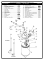
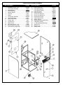
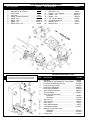
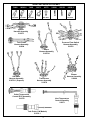
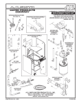
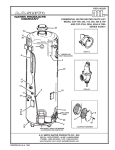
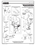
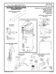
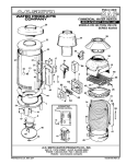
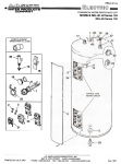
PSD-3-152/a
COMMERCIAL POWER BURNER BOILER
REPLACEMENT PARTS LIST
WIRING/HARNESS & PROBES
See page 8
COPPER BOILERS FOR HYDRONIC
HEATING & HOT WATER SUPPLY
LEGEND MODELS LB/LW: 1000
SERIES 300, 301
PROPANE GAS TRAIN ASSEMBLY
See page 6
NATURAL GAS
TRAIN/BLOWER
ASSEMBLY
See page 5
JACKET/FRAME ASSEMBLY
See page 4
WATERWAYS &
COMBUSTION
CHAMBER
See page 2
CONTROL BOARD
See page 7
BY-PASS
See page 6
EXHAUST & DRAIN
ASSEMBLY
See page 3
WATER INLET
See page 3
A.O. SMITH WATER PRODUCTS CO., INC.
5621 W. 115TH STREET • ALSIP, ILLINOIS 60803
Phone: 1-800-433-2545 • Fax: 1-800-433-2515
Website: www.hotwater.com
PRINTED IN U.S.A. 0502
1
211591-000
LB/LW WATERWAYS & COMBUSTION CHAMBER PARTS LIST
Item Description
Item Description
Part Number
1..... Bracket .................................................. 191602
2..... Burner and Cone Assembly ................... 191850-2
3..... Combustion Chamber Asembly .............. 211592
4..... Connector, Hose ..................................... 191765
5..... Coupling, Flexible w/Gasket .................. 191780-1
6..... Cover Outer ............................................ 210404
7..... Gasket, Outer ........................................ 211594-1
8..... Gasket, Burner ...................................... 191564-1
9..... Gasket, Inner .......................................... 211594
10 .... Housing Assembly ................................ 211635-2
11 ..... Ignitor ..................................................... 192334
12 .... Insulation, Burner ................................... 191618
13 .... Nut, Manifold ......................................... 191555-1
14 .... O-Ring ................................................... 191556-2
15 .... Probe, Outlet Temp./ECO ....................... 210572
16
17
18
19
20
21
22
23
24
24
25
26
27
28
LW Models
LB Models
2
Part Number
.... Probe, Inlet Temp ................................... 210571
.... Screw, #8-32, 3/8" Long, SST ................. 210444
.... Screw, Machine #8-32, 1" Long, SST ..... 191770
.... Sealer, Silicone (not shown) .................. 191482-1
.... Sensor, Flame ........................................ 210421
.... Spacer Ring .......................................... 191554-1
.... Switch, Safety Flow ................................ 211480
.... Tee Assembly ......................................... 192387
.... Tube Assembly, Primary (LW Models) .... 192388
.... Tube Assembly, Primary (LB Models) ..... 192225
.... Tube Assembly, Outlet ........................... 210426
.... Tube Assembly, Secondary .................... 192386
.... Washer, Flat #8 SST .............................. 191768
.... Restrictor-Air, Top Cover ........................ 191926-1
LB/LW EXHAUST, DRAIN & WATER INLET ASSEMBLY PARTS LIST
Item Description
Part Number
Item Description
1 .... Clamp, Hose (Large) .............................. 191794-1
2 .... Clamp, Hose (Small) .............................. 191794-3
3 .... Nut, Hex ................................................. 191817-1
5 .... Drain, Flange ........................................... 191620
6 .... Drain, Flange Assembly .......................... 191625
7 .... Elbow ...................................................... 191664
9 .... Gasket, Drain .......................................... 191622
10 .... Gasket, Vent .......................................... 191683-1
11 .... Nipple ..................................................... 20373-18
12 .... Nut, Hex 1/4" (Serrated) .......................... 210226
13 .... O-Ring .................................................... 191556-1
14 .... Plate, Drain Seal ..................................... 191626
15 .... Pump Ass'y, Circulator (LW Models) ....... 211538
Part Number
16 .... Tube Assembly, Inlet (LW Models) .......... 192308
17 .... Tube Assembly, Primary (LB Models) ..... 192225
18 .... Tube Assembly, Primary (LW Models) ..... 192388
19 .... Tubing, Condensate ................................ 191746
20 .... Tubing, Pressure ..................................... 191562
21 .... U-Bolt Assembly ..................................... 191938
22 .... Valve Drain ............................................... 26273
23 .... Vent Assembly ........................................ 210494
24 .... Vent Flange ............................................ 191685-5
25 .... Washer, Plain ......................................... 76820-18
26 .... Vent Support, Bracket ............................. 192194
27 .... Vent, Restricting Ring (Series 301, LP) .. 191923-1
3
LB/LW JACKET/FRAME ASSEMBLY
Item Description
1
2
3
4
5
6
7
8
9
10
11
12
13
14
15
16
....
....
....
....
....
....
....
....
....
....
....
....
....
....
....
....
Item Description
Part No.
Bolt Machine 5/16” - 18" ...................... 191358-2
Control Panel Assembly ........................ 210601
Display Board ....................................... 210219
Frame Assembly ................................. 210501-1
Gasket, Display .................................... 210130
Grommet ............................................... 97951
Handle .................................................. 191802
Junction Box Assembly ........................ 190438-1
Junction Box Cover .................................. 2233
Label, Control Panel .............................. 210561-1
Locknut, Star ........................................... 1953
Locknut #6 -32 ....................................... 210207
Nipple, Chase ......................................... 41994
Nut, Lock Hex 5/16” - 18" ........................ 97896
Panel Assembly, Left Side .................... 191796-3
Panel Assembly, Right Side .................. 191796-2
17
18
18
19
20
21
22
23
24
25
26
27
28
29
30
31
4
....
....
....
....
....
....
....
....
....
....
....
....
....
....
....
....
Part No.
Panel, Lower Front ............................... 191805-1
Panel, Rear (Natural) .............................. 192191
Panel, Rear (Propane) ............................ 210020
Panel, Top Cover .................................. 191609-1
Plate, Rear Cover ................................... 210214
Screw, Hex Head 5/16” .......................... 210125
Screw, Hex Head #6 -32 ........................ 210206
Switch, Blower Prover ............................ 191666
Switch, Blocked Flue ............................. 191667
Switch , Rocker .................................... 191665-1
Support Bracket (Propane Only) ............. 210017
Transformer (100VA) .............................. 210449
U - Bolt Assembly (Waterway) ............... 191938
Washer, Flat .......................................... 191359
Washer, Lock ........................................ 191480
Switch, Relay ........................................ 211546
LB/LW NATURAL GAS TRAIN/BLOWER ASSEMBLY
Item Description
1 ....
2 ....
3 ....
4 ....
5 ....
6 ....
7 ....
8 ....
9 ....
10 ....
11 ....
12 ....
13 ....
14 ....
15 ....
16 ....
17 ....
18 ....
19 ....
20 ....
21 ....
22 ....
Part No.
Item Description
Blower .................................................. 192195
Blower Adapter Assembly .................... 192215-1
Blower Manifold Assembly .................... 192217
Bracket, Blower .................................... 210214
Clamp, Hose ........................................ 191794-3
Elbow, 1-1/4" ......................................... 192216
Elbow, Union 1-1/4" ............................... 86506-1
Flange, Observation Port ....................... 191573
Gasket, Blower Air Inlet ........................ 192213
Gasket, Burner ..................................... 191564
Gasket, Manifold ................................... 191565
Gasket, Port (1/8" Thick) ...................... 191576
Nut, Hex 1/4", Serrated ......................... 210226
Manifold Assembly - Air/Gas ................ 192309
Nipple, Close 1/8" ................................ 191147-3
Nipple, Close Stainless ........................ 191772-1
Nipple, Tapped ...................................... 86505-3
Nipple, 1-1/4" x 38 1/2" ........................ 86505-28
Nipple, 1-1/4" x 28 3/4" ........................ 86505-27
Nipple, 1-1/4" x 2" .................................. 86505
Nipple, 1-1/4" x 3" ................................. 86505-2
Nipple, 1-1/4" x 4" ................................. 86505-6
Part No.
23 .... Nut, Hex 1/4” ....................................... 191817-1
24 .... Orifice, Air (Series 300 - Nat. Gas) ....... 192737-3
.... Orifice, Air (Series 3011 - L.P. Gas) ...... 192737-2
25 .... Orifice, Union ................. See Orifice Table Below
26 .... Plug, 1/8" Pipe ........................................ 3348
27 .... Port, Observation Lower ........................ 191572
28 .... Port, Observation Upper ....................... 191572-1
29 .... Screen, Air Inlet ................................... 192220-1
30 .... Screw, Cap 1/4" ................................... 190960-2
31 .... Screw, Flathead #8-32 x 1/2" ................ 191542
32 .... Screw, Flathead #8-32 x 3/4" ............... 191542-1
33 .... Switch, Low Gas Pressure ................... 191149-1
34 .... Shutter, Blower ..................................... 192593
35 .... Shutter Flange ...................................... 192592
36 .... Tee, 1/8" ................................................ 40119
37 .... Tee, Pressure ....................................... 191633
38 .... Tubing, Pressure ................................... 191562
40 .... U-Bolt Assembly (Gas Train) ............... 191938-3
41 .... Valve, Main Gas .................................... 78481-3
42 .... Valve, Firing .......................................... 3423-3
43 .... Valve, Solenoid Gas .............................. 192189
44 .... Washer, Plain ...................................... 76820-18
DETAIL BACK VIEW
LEGEND ORIFICE TABLE
Natural
Gas
192222
192222-1
192222-2
-------
Propane
Gas
------192739
192739-1
192739-2
Size
(inches)
0.555
0.537
0.533
0.333
0.329
0.325
Elevation
(Feet)
0-2000
2001-3000
3001-4000
0-2000
2001-3000
3001-4000
5
LB/LW PROPANE GAS TRAIN ASSEMBLY
Item Description
1 ....
2 ....
3 ....
4 ....
5 ....
6 ....
7 ....
8 ....
9 ....
Item Description
Part No.
10
11
12
13
14
15
16
17
18
Valve, Main Gas, LP 300 Series ............. 77780
Regulator, LP 301 Series ...................... 192460
Valve, Firing .......................................... 3423-3
Pipe Plug ................................................ 3348
Switch, Low Gas Pressure ................... 191149-3
Nipple, 1-1/4” ....................................... 86505-13
Nipple, 1-1/4” ....................................... 86505-2
Nipple, 1-1/4” ...................................... 86505-17
Elbow, Union 1-1/4” ................................ 86506
On LB models the circulating pump must be between
the boiler inlet and the bypass (see figure below).
LW
models
have pump
mounted
inside the jacket.
Please
update
these
numbers
....
....
....
....
....
....
....
....
....
Part No.
Elbow, 90 Street 1-1/4” .......................... 94516
Elbow, 90 1-1/4” .................................... 192216
Nipple, 1-1/4” w/Tapping ..................... 86505-32
Nipple, 1-1/4” ........................................ 86505-6
Nipple, 1-1/4” ...................................... 86505-4
Tee, 1/8” NPT Branch ............................ 192465
Connector, Angle 1/8” ............................ 1578
Bleeder, Tube ........................................ 210016
Bleeder, Tube ........................................ 192461
LB/LW BY-PASS PARTS LIST
Item
Description
Part No.
1 ...... Ball Valve ............................................................... 191935
2 ...... Tank/Pump Kit (LW Models Only - Not Shown) ...... 210625
3 ...... Hex Reducing Bushing (LB Only) .......................... 91940-8
4 ...... Flush Bushing (LB Only) ....................................... 192163-2
5 ...... Relief Valve (LW Model) ........................................ 98883-3
...... Relief Valve (LB Model) .........................................210451-2
6 ...... Strap, Cable (not shown) ....................................... 99592-2
7 ...... Tee, Condensate ...................................................192040-1
8 ...... Tee (For use w/relief valve):
............. LW Model ....................................................... 78685-4
............. LB Model ......................................................... 191584
9 ...... Tee 2"x2"x2" .......................................................... 191584
10 ...... Tee 2"x2"x3/4" ...................................................... 78685-4
11 ...... Valve, Drain ............................................................. 26273
12 ...... Valve, Manual Shutoff ............................................. 3423-3
13 ...... Vent Patch Assembly ............................................ 192161
14 ...... Nipple (For use w/relief valve)
............. LW Model ....................................................... 20373-12
............. LB Model ........................................................ 92706-4
15 ...... Clamp, Hose .........................................................191794-1
6
LB/LW CONTROL BOARD WHC 1502
WHC1502
Part Number 210128
LB/LW 1000 WIRING CHART
COLOR
White
Black
Green
White
Black
Green
White
Black
Green
Blue
Red
Yellow
Brown
White/Red
White/Yellow
White/Black
Black/White
Yellow/Blue
Red/Green
GAUGE
14
14
14
16
16
16
18
18
18
18
18
18
18
18
18
18
18
18
18
PART NUMBER ***
41974
99650
41972
86580
86578
69058
170595
170596
170606
191719
170603
170604
170890
191700
191702
191699
191694
191708
191717
*** Use dash number to indicate length of wire.
Example: 20 inch long red wire would be expressed as 170603-20.
7
WIRING AND HARNESS ASSEMBLY
78468
99593-6
78469
22-16 Ga.
16-14 Ga.
22-18 Ga.
191673
42573
210091
#10 Stud
210152
99599-2
22-18 Ga.
Ignition
Harness Assembly
210575
Pressure Flow Switch
Harness Assembly
210576
Tank Probe
Harness Assembly
210604
Power
Harness Assembly
210579-1
Gas Valve
Harness Assembly
210574-1 (Propane)
Transformer
Harness Assembly
210578
Outlet Temperature
Control/ ECO Assembly
210572
Blower
Harness Assembly
210609
Inlet Temperature
Control Assembly
210571
Tank Probe (LW Models)
211541-1
8