1
MODELS SBD 30 150 AND SBD 30 199
COMMERCIAL GAS, GLASS-LINED, TANK-TYPE WATER HEATER
• INSTALLATION • OPERATION • MAINTENANCE • LIMITED WARRANTY
Thank you for buying this energy efficient water heater from
A.O. Smith Water Products Company. We appreciate your
confidence in our products.
CAUTION
TEXT IN BLACK BOLD TYPE OR UNDERLINED CONTAINS
INFORMATION RELATIVE TO YOUR SAFETY. PLEASE READ
THOROUGHLY BEFORE INSTALLING AND USING THIS
APPLIANCE.
500 LINDAHL PARKWAY
ASHLAND CITY, TN 37015
www.statewaterheaters.com
PLACE THESE INSTRUCTIONS ADJACENT TO HEATER
AND NOTIFY OWNER TO KEEP FOR FUTURE REFERENCE.
Printed in U.S.A. 1004
PART NO. 196310-001
1
ROUGH-IN-DIMENSIONS
FIGURE 1
TABLE 1 - HEATER PERFORMANCE DATA
Model
SBD 30 150
SBD 30 150
SBD 30 199
SBD 30 199
Input
Rate
Btuh
150,000 NAT
44 kW/Hr. NAT
150,000 LP
44 kW/Hr. LP
199,900 NAT
59 kW/Hr. NAT
182,000 LP
53 kW/Hr. LP
Approx.
RECOVERY RATING CAPACITIES (GPH) AT TEMPERATURE RISE SHOWN
Tank
Approx. F
20°F 30°F 40°F 50°F 60°F 70°F 80°F 90°F 100°F 110°F 120°F 130°F
Cap.
Eff. %
C
11°C 17°C 22°C 28°C 33°C 39°C 44°C 50°C 56°C 61°C 67°C 72°C
32 Gal
80
GPH 727 485 364 291 242 208 182 162 145 132
121
112
121 Litres
LPH 2752 1836 1378 1102 916 787 689 613 549 500
458
424
32 Gal
80
GPH 727 485 364 291 242 208 182 162 145 132
121
112
121 Litres
LPH 2752 1836 1378 1102 916 787 689 613 549 500
458
424
32 Gal
80
GPH 969 646 485 388 323 277 242 215 194 176
162
149
121 Litres
LPH 3668 2445 1836 1469 1223 1049 916 814 734 666
613
564
32 Gal
80
GPH 882 588 441 353 294 252 221 196 177 160
147
136
121 Litres
LPH 3339 2226 1669 1336 1113 954 837 742 670 606
557
515
140°F
78°C
104
394
104
394
139
526
126
477
FOREWORD
These designs comply with ANSI Z21.10.3 as a Booster type
water heater.
These heaters may be installed on combustible floors.
In addition to these instructions, the equipment shall be installed
in accordance with those installation regulations in force in the
local area where the installation is to be made. These shall be
carefully followed in all cases. Authorities having jurisdiction
should be consulted before installations are made.
Detailed installation diagrams are found in this manual. These
diagrams will serve to provide the installer with a reference for
the materials and methods of piping necessary. It is highly
essential that all water, gas piping and wiring be installed as
shown on the diagrams.
The installation must conform to these instructions and the local
code authority having jurisdiction. In the absence of local codes,
the installation must comply with the latest editions of the
National Fuel Gas Code, ANSI Z223.1/NFPA 54 and the National
Electrical Code, NFPA 70, documents are available from the
National Fire Protection Association, 1 Batterymarch Park, Quincy,
MA 02269.
Particular attention should be given to the installation of
thermometers at the locations indicated on the diagrams as
these are necessary for checking the proper functioning of the
heater.
The heater is designed to operate on natural gas.
2
TABLE OF CONTENTS
Page
Page
ROUGH-IN-DIMENSIONS ..................................................... 2
FOREWORD .......................................................................... 2
GENERAL SAFETY INFORMATION ....................................... 3
Precautions ....................................................................... 3
Grounding Instructions ...................................................... 3
Chemical Vapor Corrosion ................................................ 3
Improper Combustion ...................................................... 3-4
Extended Non-Use ............................................................ 4
Insulation Blankets ............................................................ 4
High Altitude Installation .................................................... 4
FEATURES ............................................................................ 4
Self-Cleaning Hydro-Cannon ............................................ 4
High Limit Switch .............................................................. 4-5
Electronic Ignition Control ................................................. 5
Exhaust Inducer (Blower Assy.) ......................................... 5
Circulating Pump ............................................................... 5
Dishwashing Machine Requirement ................................ 5
INSTALLATION INSTRUCTIONS ........................................... 6
Required Ability .................................................................. 6
Uncrating ........................................................................... 6
Locating The Heater .......................................................... 6
Levelling ............................................................................ 6
Clearances ........................................................................ 6
Air Requirements ............................................................. 6-7
Venting .............................................................................. 7-8
Multiple Heater Manifold .................................................... 8
Water Line Connections ................................................... 8
Water (Potable) Heating and Space Heating .................... 8
Thermometers (Not Supplied) .......................................... 8
Relief Valve ........................................................................ 8
Gas Piping ......................................................................... 9
Gas Pressure Regulator ................................................ 9-10
Heater Wiring .................................................................... 10
INSTALLATION DIAGRAMS ................................................ 11-17
OPERATION ......................................................................... 18
General ............................................................................ 18
SEQUENCE OF OPERATION .............................................. 18
Lighting and Operation .................................................... 19
Water Temperature Control ............................................. 20
PREVENTIVE MAINTENANCE ............................................ 20
Check The Ignitor Assembly ........................................... 20
Ignitor Assembly .............................................................. 20
Main Burner ...................................................................20-21
Gas Valves ....................................................................... 21
Checking The Input ......................................................... 21
Venting System ................................................................ 21
Remote Storage Tank Temperature Control ................... 21
Relief Valve ...................................................................... 22
Hot Water Odor ................................................................ 22
Anode Rod Inspection ..................................................... 22
Flushing ........................................................................... 22
Draining ........................................................................... 22
Recommended Procedure For Periodic
Removal of Lime Deposits From Tank Type
Commercial Water Heaters .......................................... 22-23
Deliming Solvents ........................................................... 23
Tank Cleanout Procedures ...........................................23-24
Ignition Module System ................................................... 24
System Diagnostics ........................................................ 24
SERVICE ............................................................................. 24
Electrical Servicing .......................................................... 24
Replacement Parts ......................................................... 24
Sequence of Operation Flow Chart ................................. 25
Operational Checklist ...................................................... 26
Limited Warranty ............................................................. 27
GENERAL SAFETY INFORMATION
CHEMICAL VAPOR CORROSION
PRECAUTIONS
WARNING
CORROSION OF THE FLUEWAYS AND VENT SYSTEM MAY
OCCUR IF AIR FOR COMBUSTION CONTAINS CERTAIN
CHEMICAL VAPORS. SUCH CORROSION MAY RESULT IN
FAILURE AND RISK OF ASPHYXIATION.
DO NOT USE THIS APPLIANCE IF ANY PART HAS BEEN UNDER
WATER. Immediately call a qualified service technician to inspect
the appliance and to replace any part of the control system and
any gas control which has been under water.
Spray can propellants, cleaning solvents, refrigerator and air
conditioning refrigerants, swimming pool chemicals, calcium
and sodium chloride (water softener salt), waxes, and process
chemicals and typical compounds which are potentially corrosive.
Do not store products of this sort near the heater. Also, air which
is brought in contact with a the heater should not contain any of
these chemicals. If necessary, uncontaminated air should be
obtained from remote or outside sources. The limited warranty
is voided when failure of water heater is due to a corrosive
atmosphere. (Refer to the limited warranty for complete terms
and conditions.
IF THE UNIT IS EXPOSED TO THE FOLLOWING, DO NOT
OPERATE HEATER UNTIL ALL CORRECTIVE STEPS HAVE
BEEN MADE BY A QUALIFIED SERVICEMAN.
1.
2.
3.
4.
EXTERNAL FIRE.
DAMAGE.
FIRING WITHOUT WATER.
SOOTING
GROUNDING INSTRUCTIONS
This water heater must be grounded in accordance with the
National Electric Code and/or local codes. These must be
followed in all cases.
IMPROPER COMBUSTION
This water heater must be connected to a grounded metal,
permanent wiring system; or an equipment grounding conductor
must be run with the circuit conductors and connected to the
equipment grounding terminal or lead on the water heater, see
Figure 9.
WARNING
ATTIC AND/OR EXHAUST FANS OPERATING ON THE PREMISES
WITH A WATER HEATER CAN RESULT IN CARBON MONOXIDE
POISONING AND DEATH.
3
As elevation above sea level is increased, there is less oxygen
per cubic foot of air. Therefore, the heater input rate should be
reduced at high altitudes for satisfactory operation with the
reduced oxygen supply. Failure to make this reduction would
result in an overfiring of the heater causing sooting, poor
combustion and/or unsatisfactory heater performance.
OPERATION OF THESE FANS CAN PRODUCE A NEGATIVE
DRAFT IN THE AREA OF THE WATER HEATER PREVENTING
THE PRODUCTS OF COMBUSTION FROM EXHAUSTING
THROUGH THE CHIMNEY OR VENT PIPE.
The venting of the water heater should be inspected by a qualified
service technician at the time of installation and periodically
thereafter to ensure a down-draft condition does not exist.
REQUIREMENTS
Ratings specified by manufacturers for most appliances apply
for elevations up to 2000 feet. For elevations above 2000 feet,
ratings must be reduced at the rate of 4% for each 1000 feet
above sea level. For example, if a heater is rated at
120,000 Btuh at sea level, to rate the heater at 4000 feet, you
subtract 4 (once for each thousand feet) x.04 (4% input reduction)
x 120,000 Btuh (original rating) from the original rating. Therefore,
to calculate the input rating at 4,000 feet: 4 x .04 x 120,000 =19,200
Btuh, 120,000 - 19,200 = 100,800 Btuh. At 6000 feet the correct
input rating should be 91,200 Btuh.
DO NOT OBSTRUCT THE FLOW OF COMBUSTION AND
VENTILATING AIR. ADEQUATE AIR FOR COMBUSTION AND
VENTILATION MUST BE PROVIDED FOR SAFE OPERATION.
EXTENDED NON-USE PERIODS
WARNING
HYDROGEN GAS CAN BE PRODUCED IN A HOT WATER SYSTEM
SERVED BY THIS HEATER THAT HAS NOT BEEN USED FOR A
LONG PERIOD OF TIME (GENERALLY TWO WEEKS OR MORE).
HYDROGEN GAS IS EXTREMELY FLAMMABLE. To reduce the
risk of injury under these conditions, it is recommended that the
hot water faucet be opened for several minutes at the kitchen
sink before using any electrical appliance connected to the hot
water system. If hydrogen is present, there will probably be an
unusual sound such as air escaping through the pipe as the
water begins to flow. THERE SHOULD BE NO SMOKING OR
OPEN FLAME NEAR THE FAUCET AT THE TIME IT IS OPEN.
The input reduction is primarily achieved by reducing the size of
the main burner orifices. To do this, the main burner orifices
require replacement with orifices sized for the particular
installation elevation. Correct orifice sizing and parts may be
obtained from State Water Heaters. When ordering, be sure to
state the model number and the altitude of the location where
the water heater is being installed.
Upon completion of derating of the heater, adjustment to the gas
pressure regulator may be required. See CHECKING THE
INPUT section in this manual for inlet and manifold pressure
requirements.
INSULATION BLANKETS
Insulation blankets available to the general public for external
use on gas water heaters are not approved for use on your
State water heater. The purpose of an insulation blanket is to
reduce the standby heat loss encountered with storage tank
water heaters. Your State water heater meets or exceeds
the ASHRAE/IES 90.1-1999 standards with respect to
insulation and standby loss requirement making an insulation
blanket unnecessary.
Also due to the input rating reduction required at high altitudes,
the output rating of the appliance is also reduced and should be
compensated for in the sizing of the equipment for application.
FEATURES
SELF-CLEANING HYDRO-CANNON
WARNING
Should you choose to apply an insulation blanket to this heater,
you should follow these instructions. Failure to follow these
instructions can result in fire, asphyxiation, serious personal
injury or death.
These units include a self-cleaning hydro-cannon installed in
the front water inlet. See figure 2. The hydro-cannon must be
oriented correctly for proper function. There is a marked range
on the pipe nipple portion of the hydro-cannon, that must be
aligned with the top of the inlet spud. A label above the jacket
hole has an arrow that will point to the marked portion of the
pipe nipple if the orientation is correct. If the arrow does not
point within the marked range on the pipe nipple, adjust the pipe
nipple to correct. A pipe union is supplied with the hydro-cannon
to reduce the probability of misaligning the hydro-cannon
accidentally while tightening the connection to the inlet water
supply line. Improper orientation of the hydro-canon can cause
poor performance of the heater and can significantly reduce
outlet water temperatures during heavy draws.
• Do not apply insulation to the top of the water heater, as
this will interfere with safe operation of drafthood.
• Do not cover the temperature & pressure relief valve.
• Do not cover the instruction manual. Keep it on the side of
the water heater or nearby for future reference.
• Do obtain new labels from State Water Heaters for
placement on the blanket directly over the existing labels.
HIGH ALTITUDE INSTALLATIONS
WARNING
INSTALLATIONS ABOVE 2000 FEET (610 METERS) REQUIRE
REPLACEMENT OF THE BURNER ORIFICE IN ACCORDANCE
WITH SECTION 8.1.2 OF THE NATIONAL FUEL GAS CODE
(ANSI Z223.1). FAILURE TO REPLACE THE ORIFICE WILL RESULT
IN IMPROPER AND INEFFICIENT OPERATION OF THE APPLIANCE
RESULTING IN THE PRODUCTION OF INCREASED LEVELS OF
CARBON MONOXIDE GAS IN EXCESS OF SAFE LIMITS WHICH
COULD RESULT IN SERIOUS PERSONAL INJURY OR DEATH.
NOTE: The inlet may have 1, 2 or 7 cross- tubes.
FIGURE 2
HIGH LIMIT SWITCH
The digital thermostat (Figure 3) contains the high limit (energy
cutoff) sensor. The high limit switch interrupts main burner gas
flow should the water temperature reach 203°F (195°C).
You should contact your gas supplier for any specific changes
which may be required in your area.
4
In the event of high limit switch operation, the appliance cannot
be restarted unless the water temperature is reduced to
approximately 120°F (49°C). The high limit reset button on the
front of the control then needs to be depressed.
EXHAUST INDUCER (BLOWER ASSEMBLY)
All units are equipped with a exhaust inducer. The inducer
assists in drawing in fresh air to the unit for combustion and
then assists in dispensing the combustion by-products into the
venting leading outside.
Continued manual resetting of high limit control, preceded by
higher than usual water temperature is evidence of high limit
switch operation. The following is a possible reason for high
limit switch operation.
The exhaust inducer is equipped with a gravity controlled damper
to reduce the amount of heat loss through the flue, improving
efficiency.
A malfunction in the thermostatic controls would allow the gas
valve to remain open causing water temperature to exceed the
thermostat setting. The water temperature would continue to
rise until high limit switch operation.
Contact your dealer or service agent if continued high limit
switch operation occurs.
FIGURE 5 - EXHAUST INDUCER
CIRCULATING PUMP
A circulating pump is used when a system requires a circulating
loop or there is a storage tank used in conjunction with the
heater. Refer to the piping diagrams at rear of manual for electrical
hookup information and install in accordance with the latest
version of the National Electric Code ANSI/NFPA No. 70.
FIGURE 3 - DIGITAL THERMOSTAT
ELECTRONIC IGNITION CONTROL
Only all bronze circulators are used with commercial water
heaters.
Each heater is equipped with a ignition module. The solid state
ignition control (Figure 4), ignites the main burner by utilizing a
silicone nitride ignitor. The silicone nitride ignitor shuts off during
the heating cycle and the main burner flame is sensed through
a remote flame sensor integral to the silicone nitride ignitor
assembly. The ignition control will try to ignite the main burner
three times before lockout. Then it waits one hour before trying
again to ignite the main burners. This is a continuous cycle.
Although circulators are oiled and operated by the manufacturer
some circulators must be oiled again before operating. Please
refer to manufacturer’s instructions.
DISHWASHING MACHINE REQUIREMENT
These appliances meet the National Sanitation Foundation
Standard for sanitary installations when used with the following
leg kits, Part No’s. 6570-0 and 6570-7.
All dishwashing machines meeting the National Sanitation
Foundation requirements are designed to operate with water
flow pressures between 15 and 25 psi. Flow pressures above
25 psi, or below 15 psi, will result in improperly sanitized dishes.
Where pressures are high, a water pressure reducing or flow
regulating control valve should be used in 180°F (82°C) line to
the dishwashing machine, and should be adjusted to deliver
water between these limits.
The National Sanitation Foundation also recommends
circulation of 1800F water. Where this is done, the circulation
should be very gentle so that it does not cause any unnecessary
turbulence inside the water heater. The circulation should be
just enough to provide 1800F water at the point of take-off to the
dishwashing machine. Adjust flow by means of the plug cock in
the circulating line.
FIGURE 4 - IGNITION CONTROL BOARD
5
INSTALLATION INSTRUCTIONS
WHEN SUCH LOCATIONS CANNOT BE AVOIDED, A SUITABLE
DRAIN PAN SHOULD BE INSTALLED UNDER THE HEATER. Such
pans should be fabricated with sides at least 2" deep, with length
and width at least 2" greater than the diameter of the heater and
must be piped to an adequate drain. The pan must not restrict
combustion air flow.
REQUIRED ABILITY
INSTALLATION OR SERVICE OF THIS WATER HEATER
REQUIRES ABILITY EQUIVALENT TO THAT OF A LICENSED
TRADESMAN IN THE FIELD INVOLVED. PLUMBING, AIR
SUPPLY, VENTING, GAS SUPPLY AND ELECTRICAL WORK ARE
REQUIRED.
For appliance installation locations with elevations above
2000 feet (610m), refer to HIGH ALTITUDE INSTALLATIONS
section of this manual for input reduction procedure.
WARNING
LEVELING
FAILURE TO FOLLOW THESE INSTRUCTIONS CAN RESULT IN
SERIOUS PERSONAL INJURY OR DEATH.
If the unit is not level, insert the bolts which were used in crating
into the legs to correct this condition.
UNCRATING
CLEARANCES
The heater is shipped with the inducer already installed. The
wiring conduit runs from the thermostat to the inducer. Before
turning unit on, check to make sure the wiring conduit is securely
plugged into the inducer.
These heaters are approved for installation on combustible
flooring in an alcove when the minimum clearance from any
combustion construction are followed as indicated in figure 6.
LOCATING THE HEATER
Models SBD 30 150 and 30 199 are approved for installation on
non-cumbustible flooring or combustible flooring with leg kit
part no. 6570.
WARNING
THERE IS A RISK IN USING FUEL BURNING APPLIANCES SUCH
AS GAS WATER HEATERS IN ROOMS, GARAGES OR OTHER
AREAS WHERE GASOLINE, OTHER FLAMMABLE LIQUIDS OR
ENGINE DRIVEN EQUIPMENT OR VEHICLES ARE STORED,
OPERATED OR REPAIRED. FLAMMABLE VAPORS ARE HEAVY
AND TRAVEL ALONG THE FLOOR AND MAY BE IGNITED BY THE
HEATER’S PILOT OR MAIN BURNER FLAMES CAUSING FIRE OR
EXPLOSION. SOME LOCAL CODES PERMIT OPERATION OF
GAS APPLIANCES IN SUCH AREAS IF THEY ARE INSTALLED 18”
OR MORE ABOVE THE FLOOR. THIS MAY REDUCE THE RISK IF
LOCATION IN SUCH AN AREA CANNOT BE AVOIDED.
In all installations the minimum combustible clearances from
vent piping shall be 6". Vent piping passing through a combustible
wall or ceiling must be a continuous run (no joints) and retain
the 6" clearance unless an approved reducing thimble is used.
A service clearance of 24" should be maintained from serviceable
parts, such as relief valves, flue baffles, thermostats, cleanout
openings or drain valves.
The units are approved for installation with side, rear and ceiling
clearances.
DO NOT INSTALL THIS WATER HEATER DIRECTLY ON A
CARPETED FLOOR. A FIRE HAZARD MAY RESULT. Instead the
water heater must be placed on a metal or wood panel extending
beyond the full width and depth by at least 3 inches in any direction.
If the heater is installed in a carpeted alcove, the entire floor
shall be covered by the panel. Also, see the DRAINING
requirements in MAINTENANCE Section.
AIR REQUIREMENTS
REFER TO THE LATEST EDITION OF THE "NATIONAL FUEL
GAS CODE" ANSI Z223.1/NFPA 54.
KEEP APPLIANCE AREA CLEAR AND FREE OF COMBUSTIBLE
MATERIALS, GASOLINE AND OTHER FLAMMABLES, VAPORS
AND LIQUIDS.
THE HEATER SHALL BE LOCATED OR PROTECTED SO IT IS NOT
SUBJECT TO PHYSICAL DAMAGE BY A MOVING VEHICLE.
DO NOT OBSTRUCT THE FLOW OF COMBUSTION OR
VENTILATING AIR.
WARNING
FLAMMABLE ITEMS, PRESSURIZED CONTAINERS OR ANY
OTHER POTENTIAL FIRE HAZARDOUS ARTICLES MUST NEVER
BE PLACED ON OR ADJACENT TO THE HEATER. OPEN
CONTAINERS OR FLAMMABLE MATERIAL SHOULD NOT BE
STORED OR USED IN THE SAME ROOM WITH THE HEATER.
WARNING
FOR SAFE OPERATION PROVIDE ADEQUATE AIR FOR
COMBUSTION AND VENTILATION. AN INSUFFICIENT SUPPLY
OF AIR WILL CAUSE RECIRCULATION OF COMBUSTION
PRODUCTS RESULTING IN AIR CONTAMINATION THAT MAY BE
HAZARDOUS TO LIFE. SUCH A CONDITION OFTEN WILL RESULT
IN A YELLOW, LUMINOUS BURNER FLAME, CAUSING
CARBONING OR SOOTING OF THE COMBUSTION CHAMBER,
BURNERS AND FLUE TUBES AND CREATES A RISK OF
ASPHYXIATION.
When installing the heater, consideration must be given to proper
location. Location selected should be as close to the stack or
chimney as practicable, with adequate air supply and as
centralized with the piping system as possible.
THE HEATER MUST NOT BE LOCATED IN AN AREA WHERE IT
WILL BE SUBJECT TO FREEZING.
Where an exhaust fan is supplied in the same room with a
heater, sufficient openings for air must be provided in the walls.
UNDERSIZED OPENINGS WILL CAUSE AIR TO BE DRAWN INTO
THE ROOM THROUGH THE CHIMNEY, CAUSING POOR
COMBUSTION. SOOTING MAY RESULT IN SERIOUS DAMAGE
TO THE HEATER AND RISK OF FIRE OR EXPLOSION.
LOCATE IT NEAR A FLOOR DRAIN. THE HEATER SHOULD BE
LOCATED IN AN AREA WHERE LEAKAGE FROM THE HEATER OR
CONNECTIONS WILL NOT RESULT IN DAMAGE TO THE
ADJACENT AREA OR TO LOWER FLOORS OF THE STRUCTURE.
6
FIGURE 6 -ILLUSTRATION OF MINIMUM CLEARANCES TO COMBUSTIBLES
UNCONFINED SPACE
If any part of the vent system are exposed to ambient
temperatures below 40°F (4°C) it must be insulated to prevent
condensation.
In buildings of conventional frame, brick, or stone construction,
unconfined spaces may provide adequate air for combustion,
ventilation and draft hood dilution.
The following steps shall be followed with each appliance
connected to the venting system placed in operation, while any
other appliances connected to the venting system are not in
operation.
If the unconfined space is within a building of tight construction
(buildings using the following construction: weather stripping,
heavy insulation, caulking, vapor barrier, etc.), air for combustion,
ventilation and draft hood dilution must be obtained from
outdoors. The installation instructions for confined spaces in
tightly constructed buildings must be followed to ensure
adequate air supply.
1. Seal any unused openings in the venting system.
2. Inspect the venting system for proper size and horizontal
pitch, as required in the National Fuel Gas Code, ANSI
Z223.1. Determine that there is no blockage or restriction,
leakage, corrosion and other deficiencies which could cause
an unsafe condition.
3. So far as is practical, close all building doors and windows
and all doors between the space in which the water heater(s)
connected to the venting system are located and other
spaces of the building. Turn on all appliances not connected
to the venting system. Turn on all exhaust fans, such as
range hoods and bathroom exhausts, so they shall operate
at maximum speed. Close fireplace dampers.
4. Follow the lighting instruction. Place the water heater being
inspected in operation. Adjust thermostat so appliance shall
operate continuously.
5. After it has been determined that each appliance connected
to the venting system properly vents when tested as outlined
above, return doors, windows, exhaust fans, fireplace
dampers and any other gas burning appliance to their
previous conditions of use.
6. If improper venting is observed during any of the above tests,
the venting system must be corrected.
CONFINED SPACE
When drawing combustion and dilution air from inside a
conventionally constructed building to a confined space, such a
space shall be provided with two permanent openings, ONE IN
OR WITHIN 12 INCHES OF THE ENCLOSURE TOP AND ONE
IN OR WITHIN 12 INCHES OF THE ENCLOSURE BOTTOM.
Each opening shall have a free area of at least one square inch
per 1000 Btuh of the total input of all appliances in the enclosure,
but not less than 100 square inches.
If the confined space is within a building of tight construction, air
for combustion, ventilation, must be obtained from outdoors.
When directly communicating with the outdoors or
communicating with the outdoors through vertical ducts, two
permanent openings, located in the above manner, shall be
provided. Each opening shall have a free area of not less than
one square inch per 4000 Btuh of the total input of all appliances
in the enclosure. If horizontal ducts are used, each opening
shall have a free area of not less than one square inch per
2000 Btuh of the total input of all appliances in the enclosure.
WARNING
FAILURE TO CORRECT BACK DRAFTS MAY CAUSE AIR
CONTAMINATION AND UNSAFE CONDITIONS.
VENTING
• If the back draft cannot be corrected by the normal method or
if a suitable draft cannot be obtained, a blower type flue gas
exhauster must be employed to assure proper venting and
correct combustion.
WARNING
THE INSTRUCTIONS IN THIS SECTION ON VENTING MUST
BE FOLLOWED TO AVOID CHOKED COMBUSTION OR
RECIRCULATION OF FLUE GASES. SUCH CONDITIONS
CAUSE SOOTING OR RISKS OF FIRE AND ASPHYXIATION.
• Do not connect the heater to a common vent or chimney with
solid fuel burning equipment. This practice is prohibited by
many local building codes as is the practice of venting gas
fired equipment to the duct work of ventilation systems.
Heater must be protected from freezing downdrafts.
Remove all soot or other obstructions from the chimney that will
retard a free draft.
Type B venting is recommended with these heaters.
This water heater must be vented in compliance with all local
codes, the current revision of the National Fuel Gas Code
(ANSI-Z223.1) and with the Category I Venting Tables.
FIGURE 7
7
• Where a separate vent connection is not available and the
vent pipe from the heater must be connected to a common
vent with an oil burning furnace, the vent pipe should enter
the smaller common vent or chimney at a point above the
large vent pipe.
(without bypass) is installed in the cold water line between
the water heater and street main (or well).
Excessive pressure may develop in such closed systems,
causing premature tank failure or intermittent relief valve
operation. This is not a warranty failure. An expansion tank
or a similar device may be required in the inlet supply line
between the appliance and the meter or valve to compensate
for the thermal expansion of the water.
MULTIPLE HEATER MANIFOLD
When horizontally manifolding two or more heaters vent as
shown in Figure 8. Refer to NFPA 54/ANSI Z223.1 for venting
multiple heaters.
SYSTEM CONNECTIONS
The system installation must conform to these instructions and
to the local code authority having jurisdiction. Good practice
requires that all heavy piping be supported.
THERMOMETERS (Not Supplied)
Thermometers should be obtained and field installed as shown
in the installation diagrams.
Thermometers are installed in the system as a means of
detecting the temperature of the outlet water supply.
FIGURE 8
RELIEF VALVE
WATER LINE CONNECTIONS
This water heater is equipped with a combination
temperature-pressure relief valve that complies with the standard
for relief valves and automatic gas shutoff devices for hot water
supply system, ANSI Z21.22. FOR SAFE OPERATION OF THE
WATER HEATER, THE RELIEF VALVE(S) MUST NOT BE REMOVED
OR PLUGGED.
This manual provides detailed installation diagrams (see pages
12-17 of this manual) for typical methods of application for the
water heaters.
The water heater may be installed by itself, or with a separate
storage tank, on both single and two-temperature systems.
When used with a separate storage tank, the circulation may be
either by gravity or by means of a circulating pump. When a
circulating pump is used it is important to note that the flow rate
should be slow so that there will be a minimum of turbulence
inside the heater.
ASME ratings cover pressure relief capacities. A.G.A. ratings
cover release rate with temperature actuation.
In addition to the appliance relief valve, each remote storage
tank which may be used in conjunction with this appliance shall
also be installed with a properly sized, rated and approved
combination temperature (ANSI) and pressure (ASME) relief
valve(s).
If a water heater is installed in a closed water system, contact
the water supplier or local plumbing inspector on how to control
this situation.
WARNING
WATER (POTABLE) HEATING
AND SPACE HEATING
1. All piping components connected to this unit for space heating
applications shall be suitable for use with potable water.
THE PURPOSE OF RELIEF VALVE IS TO AVOID EXCESSIVE
PRESSURE OR TEMPERATURE INTO THE STEAM RANGE, WHICH
MAY CAUSE SCALDING AT FIXTURES, TANK EXPLOSION,
SYSTEM OR HEATER DAMAGE. NO VALVE IS TO BE PLACED
BETWEEN THE RELIEF VALVE AND TANK.
2. Toxic chemicals, such as those used for boiler treatment,
shall NEVER be introduced into this system.
Your local code authority may have other specific relief valve
requirements.
3. This unit may NEVER be connected to any existing heating
system or component(s) previously used with a non-potable
water heating appliance.
A DRAIN LINE MUST BE CONNECTED TO THE RELIEF VALVE TO
DIRECT DISCHARGE TO A SAFE LOCATION TO AVOID SCALDING
OR WATER DAMAGE. THIS LINE MUST NOT BE REDUCED FROM
THE SIZE OF THE VALVE OUTLET AND MUST NOT CONTAIN
VALVES, RESTRICTIONS NOR SHOULD IT BE LOCATED IN
FREEZING AREAS. DO NOT THREAD OR CAP THE END OF THIS
LINE. RESTRICTED OR BLOCKED DISCHARGE WILL DEFEAT
THE PURPOSE OF THE VALVE AND IS UNSAFE. DISCHARGE
LINE SHALL BE INSTALLED TO ALLOW COMPLETE DRAINAGE
OF BOTH THE VALVE AND LINE.
4. When the system requires water for space heating at
temperatures higher than required for domestic water
purposes, a tempering valve must be installed. Please refer
to installation diagrams on pages 12 thru 17 of this manual
for suggested piping arrangements.
CAUTION
A closed system will exist if a check valve (without bypass),
pressure reducing valve (without bypass), or a water meter
See SERVICE INFORMATION section for procedure and
precautions.
8
To prevent damage, care must be taken not to apply too much
torque when attaching gas supply pipe to gas valve inlet.
GAS PIPING
Contact your local gas service company to ensure that adequate
gas service is available and to review applicable installation
codes for your area.
Apply joint compounds (pipe dope) sparingly and only to the
male threads of pipe joints. Do not apply compounds to the first
two threads. Use compounds resistant to the action of liquefied
petroleum gases.
Size the main gas line in accordance with Table 2. The figures
shown are for straight lengths of pipe at 0.5 in. W.C. pressure
drop, which is considered normal for low pressure systems.
Note: Fittings such as elbows, tees and line regulators will add
to the pipe pressure drop. Also refer to the latest version of the
National Fuel Gas Code.
BEFORE PLACING THE HEATER IN OPERATION, CHECK FOR GAS
LEAKAGE. Use soap and water solution or other material
acceptable for the purpose in locating the leaks. DO NOT USE
MATCHES, CANDLES, FLAME OR OTHER SOURCES OF IGNITION
FOR THIS PURPOSE.
WARNING
DISCONNECT THE HEATER AND ITS MANUAL GAS SHUTOFF
VALVE FROM THE GAS SUPPLY PIPING SYSTEM DURING ANY
SUPPLY PRESSURE TESTING EXCEEDING 1/2 PSIG. GAS
SUPPLY LINE MUST BE CAPPED WHEN DISCONNECTED FROM
THE HEATER FOR TEST PRESSURES OF 1/2 PSIG OR LESS. THE
APPLIANCE NEED NOT BE DISCONNECTED, BUT MUST BE
ISOLATED FROM THE SUPPLY PRESSURE TEST BY CLOSING
THE MANUAL GAS SHUTOFF VALVE.
THE HEATER IS NOT INTENDED FOR OPERATION AT HIGHER
THAN 14.0" W.C.(3.48 kPa) - NATURAL GAS, 14.0" W.C.(3.48kPa)
EXPOSURE TO HIGHER SUPPLY PRESSURE MAY CAUSE
DAMAGE TO THE GAS VALVE WHICH COULD RESULT IN FIRE
OR EXPLOSION. IF OVERPRESSURE HAS OCCURRED SUCH
AS THROUGH IMPROPER TESTING OF GAS LINES OR
EMERGENCY MALFUNCTION OF THE SUPPLY SYSTEM, THE GAS
VALVE MUST BE CHECKED FOR SAFE OPERATION. MAKE SURE
THAT THE OUTSIDE VENTS ON THE SUPPLY REGULATORS AND
THE SAFETY VENT VALVES ARE PROTECTED AGAINST
BLOCKAGE. THESE ARE PARTS OF THE GAS SUPPLY SYSTEM,
NOT THE HEATER. VENT BLOCKAGE MAY OCCUR DURING ICE
STORMS.
GAS PIPING AND DIRT LEG INSTALLATION
TABLE 2 - GAS SUPPLY LINE SIZES (IN INCHES)*
MAXIMUM CAPACITY OF PIPE IN CUBIC FEET PER HOUR
(Based upon a Pressure Drop of 0.5 inch Water Column and
0.6 specific Gravity Gas and max. gas pressure of 0.5 psig)
LENGTH
NOMINAL IRON PIPE SIZES (INCHES)
IN FEET 1/2" 3/4" 1" 1 1/4" 1 1/2" 2" 2 1/2"
3"
10
175 360 680 1400 2100 3960 6300 11000
20
120 250 465 950 1460 2750 4360 7700
30
97 200 375 770 1180 2200 3520 6250
40
82 170 320 660
990 1900 3000 5300
50
73 151 285 580
900 1680 2650 4750
60
66 138 260 530
810 1520 2400 4300
70
61 125 240 490
750 1400 2250 3900
80
57 118 220 460
690 1300 2050 3700
90
53 110 205 430
650 1220 1950 3450
100
50 103 195 400
620 1150 1850 3250
125
44
93 175 360
550 1020 1650 2950
150
40
84 160 325
500
950 1500 2650
175
37
77 145 300
460
850 1370 2450
200
35
72 135 280
430
800 1280 2280
4"
23000
15800
12800
10900
9700
8800
8100
7500
7200
6700
6000
5500
5000
4600
FIGURE 9
PURGING
Gas line purging is required with new piping or systems in which
air has entered.
CAUTION
PURGING SHOULD BE PERFORMED BY PERSONS EXPERIENCED
IN THIS TYPE GAS SERVICE. TO AVOID RISK OF FIRE OR
EXPLOSION, PURGE DISCHARGE MUST NOT ENTER CONFINED
AREAS OR SPACES WHERE IGNITION CAN OCCUR. THE AREA
MUST BE WELL VENTILATED AND ALL SOURCES OF IGNITION
MUST BE INACTIVATED OR REMOVED.
IT IS IMPORTANT TO GUARD AGAINST GAS VALVE FOULING
FROM CONTAMINANTS IN THE GAS WAYS. SUCH FOULING MAY
CAUSE IMPROPER OPERATION, FIRE OR EXPLOSION.
IF COPPER SUPPLY LINES ARE USED THEY MUST BE
INTERNALLY TINNEDAND CERTIFIED FOR GAS SERVICE. BEFORE
ATTACHING THE GAS LINE, BE SURE THAT ALL GAS PIPE IS
CLEAN ON THE INSIDE.
GAS METER SIZE — NATURAL GASES ONLY
Be sure the gas meter has sufficient capacity to supply the full
rated gas input of the water heater as well as the requirements
of all other gas fired equipment supplied by the meter. If gas
meter is too small, ask the gas company to install a larger meter
having adequate capacity.
TO TRAP ANY DIRT OR FOREIGN MATERIAL IN THE GAS SUPPLY
LINE, A DIRT LEG (SOMETIMES CALLED SEDIMENT TRAP OR
DRIP LEG) MUST BE INCORPORATED IN THE PIPING (SEE FIG.
9). THE DIRT LEG MUST BE READILY ACCESSIBLE AND NOT
SUBJECT TO FREEZING CONDITIONS. INSTALL IN
ACCORDANCE WITH RECOMMENDATIONS OF SERVING GAS
SUPPLIERS. REFER TO THE LATEST VERSION OF THE NATIONAL
FUEL GAS CODE.
GAS PRESSURE REGULATOR
The gas pressure regulator is built into the gas valve and is
equipped to operate on the gas specified on model and rating
9
plate. The regulator is factory adjusted to deliver gas to burner at
correct water column pressure allowing for a nominal pressure
drop through the controls.
HEATER WIRING
All electrical work must be installed in accordance with the latest
version of the National Electrical Code ANSI/NFPA No. 70, must
conform to all local code authority having jurisdiction. AN
ELECTRICAL GROUND IS REQUIRED TO REDUCE RISK OF
ELECTRICAL SHOCK OR POSSIBLE ELECTROCUTION.
The minimum gas supply pressure for input adjustment must
not be less than 4.5" w.c. for natural gas.
Do not subject the combination gas valve to inlet gas
pressures of more than 14.0" W.C. - natural gas. A service
regulator is necessary if higher gas pressures are encountered.
If any of the original wire as supplied with the appliance must be
replaced, use only type 105°C thermoplastic or equivalent.
250°C type F must be used for the flame sensor leads and the
spark ignition cable must be high voltage 250°C.
Manifold gas pressure in inches of water column is 3.5.
Figures shown are valid for 0-2000 ft. installations. See “HIGH
ALTITUDE INSTALLATIONS” for deration requirements over
2000 ft.
The gas pressure specified refers to flow pressure taken at
pressure tap of automatic gas valve while heater is operating.
FIGURE 10 - SINGLE UNIT WIRING DIAGRAM
10
capacity is installed on the heater. The locations shown in the
installation diagrams on the following pages are typical.
INSTALLATION DIAGRAMS
GENERAL
The discharge opening of the temperature and pressure relief
valve, located in front of the heater must be piped to an open
drain and should not be subject to freezing temperatures.
The type, size and location of the relief valves must be in
accordance with local codes. The locations of the relief valves
shown in the installation diagrams are typical. The heater has a
factory installed high temperature limit switch and temperature
and pressure relief valve.
Install in accordance with all local codes.
DANGER
TEMPERATURE SETTING SHOULD NOT EXCEED SAFE USE
TEMPERATURE AT FIXTURES. SEE WATER TEMPERATURE
CONTROL WARNING ON PAGE 20. IF HIGHER PREHEAT
TEMPERATURES ARE NECESSARY TO OBTAIN ADEQUATE
BOOSTER OUTPUT, ADD AN ANTI-SCALD VALVE FOR HOT
WATER SUPPLIED TO FIXTURES.
Cold water lines to heater should be installed as shown in order
to minimize gravity circulation of hot water to building cold water
lines.
A listed temperature and pressure relief valve of adequate
11
VERTICAL STORAGE TANK AND FORCED CIRCULATION
DANGER
TEMPERATURE SETTING SHOULD NOT EXCEED SAFE USE
TEMPERATURE AT FIXTURES. SEE WATER TEMPERATURE CONTROL
WARNING ON PAGE 20. IF HIGHER PREHEAT TEMPERATURES ARE
NECESSARY TO OBTAIN ADEQUATE BOOSTER OUTPUT, ADD AN
ANTI-SCALD VALVE FOR HOT WATER SUPPLIED TO FIXTURES.
HORIZONTAL STORAGE TANK AND FORCED CIRCULATION
12
TWO TEMPERATURE - ONE HEATER HIGH TEMPERATURE STORAGE
WITH RECIRCULATION OF SANITIZING LOOP
DANGER
TEMPERATURE SETTING SHOULD NOT EXCEED SAFE USE
TEMPERATURE AT FIXTURES. SEE WATER TEMPERATURE CONTROL
WARNING ON PAGE 20. IF HIGHER PREHEAT TEMPERATURES ARE
NECESSARY TO OBTAIN ADEQUATE BOOSTER OUTPUT, ADD AN
ANTI-SCALD VALVE FOR HOT WATER SUPPLIED TO FIXTURES.
NOTE 1: TOGGLE SWITCH CONTROLS 180°F (82°C) WATER
CIRCULATION. INSTALL ON OR CLOSE TO DISHWASHING
MACHINE. TOGGLE SWITCH MUST BE CLOSED (ON) DURING
THE RINSE OPERATION AND OPEN (OFF) WHEN DISHWASHER
IS NOT OPERATING OR WHEN ON LONG STANDBY.
NOTE 2: INSTALL LINE TEMPERATURE CONTROL IN AN UNINSULATED
TEE BEYOND THE DISHWASHING MACHINE TAKEOFF IN THE
SANITIZING LOOP. CONTROL SHOULD BE SET AT 185°F
(85°C).
NOTE 3: ADJUST PLUG COCK SO THE SANITIZING LOOP FLOW RATE
DOES NOT CAUSE UNNECESSARY TURBULENCE IN THE TANK.
* TEMPERED WATER LOOP, IF USED, CONNECT TO
POINT “A”.
**PIPE RELIEF VALVE TO OPEN DRAIN.
INSTALL IN ACCORDANCE WITH LOCAL CODES.
CAUTION: IF BUILDING COLD WATER SUPPLY HAS A BACKFLOW
PREVENTER, CHECK VALVE OR WATER METER WITH CHECK
VALVE. PROVISIONS FOR THERMAL EXPANSION OF WATER
IN THE HOT WATER SYSTEM MUST BE PROVIDED.
13
INSTALLATION DIAGRAMS-SIDE INLET/OUTLET USAGE
A listed temperature and pressure relief valve of adequate
capacity is installed on the heater. The locations shown in the
installation diagrams on the following pages are typical.
The discharge opening of the temperature and pressure relief
valve must be piped to an open drain and should not be subject
to freezing conditions. DO NOT REDUCE, BLOCK OR PLUG
THE DISCHARGE OPENING OF THE VALVE.
TWO TEMPERATURE - TWO HEATERS, ONE PRE-HEATER/ONE - BOOSTER HEATER
WITH OR WITHOUT BUILDING RECIRCULATION
DANGER
TEMPERATURE SETTING SHOULD NOT EXCEED SAFE USE
TEMPERATURE AT FIXTURES. SEE WATER TEMPERATURE CONTROL
WARNING ON PAGE 20. IF HIGHER PREHEAT TEMPERATURES ARE
NECESSARY TO OBTAIN ADEQUATE BOOSTER OUTPUT, ADD AN
ANTI-SCALD VALVE FOR HOT WATER SUPPLIED TO FIXTURES.
CIRCULATING RETURN LINE CONNECTION
FROM FIXTURE LOOP, IF USED, CONNECT
TO PRE-HEATER INLET.
FROM BOOSTED TEMPERATURE LOOP, IF
USED CONNECT TO BOOSTER INLET.
† AVAILABLE FROM A.O. SMITH.
*
PIPE RELIEF VALVE TO OPEN DRAIN.
INSTALL IN ACCORDANCE WITH LOCAL CODES.
14
ONE OR TWO TEMPERATURE - ONE HEATERS,HIGH TEMPERATURE
STORAGE WITH OR WITHOUT RECIRCULATION
HEATER WITH OR WITHOUT MIXING VALVE
DANGER
TEMPERATURE SETTING SHOULD NOT
EXCEED SAFE USE TEMPERATURE AT
FIXTURES. SEE WATER TEMPERATURE
CONTROL WARNING ON PAGE 20. IF HIGHER
PREHEAT TEMPERATURES ARE NECESSARY
TO OBTAIN ADEQUATE BOOSTER OUTPUT,
ADD AN ANTI-SCALD VALVE FOR HOT WATER
SUPPLIED TO FIXTURES.
HEATER WITH MIXING VALVE AND RECIRCULATED SANITIZING LOOP
* PIPE RELIEF VALVE TO OPEN DRAIN.
NOTE 1:
INSTALL IN ACCORDANCE WITH LOCAL
CODES.
CIRCULATING RETURN LINE CONNECTIONS.
TOGGLE SWITCH CONTROLS 180°F (82°C)
WATER CIRCULATION. INSTALL ON OR CLOSE
TO DISHWASHING MACHINE. TOGGLE SWITCH
MUST BE CLOSED (ON) DURING THE RINSE
OPERATION AND OPEN (OFF) WHEN
DISHWASHER IS NOT OPERATING OR WHEN
ON LONG STANDBY.
- TEMPERED WATER LOOP, IF USED,
CONNECT TO POINT “R”.
- STORED TEMPERATURE WATER LOOP, IF
USED, CONNECT TO COLD WATER INLET.
CAUTION: IF BUILDING COLD WATER SUPPLY HAS A BACKFLOW
PREVENTER, CHECK VALVE OR WATER METER WITH CHECK VALVE.
PROVISIONS FOR THERMAL EXPANSION OF WATER IN THE HOT WATER
SYSTEM MUST BE PROVIDED.
15
NOTE 2:
INSTALL LINE TEMPERATURE CONTROL
IN AN UNINSULATED TEE BEYOND THE
DISHWASHING MACHINE TAKEOFF IN
THE SANITIZING LOOP. CONTROL
SHOULD BE SET AT 185°F (85°C).
NOTE 3:
ADJUST PLUG COCK SO THE SANITIZING
LOOP FLOW RATE DOES NOT CAUSE
UNNECESSARY TURBULENCE IN THE
TANK.
TWO TEMPERATURE - TWO PRE-HEATERS WITH MIXING VALVE OR BOOSTER
HEATER WITH OR WITHOUT BUILING RECIRCULATION
TWO PRE-HEATERS WITH MIXING VALVE
DANGER
TEMPERATURE SETTING SHOULD NOT
EXCEED SAFE USE TEMPERATURE AT
FIXTURES. SEE WATER TEMPERATURE
CONTROL WARNING ON PAGE 20. IF HIGHER
PREHEAT TEMPERATURES ARE NECESSARY
TO OBTAIN ADEQUATE BOOSTER OUTPUT,
ADD AN ANTI-SCALD VALVE FOR HOT WATER
SUPPLIED TO FIXTURES.
TWO PRE-HEATERS WITH BOOSTER HEATER
16
MEDIUM TEMPERATURE - ONE HEATER WITH AUXILIARY STORAGE TANK FORCED
CIRCULATION WITH OR WITHOUT BUILDING RECIRCULATION
VERTICAL STORAGE TANK
* PIPE RELIEF VALVE TO OPEN DRAIN.
**WHEN USING AN A.O. SMITH T-140, -200,
-350 OR -400 STORAGE TANK, USE
LOWER 3/4” OPENING FOR TANK
TEMPERATURE CONTROL.
IF BUILDING CIRCULATING LOOP IS USED,
CONNECT TO AN OPENING NEAR THE
BOTTOM OF THE TANK.
HORIZONTAL STORAGE TANK
CAUTION: IF BUILDING COLD WATER SUPPLY HAS A
BACKFLOW PREVENTER, CHECK VALVE OR WATER
METER WITH CHECK VALVE. PROVISIONS FOR
THERMAL EXPANSION OF WATER IN THE HOT WATER
SYSTEM MUST BE PROVIDED.
*PIPE RELIEF VALVE TO OPEN DRAIN
INSTALL IN ACCORDANCE WITH LOCAL CODES.
DANGER
TEMPERATURE SETTING SHOULD NOT EXCEED SAFE USE
TEMPERATURE AT FIXTURES. SEE WATER TEMPERATURE
CONTROL WARNING ON PAGE 20. IF HIGHER PREHEAT
TEMPERATURES ARE NECESSARY TO OBTAIN ADEQUATE
BOOSTER OUTPUT, ADD AN ANTI-SCALD VALVE FOR HOT
WATER SUPPLIED TO FIXTURES.
17
into lockout. After the controller tries three times, it will wait one
hour before trying to light the unit again. This cycle will continue
until the main burners are ignited or the unit is shut down.
OPERATION
IMPORTANT
ADJUSTMENTS
A qualified person must perform the initial firing of the heater. At
this time the user should not hesitate to ask the individual any
questions which they may have in regard to the operation and
maintenance of the unit.
ON INITIAL STARTUP SOME ADJUSTMENTS ARE NECESSARY.
1. CHECK MANIFOLD AND INLET GAS PRESSURES.
An Operational Checklist is included at the rear of this manual.
By using this checklist the user may be able to make minor
operational adjustments and avoid unnecessary service calls.
However, the user should not attempt repairs which are not listed
under the USER column.
2. CYCLE CHECK - CHECK AT LEAST ONE BURNER OPERATION
- WHEN THERMOSTAT IS SATISFIED, BURNER WILL SHUT
OFF AND INDUCER WILL STOP RUNNING. ON CALL FOR
HEAT - THE INDUCER WILL COME ON AND CLOSE THE
PRESSURE SWITCH AND THE IGNITION SEQUENCE
DESCRIBED ABOVE WILL BEGIN, SEE “SEQUENCE OF
OPERATION”.
GENERAL
NEVER OPERATE THE HEATER WITHOUT FIRST BEING
CERTAIN IT IS FILLED WITH WATER AND A TEMPERATURE
AND PRESSURE RELIEF VALVE IS INSTALLED IN THE RELIEF
VALVE OPENING OF THE HEATER.
SEQUENCE OF OPERATION
The following information will describe the Sequence of
Operation for this appliance.
SHOULD OVERHEATING OCCUR OR THE GAS SUPPLY FAIL
TO SHUT OFF, TURN OFF THE MANUAL GAS CONTROL VALVE
TO THE APPLIANCE.
1. Switch power on to unit.
2. Thermostat calls for heat.
CAUTION
3. Ignition Control Board performs diagnostic check on system
components.
Before proceeding with the operation of the unit make sure
the water heater and system are filled with water and all air is
expelled.
4. On completion of diagnostics check, the Ignition Control
Board sends signal to Exhaust Inducer.
FILLING
5. Exhaust Inducer begins drawing air through appliance
closing the Prover Switch.
1. Close the heater drain valve by turning handle clockwise.
2. Open a nearby hot water faucet to permit the air in the system
to escape.
3. Fully open the cold water inlet pipe valve allowing the heater
and piping to be filled.
4. Close the hot water faucet as water starts to flow.
5. The heater is ready to be operated.
6. On completion of Prover Switch engagement, the Ignition
Control Board begins the ignition cycle.
7. The Ignition Control Board provides power to the Silicon
Nitride Ignitor.
8. The Silicon Nitride Ignitor heats up for approximately 17 to
20 seconds.
9. At the end of Silicon Nitride Ignitor’s warm-up, the Ignition
Control Board opens the Gas Valve.
WARNING
10. From the time the Gas Valve opens, the Ignition Control
Board waits 3 seconds and then shuts off power to the
Silicon Nitride Ignitor.
THE GAS VALVE MUST HAVE BEEN IN THE OFF POSITION FOR
AT LEAST 5 MINUTES. This waiting period is an important
safety step. Its purpose is to permit gas that may have
accumulated in the combustion chamber to clear. IF YOU
DETECT GAS ODOR AT THE END OF THIS PERIOD DO NOT
PROCEED WITH LIGHTING. RECOGNIZE THAT GAS EVEN IF IT
SEEMS WEAK, MAY INDICATE PRESENCE OF ACCUMULATED
GAS SOMEPLACE IN THE AREA WITH RISK OF FIRE OR
EXPLOSION. SEE THE FRONT PAGE FOR STEPS TO BE TAKEN.
11. From the time the Silicon Nitride Ignitor’s power is shut off,
the Ignition Control Board waits 3 more seconds to monitor
the Flame Sensor.
12. If the Flame Sensor does not detect a strong enough flame,
the Ignition Control Board shuts off the Gas Valve and allows
the Exhaust Inducer to purge the unit for 20 seconds. At that
time, the Ignition Control Board restarts with step 7. It will try
and ignite the main burners 2 more times. If the unit does
not light, the Ignition Control Board will wait one hour and
then restart at step 3. This cycle will continue until the unit
lights or the power is shutoff to the unit.
All gas and water lines leak tested and open.
Read SEQUENCE OF OPERATION section of this manual prior to
lighting and operating this appliance.
13. If the Flame Sensor detects a strong flame, the Ignition
Control Board will allow the unit to operate until the thermostat
is satisfied.
With above conditions satisfied, start the unit in accordance with
the instructions on the Operating label attached to the heater. If
label instructions are not legible - determine which gas valve the
appliance is equipped with and use the applicable OPERATING
INSTRUCTIONS as follows:
14. Once the unit is satisfied, the Ignition Control Board will
shut off the Gas Valve and the unit will be in standby mode
until another call for heat is initiated by the thermostat.
Each heater is equipped with an ignition control board. The
controller will try three times to light the main burner before going
See the flow chart on page 25 for more information.
18
FOR YOUR SAFETY READ BEFORE OPERATING
WARNING
IF YOU DO NOT FOLLOW THESE INSTRUCTIONS EXACTLY A FIRE OR EXPLOSION
MAY RESULT CAUSING PROPERTY DAMAGE, PERSONAL INJURY OR LOSS OF LIFE.
A.
This appliance does not have a pilot. It is equipped
with an ignition device which automatically lights the
burner. Do not try to light the burner by hand.
B.
BEFORE OPERATING smell all around the appliance area
for gas. Be sure to smell next to the floor because
some gas is heavier than air and will settle on the
floor.
•
If you cannot reach your gas supplier, call the fire
department.
C.
Use only your hand to push in or turn the gas control
knob. Never use tools. If the knob will not push in or
turn by hand, don’t try to repair it, call a qualified
service technician. Force or attempted repair may
result in fire or explosion.
D.
Do not use this appliance if any part has been under
water. Immediately call a qualified service technician
to inspect the appliance and to replace any part of
the control system and any gas control which has
been under water.
“WHAT TO DO IF YOU SMELL GAS”
•
•
•
Do not try to light any appliance.
Do not touch any electric switch; do not use any
telephone in your building.
Immediately call your gas supplier from a neighbor’s
telephone. Follow the gas supplier’s instructions.
OPERATING INSTRUCTIONS
1.
STOP! Read the safety information above on this
label.
2.
Set thermostat to lowest setting.
3.
Turn off all electric power to the appliance.
4.
This appliance is equipped with an ignition device
which automatically lights the burner. Do not try to
light the burner by hand.
5.
Push in gas control knob slightly and turn clockwise
9.
Set thermostat to desired setting.
10.
If the appliance will not operate, follow the
instructions “To Turn Off Gas To Appliance” and call
your service technician or gas supplier.
to “OFF”.
6.
Wait five (5) minutes to clear out any gas.
If you
then smell gas,
STOP! Follow “B” in the
safety information
above on this label. If you
don’t smell gas, go on to the next step.
7.
Turn gas control knob counterclockwise
8.
Turn on all electric power to the appliance.
to “ON”.
FOR YOUR SAFETY READ BEFORE OPERATING
1.
Set the thermostat to lowest setting.
2.
Turn off all electric power to appliance if service is to be performed.
3.
Push in gas control knob slightly and turn clockwise
to “OFF”. Do not force.
19
WATER TEMPERATURE CONTROL
set for 120° to 180°F water temperature, but 120°F is the
recommended starting point. It is suggested the dial be placed
on the lowest setting which produces an acceptable hot water
supply. This will always give the most energy efficient operation.
The temperature control has a 4°F fixed differential.
PREVENTIVE MAINTENANCE
CHECK THE IGNITOR ASSEMBLY
At least once a year, check the ignitor assembly, see Figure 11,
and the main burner, see Figure 12, for proper operation. Refer
to the following ignitor assembly and main burner sections.
DANGER
THIS WATER HEATER IS EQUIPPED WITH AN ADJUSTABLE
THERMOSTAT TO CONTROL WATER TEMPERATURE. HOT
WATER TEMPERATURES REQUIRED FOR AUTOMATIC
DISHWASHER AND LAUNDRY USE CAN CAUSE SCALD BURNS
RESULTING IN SERIOUS PERSONAL INJURY AND/OR DEATH.
THE TEMPERATURE AT WHICH INJURY OCCURS VARIES WITH
THE PERSON'S AGE AND TIME OF EXPOSURE. THE SLOWER
RESPONSE TIME OF CHILDREN, AGED OR DISABLED PERSONS
INCREASES THE HAZARDS TO THEM. NEVER ALLOW SMALL
CHILDREN TO USE A HOT WATER TAP, OR TO DRAW THEIR
OWN BATH WATER. NEVER LEAVE A CHILD OR DISABLED
PERSON UNATTENDED IN A BATHTUB OR SHOWER.
IGNITOR ASSEMBLY
For access to ignitor assembly, unfasten two screws to burner
cover and remove. Locate the burner with the ignitor assembly
and remove screw holding burner to manifold. Slide burner out
to access ignitor assembly.
Servicing of the ignitor assembly includes keeping the ignitor
free of lint, scale or any other foreign debris.
THE WATER HEATER SHOULD BE LOCATED IN AN AREA
WHERE THE GENERAL PUBLIC DOES NOT HAVE ACCESS TO
SET TEMPERATURES.
SETTING THE WATER HEATER TEMPERATURE AT 120°F WILL
REDUCE THE RISK OF SCALDS. Some states or provinces
require settings at specific lower temperatures.
Below you will find listed the approximate time-to-burn
relationship for normal adult skin. Short repeated heating cycles
caused by small hot water uses can cause temperatures at the
point of use to exceed the thermostat setting by up to 20°F . If you
experience this type of use, you should consider using lower
temperature settings to reduce scald hazards.
Temperature
Setting
Time to Produce 2nd & 3rd
Degree Burns on Adult Skin
185°F
180°F
170°F
160°F
150°F
140°F
130°F
120°F
Nearly instantaneous
Nearly instantaneous
Nearly instantaneous
About 1/2 second
About 1-1/2 seconds
Less than 5 seconds
About 30 seconds
More than 5 minutes
FIGURE 11
MAIN BURNER
The main burner, see Figure 12, should display the following
characteristics:
• Cause rapid ignition and carry across entire burner.
• Give reasonably quiet operation during ignition, burning, and
extinction.
Valves for reducing point-of-use temperature by mixing cold and
hot water are available. Also available are inexpensive devices
that attach to faucets to limit hot water temperatures. Contact a
licensed plumber or the local plumbing authority.
• Cause no excessive lifting of flame from burner ports.
The water temperature is controlled by a thermostat, see
Figure 3, which has two sensing elements. One sensor is
located near the top of the tank and the other is near the center.
The thermostat is set in the lowest position before the heater
leaves the factory.
FIGURE 12
If the preceding burner characteristics are not evident, check for
accumulation of lint, scale or other foreign debris that restricts or
blocks the air openings to the burner or heater.
The thermostat temperature dial, see Figure 3, is accessible by
removing the control cover. The dial is adjustable and may be
20
NOTE:
1. Remove main burners from unit.
2. Check that burner venturi and ports are free of foreign debris.
3. Clean burners with bristle brush and/or vacuum cleaner
- DO NOT distort burner ports or pilot location.
4. Reinstall burners in unit. Make sure front and rear of burners
are installed correctly in burner support brackets.
3.
Remove the regulator adjustment sealing cap, fig. 13, and
adjust the pressure by turning the adjusting screw with a
screwdriver.
Clockwise to increase gas pressure and input rate.
Counterclockwise to decrease gas pressure and input
rate.
Also check for good flow of combustion and ventilating air to the
unit. Maintain a clear area around the heater at all times.
GAS VALVES
Figure 13 shows the type of combination manual gas control
valve and regulator used on these heaters.
4.
“Clock” the meter as in step 2 above.
5.
Repeat steps 3 and 4 until the specified input rate is
achieved.
6.
Turn the gas control knob to PILOT. Remove the pressure
gauge and replace the sealing cap and the allen wrench
set screw in the pressure tap opening.
WARNING
UNDER NO CIRCUMSTANCES SHOULD THE GAS INPUT EXCEED
THE INPUT SHOWN ON THE HEATER MODEL AND RATING
PLATE. OVERFIRING COULD RESULT IN DAMAGE OR SOOTING
OF THE HEATER.
If the gas valve becomes defective, repairs should not be
attempted. A new valve should be installed in place of the
defective one.
When the heater is operating at full capacity, or full gas input, it
should consume 1 cu. ft. of gas in time indicated on Table 3.
TABLE 3
APPROXIMATE TIME REQUIRED TO CONSUME
1 CU. FT. OF GAS AT FULL CAPACITY
FIGURE 13
For appliance installation locations with elevations above
2000 feet, refer to HIGH ALTITUDE INSTALLATIONS section of
this manual for input reduction procedure.
Attach a pressure gauge or a manometer to the gauge port
and refer to the GAS PRESSURE REGULATOR section for
correct manifold pressure.
2.
Use this formula to “clock” the meter. Be sure that other gas
consuming appliances are not operating during this interval.
TYPE
OF
GAS
NATURAL
BTUH
PER
CU. FT.
1050
TIME REQ’D
TO CONSUME
1 CU. FT.
OF GAS
24.5 SEC.
199,000
NATURAL
1050
19.0 SEC.
Figures shown are valid for 0-2000 ft.(0-610m) installations.
See “HIGH ALTITUDE INSTALLATIONS” for deration
requirements over 2000 ft.(610m).
CHECKING THE INPUT
1.
INPUT
RATE
(BTUH)
154,000
VENTING SYSTEM
Examine the venting system every six months for obstructions
and/or deterioration of the vent piping.
Remove all soot or other obstructions from chimney which will
retard free draft.
REMOTE STORAGE TANK
TEMPERATURE CONTROL
3600 X H = Btuh
T
The water temperature in the storage tank (if used) is controlled
by the storage tank temperature control. The sensing element
is mounted in the hot water storage tank, see page 17.
T = Time in seconds to burn one cubic foot of gas.
H = Btu’s per cubic foot of gas.
A change in water temperature in the storage tank lower than the
tank temperature control setting will cause the sensor to activate
the circulating pump. The pump then circulates the water through
the heater where the thermostat senses the drop in water
temperature and activates main burner operation of the appliance.
If the storage tank temperature control is out of calibration, replace
with new control.
Btuh = Actual heater input.
Example:
T = 15.1 seconds
H = 1050 Btu
Btuh = ?
WARNING
19 X 1050 = 199,999 Btuh
SHOULD OVERHEATING OCCUR OR THE GAS SUPPLY FAIL TO
SHUT OFF, TURN OFF THE MANUAL GAS CONTROL VALVE TO
THE APPLIANCE.
Should it be necessary to adjust the gas pressure to the burners
to obtain the full input rate, the steps below should be followed:
21
NOTE: Anode rod inspection may need to be made more
frequently in areas subject to acid rain that obtains their water
supply from surface water as the low pH will accelerate anode
activity.
RELIEF VALVE
At least once a year, the temperature and pressure relief valve
should be checked to ensure that it is in operating condition. Lift
the lever at the top of the valve several times until the valve seats
properly and operates freely.
CAUTION: Close cold water inlet valve serving heater and open
nearby hot water faucet to relieve the pressure in the heater
before attempting to remove anode(s) for inspection.
If the appliance installation includes other relief valves, such as
in “remote” storage tanks etc., check their relief valve operation
with the same frequency.
FLUSHING
WARNING
1. Turn off the heater electrical disconnect switch.
THE WATER PASSING OUT OF THE VALVE DURING THIS
CHECKING OPERATION MAY BE EXTREMELY HOT. AVOID
CONTACT AND DISCHARGE SAFELY TO PREVENT WATER
DAMAGE.
2. Open the drain valve and allow water to flow until it runs clean.
3. Close the drain valve when finished flushing.
4. Turn on the heater electrical disconnect switch.
If the temperature and pressure relief valve on the heater
discharges periodically or continuously, a problem exists. This
may be due to unusually high water temperatures or pressures
in the system, or to a faulty relief valve. Contact your dealer or a
qualified service technician to find the cause of the problem and
to correct it. This may also be due to thermal expansion in a
closed water supply system. Contact the water supplier or local
plumbing inspector on how to correct this situation. DO NOT
PLUG THE TEMPERATURE AND PRESSURE RELIEF VALVE.
DRAINING
The heater must be drained if it is to be shut down and exposed
to freezing temperatures. Maintenance and service procedures
may also require draining the heater.
1. Turn off the heater electrical disconnect switch.
2. Close the cold water inlet valve to heater.
3. Open a nearby hot water faucet to vent the system.
WARNING
SHOULD OVERHEATING OCCUR OR THE GAS SUPPLY FAIL TO
SHUT OFF, TURN OFF THE MANUAL GAS CONTROL VALVE TO
THE APPLIANCE.
4. Open the heater drain valve.
5. If the heater is being drained for an extended shutdown, it is
suggested the drain valve be left open during this period.
HOT WATER ODOR
• Follow FILLING instructions when restoring hot water
service.
On occasion, hot water may develop a strong odor. If this occurs
drain the heater completely, flush thoroughly, and refill. If the
problem persists, chlorination of the heater and replacement of
the factory installed magnesium anodes with aluminum anodes
may correct the condition.
RECOMMENDED PROCEDURE FOR
PERIODIC REMOVAL OF LIME DEPOSITS
FROM TANK TYPE COMMERCIAL
WATER HEATERS
Occasionally water softener companies recommend removal of
heater anodes for odor reasons.
The amount of calcium carbonate (lime) released from water is
in direct proportion to water temperature and usage, see chart.
The higher the water temperature or water usage, the more lime
deposits are dropped out of the water. This is the lime scale
which forms in pipes, heaters and on cooking utensils.
CAUTION
Unauthorized removal of the anode(s) will void the warranty.
For further information contact your dealer.
ANODE ROD INSPECTION
Lime accumulation not only reduces the life of the equipment
but also reduces efficiency of the heater and increases fuel
consumption.
The heater tank is equipped with anode rods to provide corrosion
control. At least once a year the anode rods should be checked
to determine if replacement is necessary. Initially the anode
rods are approximately 7/8" in diameter with a 1/8" diameter
steel core wire running down the center of the anode material.
THE ANODES SHOULD BE REPLACED when the 1/8" diameter
core wire is visible as this means that the anode material has
been expended in the control of corrosion.
The usage of water softening equipment greatly reduces the
hardness of the water. However, this equipment does not always
remove all of the hardness (lime). For this reason it is
recommended that a regular schedule for deliming be
maintained.
For models with top inlet and outlet, it is recommended that,
before removing the inner cover for cleaning, inspection or
removal of inner parts, you obtain two new nipple collars, part
no. 74060. The nipple collars on the heater will usually be
damaged when removed. New pipe collars will insure that the
seal is such as to prevent leakage of flue products when properly
installed.
The time between cleaning will vary from weeks to months
depending upon water conditions and usage.
Refer to Form No. 4800, entitled “Why? When and How” for
detailed description on tank inspection and cleanout. UN•LIME®
and the booklet may be obtained through your dealer or
distributor.
22
4. Remove lime, scale, or sediment using care not to damage
the glass lining.
5. Inspect cleanout plate gasket, if new gasket is required,
replace with part no. 99038.
6. Install cleanout plate. Be sure to draw plate up tight by
tightening screws securely.
7. Replace outer jacket cover plate.
In some water areas the sediment might not be removed by this
method and may result in the water heater making rumbling or
boiling noises. To dissolve and remove these more stubborn
mineral deposits, UN•LIME Professional Delimer should be
used.
DELIMING USING FLO-JUG METHOD
UN•LIME in the 5 gallon size is recommended for deliming.
UN•LIME with the necessary hoses and fittings to delime your
heater is also available as a kit: Up-N-Down Transfer Kit. Contact
your local State dealer, distributor or, State Water Heaters:
Telephone: (800) 821-2017
Fax: (800) 644-9306
Website: www.statewaterheaters.com
FIGURE 14
DELIMING SOLVENTS
Prepare the Water Heater
To delime the water heater using the Flo-Jug method, first
prepare the heater for deliming as described in the "Why? When?
and How?" booklet, Form No. 4800. Then install the long plastic
male adapter fitting into the drain valve opening of the water
heater. Use teflon tape and hand tighten only. Do not overtighten.
State Water Heaters recommends the use of UN•LIME for
deliming. UN•LIME is a patented food grade acid which is safe
to handle and does not create the harmful fumes which are
associated with other products.
UN•LIME may be obtained from your dealer or distributor. Order
Part Number 4763, 1 gallon, packed 4 gallons per case or Part
Number 4813, 5 gallon container.
Prepare the Up-N-Down Transfer Kit
The next step is the preparation on the Up-N-Down Transfer Kit,
if you have not already done so:
NOTE: Un•Lime is not available for use in Canada
1. With the 5 gallon Up-N-Down container in the vertical position,
unscrew the plastic vent cap in the handle and pierce the
plastic membrane over the vent boss under the cap to allow
the container to vent.
Hydrochloric base acids are not recommended for use on glass
lined tanks.
CAUTION
Note: If your container does not have the vent cap and vent
boss, drill a 3/16" hole in the handle. When you have finished
deliming you will be able to plug this drilled vent with the
stainless steel screw that is supplied with the kit.
Observe handling instructions on label of product being used.
TANK CLEANOUT PROCEDURE
The following practices will ensure longer life and enable the
unit to operate at its designed efficiency:
2. Remove the container's cap and cut the plastic membrane
located in the 3/4" IPT opening in the cap. Take care to not
damage the threads.
1. Once a month the heater should be flushed. Open the drain
valve and allow two gallons of water to drain from the heater.
Inlet water valve should remain open to maintain pressure in
tank.
3. Find the 3/4" male adapter, apply teflon tape to the threaded
end and screw it into the 3/4" IPT opening in the cap.
4. Put cap with male adapter back on the container and slide
3/4" hose over end of male adapter and fasten in place using
hose clamp provided.
2. A cleanout opening is provided for periodic cleaning of the
tank. Gas must be shut off and heater drained before opening
cleanout.
Delime using Flo-Jug Method
To clean heater through cleanout opening, proceed as follows:
5. Slide the hose clamp over end of hose and slide hose over
the male adapter in the water heater drain opening and
secure in place using hose clamp.
1. Drain heater.
2. Remove outer cover plate from lower side of heater jacket.
6. Lift container to the "Pour" Position, see Figure 15, being
careful to keep the vent in the handle above the liquid level
and pour the UN•LIME into the heater.
3. Remove six (6) hex head screws securing tank cleanout plate
and remove plate.
23
7. Lower container, you may have to place the container on its
empty carton to prevent the UN•LIME from flowing back into
the container.
SYSTEM DIAGNOSTICS
Your water heater is equipped with an ignition module that
incorporates a diagnostic system to assist in troubleshooting
the appliance. The indicator codes on the ignition module are
as follows:
8. Let UN•LIME remain in the heater for 5 minutes and then
lower the container to the "Drain" Position, see Figure 15.
9. Deliming activity is indicated by foaming on the surface of the
UN•LIME. If there is deliming activity, repeat steps 6 thru 8.
1 flash
Normally, lime removal will be completed within one hour. Severe
build-up of lime may take longer than an hour to complete
descaling.
Note: To check UN•LIME for continued use, place some scale or
white chalk in a glass with a small amount of UN•LIME. If the
material is vigorously dissolved by the UN•LIME, it can be reused;
if not, the UN•LIME should be replaced.
System lockout (retries or cycles exceeded)
2 flashes
Pressure switch stuck close
3 flashes
Pressure switch stuck open
4 flashes
Open on high temperature limit switch (eco)
6 flashes
115 volt AC power reversed (check polarity)
7 flashes
Low flame sense signal (make sure flame
sensor is in burner flame)
8 flashes
Check ignitor
continuous flash -> continuous flame sensed > 5 seconds
without gas valve
continuous on -> internal control failure - replace ignition control
module.
Use this diagnostic system in conjunction with the
“OPERATIONAL CHECKLIST” and the “SEQUENCE OF
OPERATION” to troubleshoot the appliance.
SERVICE
The installer may be able to observe and correct certain problems
which may arise when the unit is put into operation. HOWEVER,
it is recommended that only qualified servicemen, using
appropriate test equipment, be allowed to service the heater.
FIGURE 15
As preliminary step, check wiring against diagram, check for
grounded, broken or loose wires. Check all wire ends to be
sure that they are making good contact.
IGNITION MODULE SYSTEM
Before calling your service agent, the following checklist should
be examined to eliminate obvious problems from those requiring
replacement or servicing.
ELECTRICAL SERVICING
— Check that “main manual gas shutoff valve” is fully open and
that gas service has not been interrupted.
LABEL ALL WIRES PRIOR TO DISCONNECTION WHEN
SERVICING CONTROLS. WIRING ERRORS CAN CAUSE
IMPROPER AND DANGEROUS OPERATION.
CAUTION
— Check that after following the appliance OPERATING
INSTRUCTIONS, the “Top Knob” of the appliance gas valve
is in “ON” position.
VERIFY PROPER OPERATION AFTER SERVICING.
REPLACEMENT PARTS
— Check electrical supply to the appliance for possible blown
(or tripped) fusing or power interruption.
Replacement parts may be ordered through State dealers,
unauthorized servicers or distributors. Refer to the Yellow
Pages for where to call or contact the State Water Water Heaters,
500 Lindahl Parkway, Ashland City, TN 37015, 1-800-821-2017
or visit our website at www.statewaterheaters.com. When
ordering parts be sure to state the quantity, part number and
description of the items including the complete model and serial
number as it appears on the product. Refer to the parts list for
more information.
— Is the water temperature in tank below the thermostat dial
setting on the appliance thermostat (calling for heat)?
— It is possible that the high limit (E.C.O.) has functioned to
shut off the appliance. See FEATURES — Water Temperature
Control for reset procedure. Contact your serviceman if limit
continues to function to shut off appliance.
24
SEQUENCE OF OPERATION FLOW CHART
Description of this flow chart can be found in the “SEQUENCE OF OPERATION” section found on page 23.
Switch power on
to unit.
Thermostat calls
for heat.
Ignition Control
Board performs
diagnostic check on
components
Ignition
Control Board
opens Gas
Valve.
Ignition Control
Board shuts off
Silicon Nitride
Ignitor after
3 seconds
Ignition Control
Board waits 3 more
seconds to
monitor Flame
Sensor.
Ignition Control
Board sends power
to Exhaust Inducer
Did Main
Burner Light?
Exhaust Inducer
engages Prover
Switch
YES
Ignition Control
Board provides
power to Silicon
Nitride Ignitor
Ignition Control
Board monitors
units until T’Stat
is satisfied.
Silicon Nitride
Ignitor
warms up for
20 seconds
25
NO
Ignition Control
Board shuts off Gas
Valve and allows the
Exhaust Inducer to
purge appliance for
20 seconds.
OPERATIONAL CHECKLIST
This checklist in conjunction with “TROUBLESHOOTING” and the “SEQUENCE OF OPERATION” should be used as an on-the-job
troubleshooting guide to identify the cause of incorrect system operation and suggest a remedy for its correction. Because
improper piping and wiring can result in unsatisfactory system performance, it is suggested that the installation be examined
before using the checklist. Be sure to refer to the correct piping and wiring diagram for the type of system that is installed.
The system should be filled with water, purged of air, valves properly set and utilities connected and ready to operate.
REMEDY
COMPLAINT
*Water not hot enough.
CAUSE
Thermostat set too low.
USER
Set thermostat dial to a higher
temperature.
Thermostat out of calibration. Call serviceman
*Insufficient hot water
*See WATER TEMPERATURE
CONTROL WARNING (on
Page 20).
Water temperature too hot.
Thermostat set too low.
SERVICEMAN
Recalibrate thermostat. If thermostat cannot
be recalibrated, replace.
Set thermostat dial to a higher
temperature.
Thermostat out of calibration. Call serviceman.
Recalibrate thermostat. If thermostat cannot
be recalibrated, replace.
Main manual gas shutoff
valve partially closed.
Open main manual gas shutoff
valve to fullest extent.
Heater too small for demand.
Space usage to give heater time
to restore water temperature.
Thermostat differential is
too wide.
Call serviceman.
Replace dual bulb controller if differential is
greater than 4°F.
Heater recovery is slower.
Call serviceman.
Check gas input. If incorrect, adjust gas
pressure or replace main burner orifice.
Drafthood not installed or
one or more flue baffles.
Call serviceman.
Install drafthood or baffles as furnished
with unit.
Thermostat set too high.
Set thermostat to a lower setting.
Heater makes sounds: sizzling. Condensation on outside
of tank, normal.
Rumbling.
Sediment accumulation on
bottom of tank.
Ticking or metallic sounds.
Expansion and contractionnormal.
Pounding.
Air chambers in piping have
become waterlogged.
Drain piping system and refill.
Heater must be off while this is
being done.
Combustion noises.
Too much primary air.
Adjust shutters.
Overfired heater; Incorrect
burners or orifice for type
of gas used.
Call serviceman.
Drain valve not closed
tightly.
If drain valve cannot be closed
tightly, replace.
If leakage source cannot
be corrected or identified,
call serviceman.
Shut off gas supply to heater
and close cold water inlet valve
to heater.
Repair or in case of suspected tank leakage,
be certain to confirm before replacing heater.
Heater is overfired.
Shut off gas supply to heater
and call a serviceman.
Check for sooted flue passage.
Water leaks.
Gas odors.
Drain a quantity of water through
drain valve. If rumbling persists,
call a serviceman.
Delime heater.
Check and correct as necessary.
Check for obstructed vent line.
Check backdraft or lack of draft.
Possible gas leaks.
Shut off gas supply to heater and
call gas company at once.
26
Model SBD Limited Warranty
State Water Heaters, the warrantor, extends the following LIMITED WARRANTY to the owner of this water heater.
1. THE TANK
If the glass-lined tank in this water heater shall prove upon examination by the warrantor to have leaked due to natural corrosion from potable
water therein, during the first THREE years after initial installation, the warrantor will supply a complete new State water heater of equivalent
size and current model. Some government agencies are requiring energy efficient standards for water heaters. In the event regulations prohibit
sale of a model of equivalent size and construction, State Water Heaters will provide a model which complies with the regulations of your area,
in which case the consumer will be charged the difference in price between the like replacement and the energy efficient model required. The
warranty on the replacement water heater will be limited to the unexpired term of the original warranty.
2. ALL OTHER PARTS
If within ONE year after initial installation of this water heater, any part or portion shall prove upon examination by the warrantor to be defective
in material or workmanship, the warrantor will repair or replace such part or portion at its option.
3. CONDITIONS AND EXCEPTIONS
This warranty shall apply only when the water heater is installed in accordance with local plumbing and building codes, ordinances and
regulations, the printed instructions provided with it and good industry practices. In addition, a temperature and pressure relief valve, certified
by A.G.A./CGA and approved by the American Society of Mechanical Engineers, must have been installed.
a. This warranty shall apply only when the heater is used:
(1) used at temperatures not exceeding the maximum calibrated setting of its thermostat;
(2) used at water pressure not exceeding the working pressure shown on the heater;
(3) filled with potable water, free to circulate at all times and with the tank free of damaging water sediment or scale deposits;
(4) used in a non-corrosive and non-contaminated atmosphere;
(5) used with factory approved anode(s) installed;
(6) in its original installation location;
(7) in the United States, its territories or possessions, and Canada;
(8) sized in accordance with proper sizing techniques for commercial and/or residential water heaters;
(9) bearing a rating plate which has not been altered, defaced or removed, except as required by the warrantor;
(10) used in an open system or in a closed system with properly sized and installed thermal expansion tank;
(11) operated with properly installed dirt leg;
(12) fired with the fuel for which it was factory built;
(13) fired at the factory rated input;
(14) operated with the inner and outer combustion chamber doors in place.
b. Any accident to the water heater, any misuse, abuse (including freezing) or alteration of it, any operation of it in a modified form, any use
of insulation blankets, or any attempt to repair tank leaks will void this warranty.
c. This warranty is void if a device acting as a backflow prevention device (check valves etc.) is installed in the cold water supply the heater
is connected to, unless an effective method of controlling thermal expansion is also installed at the heater(s) and operational at all times. The
relief valve installed on the heater is not an acceptable method.
4. SERVICE AND REPAIR EXPENSES
Under the limited warranty the warrantor will provide only a replacement water heater or part thereof. The owner is responsible for all other
costs. Such costs may include but are not limited to:
a. Labor charges for service removal, repair or reinstallation of the water heater or any component part;
b. Shipping, delivery, handling, and administrative charges for forwarding the new heater or replacement part from the nearest distributor and
returning the claimed defective heater or part to such distributor.
c. All cost necessary or incidental for any material and/or permits required for installation of the replacement heater or part.
5. LIMITATIONS ON IMPLIED WARRANTIES
Implied warranties, including the warranty of merchantability imposed on the sale of this heater under state law are limited to one (1) year
duration for the heater or any of its parts. Some states do not allow limitation on how long an implied warranty lasts, so the above limitation may
not apply to you.
6.
CLAIM PROCEDURE
Any claim under the warranty should be initiated with the dealer who sold the heater, or with any other dealer handling the warrantor’s
products. If this is not practicable, the owner should contact:
State Water Heaters
500 Lindahl Parkway
Ashland City, TN 37015
a. The warrantor will only honor replacement with identical or similar water heater or parts thereof which are manufactured or distributed by
the warrantor.
b. Dealer replacements are made subject to in-warranty validation by warrantor.
7. DISCLAIMERS
NO OTHER EXPRESS WARRANTY HAS BEEN OR WILL BE MADE IN BEHALF OF THE WARRANTOR WITH RESPECT TO THE HEATER OR THE
INSTALLATION, OPERATION, REPAIR OR REPLACEMENT OF THE HEATER. THE WARRANTOR SHALL NOT BE RESPONSIBLE FOR WATER
DAMAGE, LOSS OF USE OF THE UNIT, INCONVENIENCE, LOSS OR DAMAGE TO PERSONAL PROPERTY OR OTHER CONSEQUENTIAL
DAMAGE. THE WARRANTOR SHALL NOT BE LIABLE BY VIRTUE OF THIS WARRANTY OR OTHERWISE FOR DAMAGE TO ANY PERSONS OR
PROPERTY, WHETHER DIRECT OR INDIRECT, AND WHETHER ARISING IN CONTRACT OR IN TORT.
a. Some states do not allow the exclusion or limitation of the incidental or consequential damage, so the above limitations or exclusions may not
apply to you.
b. This warranty gives you specific legal rights, and you may also have other rights which vary from state to state.
Fill in the following for your own reference. Keep it. Registration is not a condition of warranty. The model and serial number are found on the
heater’s rating plate.
Model No.
Serial No. _________________________________________ Date Installed___________________
Dealer’s Name________________________________________________________________________________________________________
Dealer’s Address
_______________________________________________________________ Phone No.___________________________
City and State____________________________________________________________________ Zip Code____________________________
KEEP THIS WARRANTY POSTED ADJACENT TO THE HEATER FOR FUTURE REFERENCE
27
500 Lindahl Parkway
Ashland City, TN 37015
Phone: 800-821-2017 Fax: 800-644-9306
www.statewaterheaters.com
28
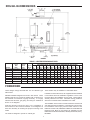
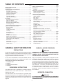
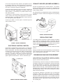
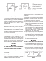
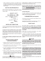
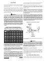
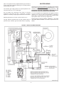
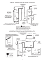
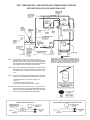
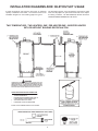
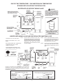
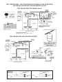
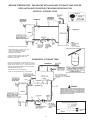
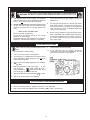
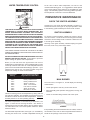
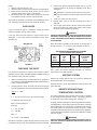
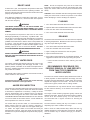
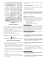
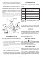
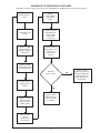
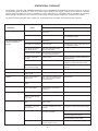
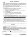


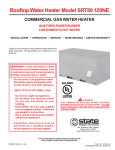


![Kenwood Z910DVD[K] Car Video System User Manual](http://vs1.manualzilla.com/store/data/007276303_1-7fde4030df8b82361c1715d4ef433389-150x150.png)