1
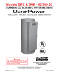
MODELS DEN AND DEL
COMMERCIAL ELECTRIC WATER HEATERS
• Installation
• Operation
• Electrical
• Maintenance
• Wiring Diagrams
• Replacement Parts
• Leakage Checkpoints • Limited Warranty
A DIVISION OF A. O. SMITH CORPORATION
McBee, South Carolina, USA
www.hotwater.com
CAUTION
TEXT PRINTED OR OUTLINED IN RED CONTAINS INFORMATION RELATIVE TO YOUR SAFETY.
PLEASE READ THOROUGHLY BEFORE INSTALLING AND USING THIS APPLIANCE.
PLACE THESE INSTRUCTIONS ADJACENT TO HEATER AND NOTIFY OWNER TO KEEP FOR FUTURE REFERENCE.
Printed in U.S.A. 0704
PART NO. 195201-000
1
ROUGH-IN DIMENSIONS
* NO SIDE OUTLET AVAILABLE
FOR DEL 6 MODELS
ROUGH-IN DIMENSIONS
Models
Dimensions
DEL-6
DEL-10
DEL-15
DEL-20
DEL-30
DEL-40
DEL-50
DEN-30
DEN-40
DEN-52
DEN-66
DEN-80
DEN-120
No. of
Elements
1
1
1
1
2
2
2
1
2
2
2
2
2
Tank Capacity
US Gals. Litres
6
23
10
38
15
57
20
76
30
114
40
151
50
189
30
114
40
151
50
189
66
250
80
303
119
450
A
inches
15 1/2
18 1/4
26
22 1/4
30 7/8
32 1/4
32 1/4
34 1/2
45 1/8
54 7/8
60 3/4
59 3/8
62 7/16
B
mm
394
464
660
565
784
819
819
876
1146
1394
1543
1508
1586
inches
14 1/4
18
18
21 3/4
21 3/4
24
26 1/2
20 1/2
20 1/2
20 1/2
21 3/4
24
29 3/8
C
mm
362
457
457
552
552
610
673
521
521
521
552
610
746
inches
11
12 1/2
20 1/2
15 3/8
24 1/8
25 9/16
25 1/8
-
mm
279
318
521
391
613
649
638
-
D
inches
8
8
8
8
8
8
8
8
8
Approx.
Shipping Weight.
Lbs.
Kg.
35
15.9
54
24.5
58
26.3
73
33.1
100
45.4
125
56.7
166
75.3
98
44.5
113
51.3
131
59.4
176
79.8
211
95.7
326
147.9
mm
203
203
203
203
203
203
203
203
203
RECOVERY CAPACITIES
Element
Wattage
(Upper/Lower)
INPUT
KW
F°
C°
NON-SIMULATANEOUS OPERATION
/1500
GPH
1.5
LPH
/2000
GPH
2.0
LPH
/2500
GPH
2.5
LPH
3000/3000
GPH
3.0
LPH
4000/4000
GPH
4.0
LPH
4500/4500
GPH
4.5
LPH
5000/5000
GPH
5.0
LPH
6000/6000
GPH
6.0
LPH
SIMULATANEOUS OPERATION
3000/3000
GPH
6
LPH
4000/4000
GPH
8
LPH
4500/4500
GPH
9
LPH
5000/5000
GPH
10
LPH
6000/6000
GPH
12
LPH
U.S. Gallons/Hr and Litres/Hr at TEMPERATURE RISE INDICATED
54F°
60F°
72F°
80F°
90F°
100F° 108F° 120F° 126F°
30C° 33.3C° 40C° 44.4C° 50C°
55.5C° 60C° 66.6C° 70C°
36F°
20C°
40F°
22.2C°
17
64
23
85
28
107
34
128
45
170
51
192
56
213
68
256
15
58
20
77
25
96
30
115
41
153
46
173
51
192
61
230
11
43
15
57
19
71
23
85
30
114
34
128
38
142
45
170
10
38
14
51
17
64
20
77
27
102
30
115
34
128
41
153
8
32
11
43
14
53
17
64
23
85
25
96
28
107
34
128
8
29
10
38
13
48
15
58
20
77
23
86
25
96
30
115
7
26
9
34
11
43
14
51
18
68
20
77
23
85
27
102
6
23
8
31
10
38
12
46
16
61
18
69
20
77
24
92
6
21
8
28
9
36
11
43
15
57
17
64
19
71
23
85
5
19
7
26
8
32
10
38
14
51
15
58
17
64
20
77
5
18
6
24
8
30
10
37
13
49
14
55
16
61
19
73
68
256
90
341
101
384
113
426
135
511
61
230
81
307
91
345
101
384
122
460
45
170
60
227
68
256
75
284
90
341
41
153
54
205
61
230
68
256
81
307
34
128
45
170
51
192
56
213
68
256
30
115
41
153
46
173
51
192
61
230
27
102
36
136
41
153
45
170
54
205
24
92
32
123
36
138
41
153
49
184
23
85
30
114
34
128
38
142
45
170
20
77
27
102
30
115
34
128
41
153
19
73
26
97
29
110
32
122
39
146
Recovery capacities at 100° F rise equal: for non-simultaneous element operation = 4.1 gal. x KW of one element; for simultaneous element operation
= 4.1 gal. x 2/3 KW of both elements. For other rises multiply element KW as previously explained by 410 and divide by temperature rise. Full load current for single
phase = total watts : voltage.
2
FOREWORD
• Do obtain new labels from A. O. Smith for placement on the
blanket directly over the existing labels.
Thank you for buying this energy efficient water heater from
A.O. Smith Water Products Company. We appreciate your
confidence in our products. Detailed installation diagrams are
in this manual. These diagrams will serve to provide the installer
with a reference for the materials and method of piping
suggested. IT IS NECESSARY THAT ALL WATER PIPING AND
THE ELECTRICAL WIRING BE INSTALLED AND CONNECTED
AS SHOWN IN THE DIAGRAMS.
EXTENDED NON-USE PERIODS
CAUTION
HYDROGEN GAS CAN BE PRODUCED IN A HOT WATER
SYSTEM SERVED BY THIS HEATER THAT HAS NOT BEEN USED
FOR A LONG PERIOD OF TIME (GENERALLY TWO WEEKS OR
MORE). HYDROGEN GAS IS EXTREMELY FLAMMABLE. To
reduce the risk of injury under these conditions, it is
recommended that the hot water faucet be opened for several
minutes at a nearby kitchen sink before using any electrical
appliance connected to the hot water system. If hydrogen is
present, there will probably be an unusual sound such as air
escaping through the pipe as the water begins to flow. THERE
SHOULD BE NO SMOKING OR OPEN FLAME NEAR THE
FAUCET AT THE TIME IT IS OPENED.
In addition to these instructions, the equipment shall be installed
in accordance with those installation regulations in force in the
local area where the installation is to be made. Authorities having
jurisdiction shall be consulted before installations are made.
GENERAL SAFETY
INSTRUCTIONS
CAUTION
BE SURE TO TURN OFF POWER WHEN WORKING ON OR
NEAR THE ELECTRICAL SYSTEM OF THE HEATER. NEVER
TOUCH ELECTRICAL COMPONENTS WITH WET HANDS OR
WHEN STANDING IN WATER. WHEN REPLACING FUSES
ALWAYS USE THE CORRECT SIZE FOR THE CIRCUIT.
AN ELECTRICAL GROUND IS REQUIRED TO REDUCE RISK
OF ELECTRIC SHOCK OR POSSIBLE ELECTROCUTION. THE
GROUND SCREW AT THE JUNCTION BOX IS FOR BONDING
THE HEATER TO A GROUNDED SERVICE ENTRANCE
CONDUCTOR, A GROUNDED SERVICE ENTRANCE RACEWAY,
OR AN EARTH GROUNDING ELECTRODE CONDUCTOR.
The principal components of the heater are identified on page 5.
The model and rating plate on page 6 interprets certain markings
into useful information. Both of these references should be
used to identify the heater, its components and optional
equipment.
WARNING
FAILURE TO FOLLOW THESE INSTRUCTIONS CAN RESULT
IN SERIOUS PERSONAL INJURY OR DEATH.
REQUIRED ABILITY
WARNING
FOR CALIFORNIA INSTALLATION THIS WATER HEATER MUST
BE BRACED, ANCHORED, OR STRAPPED TO AVOID FALLING
OR MOVING DURING AN EARTHQUAKE. SEE INSTRUCTIONS
FOR
CORRECT
INSTALLATION
PROCEDURES.
INSTRUCTIONS MAY BE OBTAINED FROM YOUR LOCAL
DEALER, WHOLESALER, PUBLIC UTILITIES OR CALIFORNIA’S
OFFICE OF STATE ARCHITECT, 400 P STREET, SACRAMENTO,
CA 95814.
INSTALLATION OR SERVICE OF THIS WATER HEATER
REQUIRES ABILITY EQUIVALENT TO THAT OF A LICENSED
TRADESMAN IN THE FIELD INVOLVED. PLUMBING AND
ELECTRICAL WORK ARE REQUIRED.
GENERAL
The installation must conform to these instructions, the local
code authority having jurisdiction, and the requirements of the
power company. In the absence of code requirements follow
the latest edition of NFPA-70, The National Electrical Code which
may be ordered from: National Fire Protection Association,
1 Batterymarch Park, Quincy, MA 02269.
INSULATION BLANKETS
Insulation blankets available to the general public for external
use on electric water heaters are not approved for use on your
A.O. Smith water heater. The purpose of an insulation blanket is
to reduce the standby heat loss encountered with storage tank
water heaters. Your A. O. Smith water heater meets or exceeds
the National Appliance Energy Act standards with respect to
insulation and standby loss requirements, making an insulation
blanket unnecessary.
LOCATION
The water heater should be located as close as possible to/or
centralized to the water piping system. The water heater should
be located in an area not subject to freezing temperatures.
The heater should be located in an area where leakage of the
tank or connections will not result in damage to the area adjacent
to the heater or to lower floors of the structure.
WARNING
Should you choose to apply an insulation blanket to this heater,
you should follow these instructions (See page 5 for identification
of components mentioned below). Failure to follow these
instructions can result in fire, asphyxiation, serious personal
injury or death.
When such locations cannot be avoided, a suitable drain pan
should be installed under the heater.
Such pans should be at least two inches deep, have a minimum
length and width of at least two inches greater than the diameter
of the heater and should be piped to an adequate drain.
• Do not cover the temperature & pressure relief valve.
Drain pans suitable for these heaters are available from your
distributor or A. O. Smith Products Service Division,
5621 W. 115th Street, Alsip, IL 60803.
• Do not cover the instruction manual. Keep it on the side of
the water heater or nearby for future reference.
3
CLEARANCES
CALCULATING
AMPERAGE/OVERCURRENT PROTECTION
A minimum clearance of 4” must be allowed for access to
replaceable parts such as the thermostats, drain valve and relief
valve.
The heaters come from the factory in two configurations:
1. Two wire C-2 circuit for single element heater equipped with
a high limit control, single phase power input.
Adequate clearance for servicing this appliance should be
considered before installation, such as changing the anodes,
etc.
2. Four wire A-8 circuit for dual element heater equipped with
two high limit controls, single phase or three phase power
input.
FLOOD WARNING
IF THE HEATER BECOMES IMMERSED IN WATER UP TO OR
ABOVE THE LEVEL OF THE BOTTOM OF THE ELEMENT
DOORS, THE HEATER SHOULD BE EXAMINED BY A
COMPETENT SERVICE PERSON BEFORE IT IS PLACED IN
OPERATION.
The heater with dual elements is factory wired for connection to
a three wire, three-phase delta branch circuit, non-simultaneous
operation. In addition a ground conductor is required.
Element connection is for non-simultaneous operation. This
means only one element at a time operates. The wiring diagram
(on page 5) shows the heater may be field converted to
simultaneous element operation by moving the red wire on
“J” terminal to L1. It is then possible for both elements to operate
at once as determined by the thermostats. Regardless of
element connection the heater operates in an “unbalanced”
fashion.
CHEMICAL VAPOR CORROSION
Water heater corrosion and component failure can be caused by
the heating and breakdown of airborne chemical vapors. Spray
can propellants, cleaning solvents, refrigerator and air
conditioning refrigerants, swimming pool chemicals, calcium
and sodium chloride, waxes, and process chemicals are typical
compounds which are potentially corrosive. These materials
are corrosive at very low concentration levels with little or no odor
to reveal their presence.
The heater may be field converted to single-phase operation by
moving the wire on L3 of the terminal block to L2. L3 is not
used. (See page 5).
Products of this sort should not be stored near the heater. Also,
air which is brought in contact with the water heater should not
contain any of these chemicals. If necessary, uncontaminated
air should be obtained from remote or outside sources.
The heater, now in single-phase non-simultaneous operation,
may be field-converted to single phase simultaneous operation
by moving the red wire on terminal “J” to L1, refer to wiring
diagram on page 5.
ELECTRICAL (GENERAL)
This is an example of calculating heater amperage for both
types of element operation. From this, the branch circuit
conductor and overcurrent protection sizing can be established.
Check the heater model and rating plate information against the
characteristics of the branch circuit electrical supply. DO NOT
CONNECT THE HEATER TO AN IMPROPER SOURCE OF
ELECTRICITY. Contact the heater supplier for conversion
information if necessary.
The example is of a three-phase 240 volt unit with two, 6 kw
elements. The notations are for units field converted to
single-phase. Check the heater model and rating plate for actual
specifications and substitute those values in the following.
Voltage applied to the heater should not vary more than +5%
to -10% of the model and rating plate marking for satisfactory
operation.
DO NOT ENERGIZE THE BRANCH CIRCUIT FOR ANY REASON
BEFORE THE HEATER TANK IS FILLED WITH WATER. DOING
SO WILL CAUSE THE HEATING ELEMENTS TO BURN OUT.
The factory wiring is attached to a terminal block within external
junction box unit. The branch circuit is connected to terminal
block within this junction box. The water heater should be
connected to a separate, grounded, branch circuit with overcurrent
protection and disconnect switch. The water heater should be
grounded in accordance with national and local codes.
Non-simultaneous:
(as factory wired)
Simultaneous:
(Field conversion)
3000 : 240 = 12.5 amps*
3000 : 240 = 12.5 amps*
12.5 x 1.73 = 21.6 amps
*NOTE: as a single-phase
non-simultaneous unit.
*NOTE: as a single-phase
simultaneous unit the
total is:
12.5 x 2 = 25 amps
The rating of the overcurrent protection should be computed on
the basis of 125 percent of the total connected load amperage.
Where the standard ratings and settings do not correspond
with this computation, the next higher standard rating or setting
should be selected.
BRANCH CIRCUIT
The branch circuit wire size should be established through
reference to the latest edition of NFPA-70, the
National Electrical Code or other locally approved source in
conjunction with the heater amperage rating. For convenience,
portions of the wire size tables from the Code are reproduced
here. It is suggested the electrician size the branch circuit at 125
percent of the heater rating and further increase wire size as
necessary to compensate for voltage drop in long runs.
Portion of Table 310-16 follows:
Allowable Ampacities of Insulated Copper Conductors. Not
more than three conductors in Raceway or Cable or Direct Burial
(Based on Ambient Temperature of 30° C, 86° F).
These ampacities relate only to conductors described in Table
310-13 in Code.
4
For ambient temperatures over 30° C (86° F), see Correction
Factors, Note 13 in Code.
Size
AMG
MCM
18
16
14
12
10
8
6
4
3
Not more than three conductors in Raceway or Cable or Direct
Burial (Based on Ambient Temperature of 30° C, 86° F. These
ampacities relate only to conductors described in Table 310-13
in Code.
Temperature Rating of Conductor
See Table 310-13 in Code
60° C
75° C
(140° F)
(167° F)
TYPES:
TYPES:
RUW
RH, RHW, RUH,
(14-2),
(14-2), THW
T, TW,
THWN, XHHW,
UF
USE
--------15
15
20
20
30
30
40
45
55
65
70
85
80
100
For ambient temperatures over 30° C (86° F), see Correction
Factors, Note 13 in Code.
Size
AMG
MCM
12
10
8
6
4
3
2
1
Portion of Table 310-18 follows:
Allowable Ampacities of Insulated Aluminum and Copper -Clad
Aluminum Conductors.
Temperature Rating of Conductor
See Table 310-13 in Code
60° C
75° C
(140° F)
(167° F)
TYPES:
TYPES:
RUW
RH, RHW, RUH,
(12-2),
(12-2), THW
T, TW,
THWN, XHHW,
UF
USE
15
15
25
25
30
40
40
50
55
65
65
75
75
90
85
100
WIRING DIAGRAMS
A-8 CIRCUIT FOR DUAL ELEMENT HEATER
C-2 CIRCUIT
FOR SINGLE
ELEMENT HEATERS
EQUIPPED WITH HIGH
LIMIT CONTROL
FACTORY WIRED
---------- FIELD WIRING
† WHITE FOR 120V
5
TYPICAL PIPING CONNECTIONS
This page shows typical water heater installations by model designations.
DUAL ELEMENTS HEATER
SINGLE ELEMENT HEATER
INSTALL SUITABLE DRAIN PANS UNDER HEATERS TO
PREVENT DAMAGE DUE TO LEAKAGE. REFER TO WATER
HEATER LOCATION ON PAGE 2.
INSTALL THERMAL
EXPANSION TANK IF
CHECK VALVE OR
PRESSURE REDUCING
VALVE IS USED IN
SUPPLY LINE.
INSTALL VACUUM RELIEF
IN COLD WATER INLET
LINE AS REQUIRED BY
LOCAL CODES.
† OVER CURRENT PROTECTION MUST BE SUPPLIED IN WATER HEATER CIRCUIT.
CONSULT LOCAL CODE OR NEC-1984 FOR PROPER INSTALLATION.
* INSTALL IN ACCORDANCE WITH ALL LOCAL CODES.
that any discharge from the valve will exit only within 6 inches
above, or at any distance below, the structural floor and cannot
contact any live electrical part. THE DISCHARGE OPENING
MUST NOT BE BLOCKED OR REDUCED IN SIZE UNDER ANY
CIRCUMSTANCES.
TEMPERATURE AND PRESSURE RELIEF VALVE
CAUTION
TO REDUCE THE RISK OF EXCESSIVE PRESSURES AND
TEMPERATURES IN THIS WATER HEATER, INSTALL
TEMPERATURE AND PRESSURE PROTECTIVE EQUIPMENT
REQUIRED BY LOCAL CODES BUT NOT LESS THAN A
COMBINATION TEMPERATURE AND PRESSURE RELIEF
VALVE CERTIFIED BY A NATIONALLY RECOGNIZED TESTING
LABORATORY THAT MAINTAINS PERIODIC INSPECTION OF
PRODUCTION OF LISTED EQUIPMENT OR MATERIALS, AS
MEETING THE REQUIREMENTS FOR RELIEF VALVE DEVICES
FOR HOT WATER SUPPLY SYSTEMS. (ANSI Z21.22.)
DUAL ELEMENT
RATING PLATE
This valve must be marked with a maximum set pressure not to
exceed the marked maximum working pressure of the water
heater. Install the valve into an opening provided and marked for
this purpose in the water heater, and orient it or provide tubing so
6
SINGLE ELEMENT
RATING PLATE
Figure 3 shows the approximate time-to-burn relationship for
normal adult skin. The thermostats on your water heater have a
linear relationship between degrees of angular rotation and the
corresponding change in temperature. Thus rotating the
temperature adjustment indicator 30 angular degrees will result
in a 10 degree Fahrenheit change in water temperature.
OPERATION
CAUTION
DO NOT OPERATE THE HEATER WITHOUT INSTALLING AN
APPROVED TEMPERATURE AND PRESSURE RELIEF VALVE
IN THE OPENING PROVIDED IN THE TANK. GROUND THE
HEATER TO GUARD AGAINST ELECTRIC SHOCK FROM THE
HEATER OR WATER SYSTEM. NEVER OPERATE THE HEATER
WITHOUT FILLING WITH WATER PER THE FILLING
INSTRUCTIONS. FAILURE TO DO SO WILL DAMAGE INTERNAL
PARTS.
FILLING
1. Close the water heater drain valve by turning hand-wheel to
right (clockwise).
Temperature
Time to Produce 2nd & 3rd
Setting
Degree Burns on Adult Skin
180° F (82° C)
160° F (71° C)
150° F (66° C)
140° F (60° C)
130° F (54° C)
125° F ( 52° C)
120° F (49° C)
Nearly instantaneous
About 1/2 second
About 1-1/2 seconds
Less than 5 seconds
About 30 seconds
About 2 minutes
More than 5 minutes
2. Open a nearby hot water faucet to permit the air in the system
to escape.
FIGURE 3
TEMPERATURE ADJUSTMENT
3. Fully open the cold water inlet valve allowing the heater and
piping to be filled.
The water temperature is controlled by surface mounted
thermostats with hi-limit. There is one mounted firmly against
the tank directly above each element. The thermostats of A-8
circuit are adjustable from approximately 120°F (49°C) (lowest
setting) to 180°F (82°C) (highest setting). The thermostat of C-2
circuit is adjustable from approximately 110°F (43°C) to 170°F
(77°C) with a factory set point 120°F (49°C). The over temperature
device (hi-limit) attached to each thermostat has a manual reset.
4. Close the hot water faucet as water starts to flow.
5. Turn on the electrical switch to the water heater.
WARNING
DO NOT ATTEMPT TO OPERATE HEATER WITH COLD WATER
INLET VALVE CLOSED.
TEMPERATURE REGULATION
ADJUSTABLE UPPER
THERMOSTAT BEHIND
JUNCTION BOX DOOR
DANGER
THE WATER HEATER IS EQUIPPED WITH AN ADJUSTABLE
THERMOSTAT TO CONTROL WATER TEMPERATURE. HOT
WATER AT TEMPERATURES DESIRED FOR AUTOMATIC
DISHWASHER AND LAUNDRY USE CAN CAUSE SCALDS
RESULTING IN SERIOUS PERSONAL INJURY AND/OR DEATH.
THE TEMPERATURE AT WHICH INJURY OCCURS VARIES WITH
THE PERSON’S AGE AND TIME OF EXPOSURE. THE SLOWER
RESPONSE TIME OF CHILDREN , AGED OR DISABLED
PERSONS INCREASES THE HAZARD TO THEM. NEVER ALLOW
SMALL CHILDREN TO USE A HOT WATER TAP, OR TO DRAW
THEIR OWN BATH WATER. NEVER LEAVE A CHILD OR
DISABLED PERSON UNATTENDED IN A BATHTUB OR
SHOWER.
DANGER
1. Turn off the heater electrical supply. Do not attempt to adjust
thermostat with power on.
It is recommended that lower water temperatures be used to
avoid the risk of scalding. It is further recommended, in all cases,
that the water temperature thermostats (See Figure 3) be set for
the lowest temperature which satisfies your hot water needs.
This will also provide the most energy efficient operation of the
water heater.
2. Open the junction box door (for upper thermostat of dual
element water heater only) and/or remove the (lower)
thermostat access panel. Do not remove the plastic personel
protectors covering the thermostats. The thermostat is factory
pre-set at 140°F (60°C) for dual element units or at 120°F
(49°C) for single element units.
ADJUSTABLE
LOWER (SINGLE)
THERMOSTAT
FIGURE 4
NOTE: It is not necessary to adjust the upper thermostat for a
dual element unit. However, if it is adjusted above the factory set
point 140°F (60°C) it is recommended that it not be set higher
than the lower thermostat setting.
To change the temperature setting:
7
3. Using a flat tip screwdriver, rotate the adjusting knob to the
desired temperature setting.
Once a month the temperature and pressure relief valve should
be checked to ensure that it is in operating condition. Lift the
lever on the valve several times until the valve seats properly and
operates freely.
4. Replace the covers and access panels, and turn on heater
electrical supply.
CAUTION
THE WATER PASSING OUT OF THE VALVE DURING THIS
CHECKING OPERATION MAY BE EXTREMELY HOT.
Valves for reducing point-of-use temperature by mixing cold and
hot water are available (See Figure 5). Also available are
inexpensive devices that attach to faucets to limit hot water
temperatures. Contact a licensed plumber or the local plumbing
authority.
It is recommended that the drain valve on this unit be opened
once a month and 1 to 2 gallons of water be allowed to drain out.
This will help to prevent sediment buildup in the tank bottom.
A non-adjustable high temperature limit control operates before
steam temperatures are reached. The high limit is in the same
area as the upper thermostat and must be reset manually when
it operates. BECAUSE THE HIGH LIMIT OPERATES ONLY
WHEN ABNORMALLY HIGH WATER TEMPERATURES ARE
PRESENT, IT IS IMPORTANT THAT A QUALIFIED SERVICE
AGENT BE CONTACTED TO DETERMINE THE REASON FOR
OPERATION BEFORE RESETTING.
ANODE ROD MAINTENANCE
The anode rod is used to protect the tank from corrosion. Most
hot water tanks are equipped with an anode rod. The submerged
rod sacrifices itself to protect the tank. Instead of corroding the
tank, water ions attack and eat away the anode rod. This does
not affect the water's taste or color. The rod must be maintained
to keep the tank in operating condition. Failure to inspect and/or
replace the anode rod will result in voiding the warranty.
Anode deterioration depends on water conductivity, not
necessarily water condition. It may be necessary to have the
anode rod inspected a few times during the first year to see what
effect the water has had. A corroded or pitted anode rod, in the
first year, indicates high water conductivity and should be checked
and or replaced more often than an anode rod that appears to
be fairly clean. Inspection should be conducted by a qualified
technician.
REPLACEMENT PARTS
FIGURE 5
Replacement parts may be ordered through dealers, authorized
servicers or distributors. Refer to Yellow Pages for where to call
or contact the Product Service Division, 5621 W. 115th Street,
Alsip, IL 60803, 1-800-433-2545. When ordering parts, specify
complete model number, serial number, (see rating plate),
quantity and name of part desired. Standard hardware items
should be purchased locally.
DRAINING
If the heater is to be shut down and exposed to freezing
temperatures, it must be drained. Water, if left in the tank and
allowed to freeze, will expand and damage the heater.
1. Turn off the electrical switch and cold water inlet valve.
•
If desired, a hose may be connected to the drain valve
to carry the water away.
TROUBLESHOOTING
CHECKLIST
2. Open a nearby hot water faucet and the heater drain
valve.
•
Before contacting your dealer, check the water heater to see if
the apparent malfunction is caused by some external fault.
Consulting this checklist may eliminate the need for a repair call
and restore hot water service.
Be careful to grasp the drain valve handle in such a
way that the hand will not be exposed to hot water.
3. The drain valve must be left open during the shutdown
period.
•
NOT ENOUGH OR NO HOT WATER
To restart heater, refer to the foregoing FILLING
instructions.
1. Be certain that the water heater electrical switch is turned to
the ON position.
MAINTENANCE
•
Electric water heater maintenance consists of cleaning the tank
and removing lime (or scale) from the heating elements in hard
water areas. Tank flushing should be performed monthly. Tank
sediment removal and element lime scale removal must be
performed when needed as determined by periodic inspections.
Your dealer should be contacted for element cleaning. In some
instances a hissing sound may be heard as the scale builds up.
This noise is normal.
In some areas an additional special meter, controlled
by a timer, is used to govern the periods electricity is
available. If the heater operates on a timed electrical
circuit, recovery will be limited to certain hours.
2. Check for loose or blown fuses in the water heater circuit.
3. If the water has been excessively hot and is now cold, the high
temperature limit control may have operated. To restore
8
service, contact your dealer or utility company. Refer to
TEMPERATURE REGULATION section.
4. The storage capacity of the heater may have been exceeded
by large demands of hot water.
•
Excessive water temperature.
•
Faulty relief valve.
Excessive water pressure is the most common cause of relief
valve leakage. It is often caused by a “closed system”. A check
valve in the inlet system will not permit the expanded hot water
volume to equalize pressure with the main. A relief valve must
release this water or the water heater or plumbing system will
be damaged.
When such a condition is encountered, local codes or inspection
agency should be consulted to determine which system is
acceptable in your area. These may consist of:
5. If the heater was installed when incoming water temperatures
were warm, colder incoming temperatures will create the
effect of less hot water.
6. Look for leaking or open hot water faucets.
WATER IS TOO HOT
1. Refer to TEMPERATURE REGULATION section.
•
Installation of a second relief valve with lower setting
than the primary safety relief valve.
•
An expansion tank of suitable pressure and provision
to avoid water logging.
•
Removal of the check valve.
WATER HEATER MAKES SOUNDS
1. See MAINTENANCE
WATER LEAKAGE IS SUSPECTED
IF YOU CANNOT IDENTIFY OR CORRECT
THE SOURCE OF THE MALFUNCTION
1. Check to see if the heater drain valve is tightly closed.
2. The apparent leakage may be condensation which forms on
cool surfaces of the heater and piping.
1. Place the water heater electrical switch in the OFF position.
3. If the outlet of the relief valve is leaking it may represent:
2. Close the cold water inlet valve to the heater.
•
Excessive water pressure.
3. Contact your dealer.
NOTES
9
LEAKAGE CHECKPOINTS
Instructions: Use this illustration as a guide when checking for sources of water leakage. You or your dealer may be able to correct what
appears to be a problem. NOTE: Cover and Insulation shown removed to reveal tank top
Where possible remove or lift top cover to
examine threads of fittings installed into tank
for evidence of leakage. Correct fitting leaks
as necessary.
Relief Valve
To Open Drain
Condensation and dripping may appear on
pipes when cold water temperature is low.
Pipe fitting may be leaking.
Water leaks at the elements may be due to:
1. Defective element which leaks at terminals
or thru flange. Replace element*.
Anode Rod (Some Models)
2. Loose element/gasket leak:
(a)
Screw-in type: tighten with
1-1/2” socket wrench or Part Number 23985
wrench.
If leak continues, remove
element*, discard gasket and clean thread
areas.Apply
nonhardeningPermatex
Number 2 to thread areas, install new
gasket and screw element into fitting until
it seats. Tighten 1/2 to 3/4 turn with wrench.
Relief valve operation and leakage may be
due to water expansion during heating cycle
or foreign material on seat of valve. If the
valve is not piped to an open drain the
released water could be mistaken for a
leaking heater. To check where threaded
material between jacket opening and swab
spud area, remove valve* if indicated and
repair with pipe joint compound.
To Open Drain
(b) Flange type: tighten screw with wrench.
If leak continues remove element* and
discard gasket. Clean gasket seating
areas and re-install element with new
gasket. NOTE: Part Number 40000-1 scale
cleaning replacement screws available
where threads have become rusted or
damaged, preventing tightening.
Water on the side of the tank may be
condensation due to the panel or insulation
not being in place.
All water which appears at the heater bottom
or on the surrounding floor may be caused by
condensation, loose connections or relief
valve operation and leakage. Do not replace
the heater until full inspection of all potential
leak points is made and corrective steps taken
to stop the leak. Leakage from other
appliances, water lines or ground seepage
should also be suspected until proven
otherwise.
Drain valve leakage could be from the valve
itself.* To check for leakage where threaded
portion enters tank, insert Q-tip or similar
absorbent material between jacket opening
and valve to swab spud area. Remove
valve* if leak is indicated and repair with
pipe joint compound.
*Contact your dealer as it is necessary to shut off
electricity and drain tank to perform procedure.
10
MODELS DEN AND DEL ELECTRIC WATER HEATER LIMITED WARRANTY
A. 0. Smith Corporation, the warrantor, extends the following LIMITED WARRANTY to the owner of this water heater:
1. THE TANK
If the glass-Iined tank in this water heater shall prove upon examination by the warrantor to have leaked due to natural corrosion from potable
water therein, during the first THREE years after initial installation, the warrantor will supply a complete new A. 0. Smith water heater of
equivalent size and current model. Some government agencies are requiring energy efficient standards for water heaters. In the event
regulations prohibit sale of a model of equivalent size and construction, A. 0. Smith will provide a model which complies with the regulations
of your area, in which case the consumer will be charged the difference in price between the like replacement and the energy efficient model
required. The warranty on the replacement water heater will be limited to the unexpired term of the original warranty.
2. ALL OTHER PARTS
If within ONE year after initial installation of this water heater, any part or portion shall prove upon examination by the warrantor to be defective
in material or workmanship, the warrantor will repair or replace such part or portion at its option.
3. CONDITIONS and EXCEPTIONS
This warranty shall apply only when the water heater is installed in accordance with local plumbing and building codes, ordinances and
regulations, the printed instructions provided with it and good industry practices. In addition, a temperature and pressure relief valve, certified
by A. G. A. and approved by the American Society of Mechanical Engineers, must have been installed.
a. This warranty shall apply only when the heater is:
(1) used at temperatures not exceeding the maximum calibrated setting of its thermostat;
(2) used at water pressure not exceeding the working pressure shown on the heater;
(3) filled with potable water, free to circulate at all times and with the tank free of damaging water sediment or scale deposits;
(4) used in a non-corrosive and non-contaminated atmosphere;
(5) used with factory approved anode(s) installed;
(6) in its original installation location;
(7) in the United States, its territories or possessions, and Canada;
(8) sized in accordance with proper sizing techniques for commercial water heaters;
(9) bearing a rating plate which has not been altered, defaced or removed, except as required by the warrantor;
(10) used in an open system or in a closed system with properly sized and installed thermal expansion tank;
(11) fired at the proper voltage and wattage as stated on the rating plate;
(12) maintained in accordance with the instructions printed in the manual included with the heater.
b. Any accident to the water heater, any misuse, abuse (including freezing) or alteration of it, any operation of it in a modified form, or any
attempt to repair tank leaks will void this warranty.
4. SERVICE and REPAIR EXPENSE
Under this limited warranty the warrantor will provide only a replacement water heater or part thereof. The owner is responsible for all other
costs. Such costs may include but are not limited to:
a. Labor charges for service, removal, repair, or reinstallation of the water heater or any component part;
b. Shipping, delivery, handling, and administrative charges for forwarding the new heater or replacement part from the nearest
distributor and returning the claimed defective heater or part to such distributor;
c. All cost necessary or incidental for any materials and/or permits required for installation of the replacement heater or part.
5. LIMITATIONS ON IMPLIED WARRANTIES
Implied warranties, including any warranty of merchantability imposed on the sale of this heater under state law are limited to one (1) year
duration for the heater or any of its parts. Some states do not allow limitations on how long an implied warranty lasts, so the above limitation
may not apply to you.
6. CLAIM PROCEDURE
Any claim under this warranty should be initiated with the dealer who sold the heater, or with any other dealer handling the
warrantor’s products. If this is not practicable, the owner should contact:
U.S. Customers
Canadian Customers
A. 0. Smith Water Products Company
A. 0. Smith Enterprises, Ltd.
5621 W 115th Street
P. 0. Box 310- 768 Erie Street
Alsip, IL 60803
Stratford, Ontario N5A 6T3
Telephone: 1-800-323-2636
Telephone: 1-800-265-8520
a. The warrantor will only honor replacement with identical or similar water heater or parts thereof which are manufacture
or distributed by the warrantor.
b. Dealer replacements are made subject to in-warranty validation by warrantor.
7. DISCLAIMERS
NO OTHER EXPRESS WARRANTY HAS BEEN OR WILL BE MADE IN BEHALF OF THE WARRANTOR WITH RESPECT TO THE MERCHANTABILITY
OF THE HEATER OR THE INSTALLATION, OPERATION, REPAIR, OR REPLACEMENT OF THE HEATER. THE WARRANTOR SHALL NOT BE
RESPONSIBLE FOR WATER DAMAGE, LOSS OF USE OF THE UNIT, INCONVENIENCE, LOSS OR DAMAGE TO PERSONAL PROPERTY, OR
OTHER CONSEQUENTIAL DAMAGE. THE WARRANTOR SHALL NOT BE LIABLE BY VIRTUE OF THIS WARRANTY OR OTHERWISE FOR
DAMAGE TO ANY PERSONS OR PROPERTY, WHETHER DIRECT OR INDIRECT, AND WHETHER ARISING IN CONTRACT OR IN TORT.
a. Some states do not allow the exclusion or limitation of the incidental or consequential damage, so the above limitation or
exclusion may not apply to you.
b. This warranty gives you specific legal rights, and you may also have other rights which vary from state to state.
Fill in the following for your own reference. Keep it. Registration is not a condition of warranty. The model and serial number are found on
the heater’s rating plate.
Model No.
Serial No.
Date Installed
Dealer’s Name
Dealer’s Address
Phone No.
City and State
Zip
11
5621 W. 115TH STREET, ALSIP, IL 60803
Phone: 800-433-2545 Fax: 800-433-2515
www.hotwater.com e-mail: [email protected]
12