1
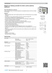
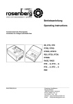
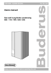
ADMP / ADM / ADMR
Atmospheric commercial
water heater
ADMP / ADM / ADMR - 40/50/60/80/90/115/135
An extensive range of atmospheric water heaters to suit most
larger hot water systems • Efficient, automatic hot surface igniter
• Removable control column for convenient servicing • Frostprotection thermostat • Stainless steel burner for natural or LP gas
• Two access covers for comprehensive waterside tank maintenance
• External control connection • Voltage-free contact for general
fault indication • Optional ancillaries: Unvented kits • Destratification
pump kit • Powered anode • Flue fan kit • ADMP Permanent pilot
ignition • Pilot proving kit available • ADM Electronic ignition
• Control, high limit and energy cut-off thermostats provide triple
protection and ensure safe operation • ADMR Electronic ignition
• Flue damper to minimise standing losses • ThermoControl for
easy and flexible control / fault diagnosis • Programmable for
legionella purge cycle
Innovation has a name.
ADMP / ADM / ADMR
ADMR 135
ADMR 115
ADMR 90
ADMR 80
ADMR 60
ADMR 50
ADMR 40
ADM 135
ADM 115
ADM 90
ADM 80
ADM 60
ADM 50
ADM 40
Technical specifications
Gas data natural gas 2H (G20)
Input*
Output
Inlet pressure
Burner pressure
Gas consumption**
Diameter main orifice
Max. flue gas temperature
Flue gas discharge
kW
kW
mbar
mbar
m3/h
mm
°C
kg/h
42.2 56.5 66.4 82.5 98.3 126.6 143.4 42.2 56.5 66.4 82.5 98.3 126.6 143.4
32.3 42.8 50.2 62.4 74.3 95.8 109.8 32.3 42.8 50.2 62.4 74.3 95.8 109.8
20
20
20
20
20
20
20
20
20
20
20
20
20
20
8.5
8.5
8.5
8.5
8.5
8.5 11.3
8.5
8.5
8.5
8.5
8.5
8.5 11.3
4.0
5.4
6.3
7.9
9.4 12.1 13.7
4.0
5.4
6.3
7.9
9.4 12.1 13.7
3.2
3.2
3.1 2.95
3.2
3.2
3.9
3.2
3.2
3.1 2.95
3.2
3.2
3.9
180
200
200
180
180
200
185
180
200
200
180
180
200
185
121.7 130.2 199.4 190.1 329.0 253.1 302.6 121.7 130.2 199.4 190.1 329.0 253.1 302.6
kW
kW
mbar
mbar
kg/h
mm
°C
kg/h
41.6 55.3 68.2 80.7 96.1 123.5 138.4 41.6 55.3 68.2 80.7 96.1 123.5 138.4
32.6 42.8 52.8 62.6 74.5 95.8 108.5 32.6 42.8 52.8 62.6 74.5 95.8 108.5
30
30
30
30
30
30
30
30
30
30
30
30
30
30
-
-
-
-
-
-
-
-
-
-
-
-
-
3.0
4.0
5.0
5.9
7.0
9.0 10.1
3.0
4.0
5.0
5.9
7.0
9.0 10.1
1.7
1.7
1.7
1.5
1.7
1.7 2.25
1.7
1.7
1.7
1.5
1.7
1.7 2.25
180
200
200
180
180
200
185
180
200
200
180
180
200
185
125.9 129.4 183.9 205.3 344.9 255.6 319.6 125.9 129.4 183.9 205.3 344.9 255.6 319.6
kW
kW
mbar
mbar
kg/h
mm
°C
kg/h
38.4 51.1 63.3 77.7 89.6 113.0 130.1 38.4 51.1 63.3 77.7 89.6 113.0 130.1
30.0 39.5 48.9 60.1 69.2 87.4 101.7 30.0 39.5 48.9 60.1 69.2 87.4 101.7
37
37
37
37
37
37
37
37
37
37
37
37
37
37
-
-
-
-
-
-
-
-
-
-
-
-
-
2.7
3.7
4.5
5.6
6.4
8.1
9.3
2.7
3.7
4.5
5.6
6.4
8.1
9.3
1.7
1.7
1.7
1.5
1.7
1.7 2.25
1.7
1.7
1.7
1.5
1.7
1.7 2.25
180
200
200
180
180
200
185
180
200
200
180
180
200
185
115.2 119.9 177.5 187.4 187.4 239.4 297.1 115.2 119.9 177.5 187.4 187.4 239.4 297.1
l
°C
l
l
l
l
l/h
min.
l
l
l
l
l/h
min.
l
l
l
l
l/h
min.
309
73
621
937
1253
1568
631
29
547
824
1102
1380
556
33
497
749
1002
1255
505
37
Gas data butane 3+ (G30)
Input*
Output
Inlet pressure
Burner pressure
Gas consumption**
Diameter main orifice
Max. flue gas temperature
Flue gas discharge
Gas data propane 3+ (G31)
Input*
Output
Inlet pressure
Burner pressure
Gas consumption**
Diameter main orifice
Max. flue gas temperature
Flue gas discharge
Draw-off capacity
Storage capacity
Max. temperature setting
30 min. ∆T=44°C
60 min. ∆T=44°C
90 min. ∆T=44°C
120 min. ∆T=44°C
Continuous ∆T=44°C
Heating-up time ∆T=44°C
30 min. ∆T=50°C
60 min. ∆T=50°C
90 min. ∆T=50°C
120 min. ∆T=50°C
Continuous ∆T=50°C
Heating-up time ∆T=50°C
30 min. ∆T=55°C
60 min. ∆T=55°C
90 min. ∆T=55°C
120 min. ∆T=55°C
Continuous ∆T=55°C
Heating-up time ∆T=55°C
357
73
766
1183
1601
2019
836
26
674
1041
1409
1777
735
29
612
947
1281
1615
669
32
298
73
767
1258
1749
2240
982
18
675
1107
1539
1971
864
21
614
1006
1399
1792
785
23
335
73
914
1524
2134
2744
1220
16
805
1341
1878
2415
1073
19
732
1219
1707
2195
976
21
278
73
957
1684
2410
3137
1453
11
842
1482
2121
2760
1279
13
766
1347
1928
2509
1162
14
253
73
1118
2054
2990
3926
1872
8
984
1808
2631
3455
1647
9
895
1643
2392
3141
1497
10
252
73
1240
2313
3385
4458
2145
7
1092
2035
2979
3923
1888
8
992
1850
2708
3566
1716
9
309
80
621
937
1253
1568
631
29
547
824
1102
1380
556
33
497
749
1002
1255
505
37
357
80
766
1183
1601
2019
836
26
674
1041
1409
1777
735
29
612
947
1281
1615
669
32
298
80
767
1258
1749
2240
982
18
675
1107
1539
1971
864
21
614
1006
1399
1792
785
23
335
80
914
1524
2134
2744
1220
16
805
1341
1878
2415
1073
19
732
1219
1707
2195
976
21
278
80
957
1684
2410
3137
1453
11
842
1482
2121
2760
1279
13
766
1347
1928
2509
1162
14
253
80
1118
2054
2990
3926
1872
8
984
1808
2631
3455
1647
9
895
1643
2392
3141
1497
10
252
80
1240
2313
3385
4458
2145
7
1092
2035
2979
3923
1888
8
992
1850
2708
3566
1716
9
W
30
30
30
30
30
30
60
50
50
50
50
50
50
VAC/Hz230 (-15 / +10%) / 50230 (-15 / +10%) / 50 (+/- 1 Hz)
80
Electrical data
Power consumption
Power supply
General
Anodes
-
2
2
2
3
3
4
4
2
2
2
Maximum working pressure
bar
8
Maximum weight
kg
504
578
507
573
522
523
581
504
578
507
3
3
4
4
8
573
522
523
581
Shipping data
Weight empty
Weight incl. packaging
Width packaging
Height packaging
Depth packaging
kg
kg
mm
mm
mm
* Gas data on gross value
**Gas consumption at 15°C and 1013.25 mbar
195
214
780
1930
870
221
242
780
2140
870
209
230
780
1930
870
238
259
780
2140
870
244
265
780
1975
870
270
291
780
2045
870
329
350
910
2050
910
195
214
780
1930
870
221
242
780
2140
870
209
230
780
1930
870
238
259
780
2140
870
244
265
780
1975
870
270
291
780
2045
870
329
350
910
2050
910
ADMP / ADM / ADMR
ADM(R) 40
ADM(R) 50
ADM(R) 60
ADM(R) 80
ADM(R) 90
ADM(R) 115
ADM(R) 135
Dimensions ADM / ADMR
A
B
D
E
F
G
H
J
K
M
N
P
R
S
1900
1760
710
800
1100
150
660
1840
400
565
1605
730
500
1550
2100
1960
710
800
1100
150
660
2040
400
565
1810
730
515
1760
1900
1760
710
800
1100
180
660
1840
400
565
1605
730
500
1550
2100
1960
710
800
1100
180
660
2040
400
565
1810
730
515
1760
2000
1795
710
800
1105
225
675
1935
400
575
1640
740
525
1595
2085
1870
710
800
1105
225
675
2010
400
650
1715
825
600
1660
2085
1870
710
800
1105
225
675
2010
205
650
1715
855
595
1660
1
2
3
4
5
Cold water (external)
Hot water (internal)
Gas control (internal)
Tank drain valve (internal)
T&P valve (internal)
6
Cleaning and inspection opening
R11/2
Rp11/2
Rp3/4 (ADM(R) 135 = Rp1)
Rp11/2
1-11.5 NPT (40-80)
Rp11/2 (90-135)
Ø100
Dimensions in mm. All ADM and ADMR water heaters receive
a three years warranty on the tank and one year on parts.
ADMP / ADM / ADMR
Installation diagrams ADM / ADMR
Vented
Unvented
1
3
4
5
6
7
9
10
11
12
14
15
16
17
18
19
Pressure reducing valve
T&P valve
Stop valve
Non-return valve
Circulation pump
Destratification pump
Drain valve
Gas cock
Isolating valve
Temperature gauge
Hot water outlets
Expansion relief valve
Expansion vessel
Three way valve
Water tank
Float valve
A
B
C
D
E
H
Cold water
Hot water
Return circulation
Gas supply
Overflow pipe
Expansion vent pipe
A.O. Smith unvented system kits utilise combination valves.
An ADM/ADMP or ADMR water heater should be installed
in accordance with local standards and ventilation requirements (category B11BS).
Further installation and connection details can be found in
the Installation & Commissioning Manual.
ADMP / ADM / ADMR
Electrical diagram ADM
TERMINAL STRIP CONNECTIONS
Earth
N
Neutral
L1 Phase input of controller
L2 Phase input of flue gas
thermostat
L3 Phase output of flue gas
thermostat
COMPONENTS
A
Two-terminal main switch
B
Flue gas thermostat
C
Indicator LED “Error”
D
Indicator LED “Running”
E
“RESET” button
F
Burner control
G
Control thermostat
H
Frost thermostat
J
0/1 switch of controller
K
Safety thermostat
L
High-limit thermostat
M
Extra error sensor
N
Gas control
O
Glow igniter
P
Ionisation rod
CONNECTIONS ON BURNER CONTROL
N1 Neutral
Earth
L’ Phase input of burner control
L” Phase output to safety circuit and thermostat circuit
TH Phase input of thermostat circuit
GV1 Phase output to gas control
MAX Phase input of safety thermostat
LG
Phase output to glow igniter
I
Ionisation signal detection
NO “Normally open” port of the
extra error sensor
P
Phase input of extra error sensor
NC “Normally closed” port of the
extra error sensor
F1
Fuse
ADMP / ADM / ADMR
Electrical diagram ADMR
TERMINAL STRIP CONNECTIONS
Earth
N
Neutral
L1
Phase input of controller
L2 Phase input of program
controlled pump
L3 Phase input of continuous pump
L4 Phase input of extra error signal
L5 Phase input of flue damper
motor
L6 Phase output of flue damper
motor (feedback)
L7 Phase input of isolating transformer (primary side)
L8 Phase output of isolating transformer (secondary side)
F1 F2 www.aosmithinternational.com
Fuse
Fuse
Terms and conditions apply, please refer to our website.
CONTROLLER CONNECTIONS
J1 Connector for display to controller
J2 Connector for power supply to controller
J19 Connector for extra error signal and power supply to flue damper
J20 Connector for gas control
J21 Connector for program
controlled pump
J29 Connector for feedback from flue damper
JP2 Connector for ionisation rod and glow igniter
JP3 Connector for temperature
sensor T2
JP4 Connector for flue gas sensor
JP5 Connector for temperature
sensor T1
JP6 Connector for selection resistor
and feedback from micro-switch
JP8 Connector for extra ON mode
switch
Data subject to change INT/0808/ADMR/01
COMPONENTS
A
Controller
B
Gas control
C
Glow igniter
D
Ionisation rod
E
Extra error signal
F
Double-pole mains switch
G
Program-controlled pump
H
Continuous pump
J
Flue damper
K
Isolating transformer
L
I/0 switch control
M
Display/Flat cable
N
Extra ON mode switch
O
Connector for the flue gas sensor
P
Temperature sensor
(T2 - bottom of tank)
Q
Temperature sensor
(T1 - top of tank)
R
Selection resistor