1
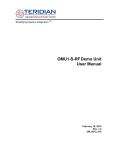
3Com V7300 Voice
Applications Suite
®
Unified Messaging Suite
Intelligent Mirroring Guide
VCX™ V7000 IP Telephony Solution
System Release 5.0
Part Number 900-0153-01 AA
Published August 2004
http://www.3com.com/
3Com Corporation
350 Campus Drive
Marlborough, MA
01752-3064
Copyright © 2004, 3Com Corporation. All rights reserved. No part of this documentation may be
reproduced in any form or by any means or used to make any derivative work (such as translation,
transformation, or adaptation) without written permission from 3Com Corporation.
3Com Corporation reserves the right to revise this documentation and to make changes in content from
time to time without obligation on the part of 3Com Corporation to provide notification of such revision
or change.
3Com Corporation provides this documentation without warranty, term, or condition of any kind, either
implied or expressed, including, but not limited to, the implied warranties, terms, or conditions of
merchantability, satisfactory quality, and fitness for a particular purpose. 3Com may make improvements
or changes in the product(s) and/or the program(s) described in this documentation at any time.
If there is any software on removable media described in this documentation, it is furnished under a
license agreement included with the product as a separate document, in the hardcopy documentation, or
on the removable media in a directory file named LICENSE.TXT or !LICENSE.TXT. If you are unable to
locate a copy, please contact 3Com and a copy will be provided to you.
UNITED STATES GOVERNMENT LEGENDS:
If you are a United States government agency, then this documentation and the software described herein
are provided to you subject to the following:
United States Government Legend: All technical data and computer software is commercial in nature
and developed solely at private expense. Software is delivered as Commercial Computer Software as
defined in DFARS 252.227-7014 (June 1995) or as a commercial item as defined in FAR 2.101(a) and as
such is provided with only such rights as are provided in 3Com’s standard commercial license for the
Software. Technical data is provided with limited rights only as provided in DFAR 252.227-7015 (Nov
1995) or FAR 52.227-14 (June 1987), whichever is applicable. You agree not to remove or deface any
portion of any legend provided on any licensed program or documentation contained in, or delivered to
you in conjunction with guide.
Unless otherwise indicated, 3Com registered trademarks are registered in the United States and may or
may not be registered in other countries.
3Com and the 3Com logo are registered trademarks of 3Com Corporation. VCX is a trademark of 3Com
Corporation.
Other brand and product names may be registered trademarks or trademarks of their respective holders.
3
CONTENTS
ABOUT THIS GUIDE
Assumptions 5
Conventions 5
Notices 5
Text 6
Related Documentation
Your Comments 7
6
INITIAL CONFIGURATION
Overview 9
Hardware Prerequisites 9
IP Configuration 10
Single Network Configuration 10
Dual Network Configuration 11
Domain Name System (DNS) Configuration 13
Sample DNS Names and Files 14
Enabling Secure Copy (SCP) and Secure Shell (SSH) Commands
Network Time Protocol (NTP) Configuration 16
Configuration 16
Verification 17
INSTALLATION
Overview 19
Primary Server Installation 19
Stopping System Software 19
Sample Installation Script (for voipbox1) 20
Secondary Server Installation 20
Sample Installation Script (for voipbox2) 20
Intelligent Mirroring Active/Standby Policy 21
Primary Intelligent Mirroring Policy 21
16
4
Balanced Intelligent Mirroring Policy 22
Switching Between Active and Standby States
OPERATION
Verifying Intelligent Mirroring Operation
Manual Switchover 26
Verifying Server Synchronization 26
Database 26
File System 27
INDEX
25
22
ABOUT THIS GUIDE
This chapter contains an overview of this guide, lists guide conventions,
related documentation, and product compatibility.
Assumptions
This guide is intended for system administrators and assumes you have
basic skills such as:
■
Basic UNIX command line usage
■
Knowledge of Solaris operating system utilities
If the information in the release notes differs from the information in this
guide, follow the instructions in the release notes.
Conventions
This section describes notice and text conventions used in this guide.
Notices
Table 1 lists notice icons used in this guide.
Table 1 Notice Icon Descriptions
Icon
Notice Type
Description
Information
note
Information that contains important features or
instructions.
Caution
Information to alert you to potential damage to a
program, system, network, or device.
Warning
Information to alert you to potential personal injury
or fatality. May also alert you to potential electrical
hazard.
6
ABOUT THIS GUIDE
Text
Table 2 lists text conventions that are used in this guide.
Table 2 Text Convention Descriptions
Convention
Description
Text represented as a screen display
This typeface represents displays that
appear on your terminal screen, for
example:
Netlogin:
Text represented as user entry.
This typeface represents information that
you must type, for example:
cd /usr/bin
Text represented as menu or sub-menu This typeface represents all menu and
names
sub-menu names within procedures, for
example:
On the File menu, click New.
Text represented by <filename>
This typeface represents a variable, for
example:
<filename>
Related
Documentation
The following lists 3Com documents that contain additional information
about the products in this release.
■
V7000 System Applications Guide
■
VCX V7210 and V7220 Installation and Initial Configuration Guide
■
VCX V7210 Administration Guide
■
VCX V7220 Administration Guide
■
VCX V7210 Configuration and Maintenance Guide
■
VCX V7220 Configuration and Maintenance Guide
■
VCX V7230 Enterprise Management Suite User Guide
■
3Com Telephone User Guide
■
3Com V7300 Voice Applications Product Overview
■
3Com V7300 Voice Applications Installation Guide
■
3Com V7300 Voice Applications Provisioning Guide
■
3Com V7300 Voice Applications User Guide
Your Comments
Your Comments
7
Your suggestions are important to us because we want to make our
documentation more useful to you.
Please send e-mail comments about this guide or any of the 3Com
Voice Products documentation and Help systems to:
[email protected]
Please include the following information with your comments:
■
Document title
■
Document part number (found on the front page)
■
Page number
■
Your name and organization (optional)
Example:
3Com® V7300 Voice Applications Suite
Messaging Applications Intelligent Mirroring Guide
Part Number 900-0153-01 Rev AA
Page 15
Please address all questions regarding the 3Com software to your
authorized 3Com representative.
8
ABOUT THIS GUIDE
1
INITIAL CONFIGURATION
This chapter provides an overview of how to configure Intelligent
Mirroring on a Primary and Secondary server for the V7300 Voice
Applications Suite.
Intelligent Mirroring is the mirroring of application data on two
independently running servers. The mirrored application data is
composed of table data and message component files.
Overview
When you configure two servers for Intelligent Mirroring:
■
One of the servers operates in the active state
■
The other operates in standby state
At any one time, either the Primary or the Secondary server can be in
the active state.
You can install the Primary and Secondary servers on the same
network or, for added reliability, you can connect each of them to an
A and a B network (see Figure 1 on page 12). Both approaches are
described in this guide.
Before you begin to install Intelligent Mirroring on the Primary and
Secondary servers, verify that you have the equipment and
information outlined in the next two sections.
Hardware
Prerequisites
The Primary and Secondary Intelligent Mirroring servers run on the same
hardware platforms that run the messaging system software.
3Com recommends that you connect each server to two different
subnetworks for added reliability. To make these connections, each
server requires two network interface cards, for a total of four cards.
10
CHAPTER 1: INITIAL CONFIGURATION
IP Configuration
3Com recommends that you define the IP configuration using the
/etc/hosts files on the two systems.
The /etc/hosts file on each server must contain identical information
about the Intelligent Mirroring configuration. Other information in the
file may vary. The examples in this document contain the information
that must be identical.
For each network to which Intelligent Mirroring is connected, you
must configure four unique IP addresses, all on the same subnetwork:
Single Network
Configuration
■
Two of these addresses are static and are assigned to the primary
network interface cards on the two systems.
■
The other two IP addresses are aliases that are dynamically assigned
based on the state (active versus standby) of the Intelligent Mirroring
servers. These addresses are not associated with any hardware.
To configure both the Primary and Secondary servers on a single network,
follow the instructions in this section. For the instructions on how to
configure the servers on two networks, see Dual Network Configuration.
3Com recommends that you configure the systems on which
Intelligent Mirroring runs so that each one is connected to two
independent networks on separate switches. This provides additional
reliability should problems develop on either network (for example, if
a switch fails). See Figure 1 on page 12.
The examples in this section are based on these assumptions:
System 1 (Primary Server)
■
System Name — voipbox1
■
IP Address (subnetwork 126) — 192.168.126.1 (associated with
the primary network interface on the Primary Server)
System 2 (Secondary Server)
■
System Name — voipbox2
■
IP Address (subnetwork 126) — 192.168.126.2 (associated with
the primary network interface on the Secondary Server)
IP Configuration
11
CAUTION: IP addresses 192.168.126.3 and 192.168.126.4 are the
dynamic alias IP addresses. Do not associate them with any network
interface.
Sample /etc/hosts File Entries for a Single Network Configuration
This section describes entries that you would add to the /etc/hosts file if
your configuration was identical to the configuration examples listed
earlier in this section.
#
# Internet host table
#
192.168.126.1 voipbox1 voipbox1a voipbox1b voipbox1c voipbox1d
192.168.126.2 voipbox2 voipbox2a voipbox2b voipbox2c voipbox2d
192.168.126.3 active activea activeb activec actived
192.168.126.4 standby standbya standbyb standbyc standbyd
CAUTION: The host names that end in a, b, c, and d are used internally
by Intelligent Mirroring or Call Builder (or both). These names must be
present in the /etc/hosts file.
Dual Network
Configuration
To configure the Primary and Secondary servers so that they are each
connected to two networks, follow the instructions in this section.
Dual network configuration is possible only if the UMS software is
running on different servers than the Call Processor software. If you are
running all VCX software on a single pair of servers, you cannot configure
UMS for dual networks.
3Com recommends that you configure the systems on which Intelligent
Mirroring runs so that each one is connected to two independent
networks on separate switches. This provides additional reliability should
problems develop on either network (for example, if a switch fails).
The examples in this section are based on the assumption that two
subnetworks (192.168.126.XXX and 192.168.127.XXX) are used. If you
choose not to use subnetworks, modify the examples accordingly.
12
CHAPTER 1: INITIAL CONFIGURATION
Figure 1 Dual Network Configuration
Primary Server
Secondary Server
Network A
Network B
System 1 (Primary Server)
■
System Name — voipbox1
■
IP Address (subnetwork 126) — 192.168.126.1 (associated with
the primary network interface on the Primary Server)
■
IP Address (subnetwork 127) — 192.168.127.1 (associated with
the secondary network interface on the Primary Server)
System 2 (Secondary Server)
■
System Name — voipbox2
■
IP Address (subnetwork 126) — 192.168.126.2 (associated with
the primary network interface on the Secondary Server)
■
IP Address (subnetwork 127) — 192.168.127.2 (associated with
the secondary network interface on the Secondary Server)
CAUTION: IP addresses 192.168.126.3, 192.168.126.4, 192.168.127.3,
and 192.168.127.4 are the dynamic alias IP addresses. Do not associate
them with any network interface.
Domain Name System (DNS) Configuration
13
Sample /etc/hosts File Entries for a Dual Network Configuration
This section describes entries that you would add to the /etc/hosts file if
your configuration was identical to the configuration examples listed
earlier in this section.
#
# Internet host table
#
192.168.126.1 voipbox1 voipbox1a voipbox1c
192.168.126.2 voipbox2 voipbox2a voipbox2c
192.168.126.3 active activea activec
192.168.126.4 standby standbya standbyc
192.168.127.1 voipbox1b voipbox1d
192.168.127.2 voipbox2b voipbox2d
192.168.127.3 activeb actived
192.168.127.4 standbyb standbyd
CAUTION: The host names that end in a, b, c, and d are used internally
by Intelligent Mirroring or Call Builder (or both). These names must be
present in the /etc/hosts file.
Domain Name
System (DNS)
Configuration
To enable proper operation of the UMS e-mail server (SMTP, POP3, and
IMAP) you must configure the DNS servers on your network.
To configure a DNS server:
1 Create a host name for the UMS e-mail server.
The domain name of the UMS e-mail server is the host name that you just
created, together with the appropriate DNS suffix.
2 Bind both the primary and secondary IP address of the e-mail server to
the host name that you just created.
If the VCX system is a single-box configuration, you need only bind the
one IP address of the system to the host name.
14
CHAPTER 1: INITIAL CONFIGURATION
3 Restart the named service on the DNS server to update the server settings
with the new configuration information.
For any PC on which you intend to run an e-mail client program,
configure the PC so that it uses, as its primary DNS server , the DNS server
that you have just configured.
Sample DNS Names
and Files
Modify these sample host and file names to conform to your network
configuration.
■
E-mail Server Host Name — umsemail
■
DNS Suffix — vcx.wan.3com.com
■
Domain Name — umsemail.vcx.wan.3com.com
Sample named.conf file on the DNS server
controls {
inet 127.0.0.1 allow { localhost; } keys { "rndc-key"; };
};
include "/etc/bind_db/rndc.key";
options {
directory "/etc/bind_db";
pid-file "/var/run/named.pid";
allow-query { any; };
forward first;
forwarders {
192.168.15.2;
192.168.15.3;
};
};
zone "." {
type hint;
file "root.hints";
};
zone "0.0.127.in-addr.arpa" {
type master;
file "master/127.0.0";
};
zone "vcx.wan.3com.com" {
type master;
file "master/vcx.wan.3com.com";
};
Domain Name System (DNS) Configuration
15
Sample file "vcx.wan.3com.com"
$TTL 86400
@
IN
SOA
vcx.wan.3com.com. root.vcx.wan.3com.com. (
200210210; serial, todays date + todays serial #
8H; refresh, seconds
2H; retry, seconds
1W; expire, seconds
1D ); minimum, seconds
NS
galaxy
High light this MX record entry
MX10 umsemail
TXT
"Voice Core eXchange, 3Com Corporation"
localhost
-A
127.0.0.1
umsemail
A
192.168.126.1
A
192.168.126.2
voipbox1
-A
192.168.126.1
voipbox2
-A
191.168.126.2
Verifying DNS Configuration
To verify that the DNS server is properly configured for UMS:
1 On a PC where you run the e-mail client, open a command window.
2 Enter this command:
nslookup umsemail
The output from the command should look something like this:
E:\UMS>nslookup umsemail
Server: galaxy.vcx.wan.3com.com
Address: 192.168.126.1
Name: umsemail.vcx.wan.3com.com
Addresses: 192.168.126.1 192.168.126.2
In this example, the domain name is resolved to two IP addresses, one for
the primary server and one for the secondary server.
3 Enter this command:
ping umsemail
Continuing with the information in this example, you would see replies
from umsemail.vcx.wan.3com.com.
16
CHAPTER 1: INITIAL CONFIGURATION
Enabling Secure
Copy (SCP) and
Secure Shell (SSH)
Commands
UMS uses shell scripts to synchronize the two servers. These scripts use
the SCP and SSH commands. For these commands to work properly in
this environment, you must configure each UMS server so that the
commands do not prompt for a password.
Perform these steps on the voipbox1 and voipbox2 servers as user app:
1 To create the private and public keys, enter this command:
ssh-keygen -t dsa
2 When you are prompted for a key location, press Enter to accept the
default.
3 When you are asked for a passphrase, press Enter to leave the
passphrase blank.
Perform these steps on the designated server only, as user app:
1 On voipbox1, copy the public key to the voipbox2 using this command:
cat ~app/.ssh/id_dsa.pub | ssh app@voipbox2 "cat - >> ~app/.ssh/authorized_keys"..
2 On voipbox2, copy the public key to the voipbox1 using this command:
cat ~app/.ssh/id_dsa.pub | ssh app@voipbox1"cat - >> ~app/.ssh/authorized_keys"..
Network Time
Protocol (NTP)
Configuration
Intelligent Mirroring requires that the clocks on the two systems be
synchronized to within 1 second.
3Com recommends that you use an external NTP server to maintain time
synchronization with Universal Time.
Configuration
To configure Network Time Protocol on the two systems:
1 On the voipbox1 system, create the /etc/ntp.conf file.
2 Edit the file and add these lines:
server 127.127.1.1
fudge 127.127.1.1 stratum 8
peer voipbox2
The IP address 127.127.1.1 designates the local oscillator (clock). This
entry is required. If no external NTP server is configured or available, the
two systems use the local oscillator. The fudge command sets the local
Network Time Protocol (NTP) Configuration
17
oscillator to stratum 8 in order to allow the two systems to use a lower
stratum server (7 or lower) if one is available. By default, the system uses
this drift file: /etc/ntp/drift.
3 On the voipbox2 system, create the /etc/ntp.conf file.
4 Edit the file and add these lines:
server 127.127.1.1
peer voipbox1
5 On the voipbox1 server, su to root and execute these commands:
/etc/init.d/ntpd stop
/etc/init.d/ntpd start
6 On the voipbox2 server, su to root and execute the same commands:
/etc/init.d/ntpd stop
/etc/init.d/ntpd start
Optionally, you can add any number of additional server entries in the
ntp.conf file.
Verification
To verify that the NTP service is properly configured, run this command:
ntpq -p
Any user can run the ntpq command.
The output from this command shows the state of all of the ntp
servers with which the local system is communicating.
18
CHAPTER 1: INITIAL CONFIGURATION
INSTALLATION
2
This chapter describes how to install Intelligent Mirroring on the Primary
Server and the Secondary Server.
Overview
Follow these instructions, in the order that they are given, when you
install and configure the servers.
1 Completely install the Primary Server before you begin to install the
Secondary Server. See the instructions in Primary Server Installation, next.
After you have installed the Primary Server, the system reboots itself.
2 Verify that the Primary Server is operational and that you can place calls.
3 Install the Secondary Server. See the instructions in Secondary Server
Installation on page 20.
Primary Server
Installation
Follow the instructions in this section to completely install, configure, and
verify the Primary Server.
The device names of the network interfaces on your systems may vary
from those used in the following examples. To obtain a list of the device
names for your network interfaces, use the ifconfig -a command.
Stopping System
Software
If any version of the Unified Messaging System software is running on
any of the machines in the configuration, you must perform these steps
on each machine:
1 Stop the application using this command:
/usr/app/gen/stopmon
2 Verify that the application is stopped using this command:
/usr/app/gen/hmm app
You should see no processes in the list.
20
CHAPTER 2: INSTALLATION
Sample Installation
Script (for voipbox1)
When you first start a VCX V7000 server, a firstboot script is run. The
script asks you questions and configures the software based on your
answers. This section shows the portion of the firstboot script that deals
with configuring Intelligent Mirroring between two VCX UMS servers.
Bold text indicates values that you must type. Press Enter after each
entry.
The example answers in this script assume that you are using voipbox1,
that voipbox1 will be the primary server, and that voipbox2 will be the
secondary server.
Intelligent Mirroring configurations
Should Intelligent Mirroring be enabled (Y/N)? [N]: Y
Name of the Remote Intelligent Mirrored System?: voipbox2
Intelligent Mirroring Alias? : active
Is this host the primary or the secondary (P/S)? : P
Enter the Device Name of the Network Card? : eth0
Enter the Device Name of the Second Network Card, enter if
only one? eth1
Enter the Standby Alias? : standby
The portion of the firstboot script that deals with UMS Intelligentigent
Mirroring has now been completed. The firstboot script continues
with other configuration questions.
Secondary Server
Installation
Sample Installation
Script (for voipbox2)
Follow the instructions in this section to completely install and configure
the Secondary Server.
When you first start a VCX V7000 server, a firstboot script is run. The
script asks you questions and configures the software based on your
answers. This section shows the portion of the firstboot script that deals
with configuring Intelligent Mirroring between two VCX UMS servers.
Bold text indicates values that you must type. Press Enter after each
entry.
Intelligent Mirroring Active/Standby Policy
21
The example answers in this script assume that you are using voipbox2,
that voipbox2 will be the secondary server, and that voipbox1 will be the
primary server.
Intelligent Mirroring configurations
Should Intelligent Mirroring be enabled (Y/N)? [N]: Y
Name of the Remote Intelligent Mirrored System? : voipbox1
Intelligent Mirroring Alias? : active
Is this host the primary or the secondary (P/S)? : S
Enter the Device Name of the Network Card? : eth0
Enter the Device Name of the Second Network Card, enter if
only one? eth1
Enter the Standby Alias? : standby
The Secondary Server now restarts itself and picks up the Line and Port
configuration from the Primary Server.
The portion of the firstboot script that deals with UMS Intelligentigent
Mirroring has now been completed. The firstboot script continues
with other configuration questions.
Intelligent
Mirroring
Active/Standby
Policy
Intelligent Mirroring uses one of two policies to determine which server
operates in the active state and which operates in the standby state. The
Primary and Balanced policies, explained next, control the two server
states.
The example answers in this script assume that you are using voipbox1,
that voipbox1 will be the primary server, and that voipbox2 will be the
secondary server.
Configuration of a mirroring policy can be done only after the firstboot
script has been completed and the VCX system has been rebooted.
Primary Intelligent
Mirroring Policy
This policy specifies that whenever the Primary Server is running, it enters
the active state. If the Secondary Server was running in the active state,
the two servers negotiate so that the Secondary Server switches to the
standby state.
22
CHAPTER 2: INSTALLATION
For new installations, the policy is set to Primary by default.
To configure the primary policy:
1 Edit this file on the Primary Server:
/usr/app/app.dir/config.app
2 Find the line that begins with:
IM_policy=
3 Modify the line, if necessary, so that it reads:
IM_policy=primary
4 Restart Call Builder on the Primary Server.
When Call Builder restarts on the Primary Server, it is in the standby state.
After 5 minutes, it switches to active state.
Balanced Intelligent
Mirroring Policy
This policy specifies that when one of the servers enters the active state, it
stays in that state until it fails or someone shuts it down.
To configure the balanced policy:
1 Edit this file on the Primary Server:
/usr/app/app.dir/config.app
2 Find the line that begins with:
IM_policy=
3 Modify the line, if necessary, so that it reads:
IM_policy=balanced
4 Restart Call Builder on the Primary Server.
Switching Between
Active and Standby
States
The Primary Server can enter the standby state in either of these two
ways:
■
When the Primary Server starts, the Secondary Server is in the active
state. Therefore, the Primary Server enters the standby state.
OR
■
Someone issues a command to force the Primary Server into the
standby state.
Intelligent Mirroring Active/Standby Policy
23
When the Primary Server is in the standby state, it periodically checks the
value of IM_policy and, depending on the value, the Primary Server may
switch from the standby state to the active state.
■
If IM_policy is set to primary, a 5-minute timer is activated. When the
timer value expires, the Primary Server switches from standby to the
active state and negotiates with the Secondary Server so that the
Secondary Server switches to the standby state.
■
If IM_policy is set to balanced, no action is taken.
24
CHAPTER 2: INSTALLATION
3
OPERATION
This chapter describes how to verify the proper operation of Intelligent
Mirroring and synchronization between the servers. It also describes how
to manually switch server states and how to resynchronize the databases
and file systems on the two servers if that becomes necessary.
Verifying Intelligent
Mirroring
Operation
To verify that Intelligent Mirroring is operating properly, perform these
steps on each server:
1 In a command window, enter this command:
xattach app
2 In the screen that appears:
a On the active server, verify that:
■
The status in the Intelligent Mirroring Status window is Active.
■
The status of each of the 4 pipes is Alive.
b On the standby server, verify that:
■
The status in the Intelligent Mirroring Status window is Standby.
■
The status of each of the 4 pipes is Alive.
■
This message is not scrolling in the Message window:
VM_INIT vm_nanch:-1
If the “VM_INIT vm_nanch: -1” message is scrolling in the Message
Window, go to the active server and type killit msg4 16 at the
command line. If this does not clear the problem, then there is a network
configuration problem.
26
CHAPTER 3: OPERATION
Manual Switchover
You can manually switch either server to the active or standby state,
provided that you have root privileges.
1 In a command window, enter this command:
xattach app
2 In the screen that appears, click one of these two items to command the
system to switch state:
■
Scripts/Spawn vssu_active
■
Scripts/Spawn vssu_stanby
3 In the Intelligent Mirroring Status window, verify that the state changes
appear immediately.
4 In the Message window, verify that the messages indicate the progress of
the switchover.
Example:
The following message window sequence is typical when you command
the active server to go to standby mode:
../app_ss.c:137 Request to become standby
../app_ss.c:193 Remote end has requested to become active
Shutdown from msg4
This side is standby
VSSI_STNDBY vm_nanch=29028
Verifying Server
Synchronization
Database
You can verify that the databases and the file systems on the Primary and
Secondary Servers are synchronized.
To verify database synchronization, at the command line, enter this
command:
tblcmp
If the databases are synchronized, you see this message:
Tables are identical
Verifying Server Synchronization
27
If the databases are not synchronized, you see a list of the records that
are different.
The synchronization of the Primary and Secondary servers is a real-time
activity. The tblcmp utility gives accurate results only on an idle system
(one that is not processing telephone calls).
To re-synchronize the databases:
1 On the active server, at the command line enter this command:
xattach app
2 In the screen that appears, click Scripts/Spawn vssu_sync.
3 In the blue Tables window that appears, click the SS button to select all
the tables that are synchronized with Intelligent Mirroring.
4 Page down until you see checked boxes that indicate that the associated
tables are selected for synchronization.
5 Click the UD button to synchronize the selected tables.
The standby server is updated and restarted.
File System
To verify that the file systems are synchronized, follow the procedures in
this section.
At the command line on both the Primary and Secondary Servers:
1 Enter this command:
diffmsg
If there are many files on the system, the diffmsg utility may take some
time to complete operation.
When the diffmsg utility stops, the system displays these two file counts:
■
Files to copy: — The number of files that exist on the other server
but do not exist on the local server.
■
Files to remove: — The number of files that exist on the local server
but do not exist on the other server.
If the value of files to copy is 0 (zero), then the file system is synchronized
from the perspective of the local server.
2 If the value of files to copy is not 0 (zero), then enter the command:
diff2rcp
28
CHAPTER 3: OPERATION
This command creates a shell script (/usr/app/app.dir/diffmsg.rcp) that
you can run from the command line to copy the missing files from the
other server.
3 If the value of files to remove is not 0 (zero), then run this command on
the local server:
diffmsg
and run this command on the other server:
diff2rcp
To run the synchronization command line utilities, both servers must have
secure shell information configured (see “Enabling Secure Copy (SCP)
and Secure Shell (SSH) Commands” on page 16).
INDEX
B
balanced mirroring, policy
22
C
comments on documentation
configuration
dual network 11
hardware 9
IP addresses 10
overview 9
single network 10
conventions
text 5
7
installation preparation
hardware 9
IP addresses 10
overview 9
installation script
sample for primary server 20
sample for secondary server 20
M
mirroring operation, verifying 25
mirroring policies 21
balanced 22
primary 21
switching between balanced and primary
D
N
database synchronization 27
documentation
related 6
documentation comments 7
network configuration
dual network 11
single network 10
Network Time Protocol 16
E
P
enabling
scp command
ssh command
policies for mirroring 21
primary mirroring, policy 21
primary server, installation 19
16
16
F
R
file system, synchronization
H
hardware 9
hosts file (sample)
11, 13
I
installation
overview 19
primary server 19
secondary server 20
27
resynchronizing
databases 27
file system 27
S
sample hosts file 11, 13
scp command 16
secondary server, installation 20
server operation, verifying 25
server synchronization, verifying 26
ssh command 16
22
30
INDEX
synchronizing
databases 27
file systems 27
servers 26
time 16
with scp and ssh commands
16
T
time synchronization
16
U
users, intended
5
V
verifying
database synchronization 27
file system synchronization 27
proper mirroring operation 25
server synchronization 26