1
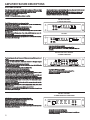
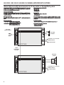
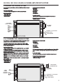
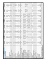
R
EVOLUTION OF POWER
AXL
AMPLIFIERS
AXL1050.2 / AXL1650.2 / AXL3050.2
AXL1050.4 / AXL1450.4 / AXL4050.4
AXL1550.1 / AXL2550.1
AXL SERIES AMPLIFIERS
Congratulations on your purchase and thank you for supporting AUTOTEK! The AXL Series products have been
designed to a very high level of performance, with features unavailable in similarly priced amplifiers. These
amplifiers have variable crossovers built in, with added touches such as subsonic filter, bass equalization and a
remote Level control module (some models) that allows subwoofer Level control from the drivers seat. The multi
channel models have kept your factory headunit and existing controls in mind by offering high level inputs which
allow for your OEM radio to remain in place. Please read through this manual completely as we have compiled a
guide that will keep you on the road and enjoying your music for years to come.
The car audio professionals at Maxxsonics recommend that you only use one of the MAXXLINK amplifier
installation kits to install this amplifier. The MAXXLINK amplifier installation kits are designed to deliver proper
power and fusing to the amplifier from the vehicles electrical system. Additionally, the kit includes signal cables
(RCA's) that are designed to reject noise and improve signal quality from the source unit to the pre-amplifier
section. This amp is going to sound unbelievable.
Use of MAXXLINK products ensures that your amplifier will deliver maximum performance for years to come.
Maxxsonics is so confident in this amplifier, installed properly with a qualifying MAXXLINK amp kit, you can add up
to 12 months of additional warranty coverage to this amplifier! For more information, please check out
MAXXLINKAudio.com/Warranty. Check out all MAXXLINK products for your installation at MAXXLINKAudio.com
TREAD LOUDLY!
INDEX
PAGE
General Installation Procedure.........................................................................................................................................................1
Amplifier Feature Descriptions..........................................................................................................................................................2
AXL1050.2 / AXL1650.2 / AXL3050.2 2-CHANNEL AMPLIFIER APPLICATIONS........................................................................3-4
Full range stereo / Full range mono
AXL1050.4 / AXL1450.4 / AXL4050.4 4 CHANNEL AMPLIFIER APPLICATIONS............................................................................5
4, 3 and 2 channel full range / 2 way active, with mono bass /
front/rear high pass using a 2 channel model for mono sub bass
AXL1550.1 / AXL2550.1 A/B-CLASS 1 CHANNEL AMPLIFIER APPLICATIONS............................................................................6
Basic mono amplifier application
Features and Specifications..............................................................................................................................................................7
Setting Up Systems After Installation For Best Performance..............................................................................................................8
Troubleshooting and Diagnostics......................................................................................................................................................9
Product Warranty............................................................................................................................................................................10
Be sure to check out the Maxxsonics Extended Limited Warranty
Program on the bottom of the page
MAXXLINK Accessories............................................................................................................................................................11-12
Be sure to check us out at
www.youtube.com/maxxsonicsusainc
for product reviews and tutorials for
getting the most out of your audio system.
© 2012 Maxxsonics USA, Inc. All rights reserved. All Maxxsonics USA, Inc.
trademarks, including, Maxxsonics, the M Logo, the Maxxsonics logo and
MAXXLINK are owned by Maxxsonics USA, Inc. Use of the ® in connection with a
mark of Maxxsonics USA, Inc. indicates that the mark is registered in at least the
United States.
GENERAL INSTALLATION PROCEDURE
System Design
The success of any car stereo system relies on several factors, such as the system design, execution of the installation, and system setup. Please
remember that any system is only as good as its weakest link.
Please remember that higher power systems are not necessarily useful purely for high sound pressure levels, but also to establish a headroom capability, to
reproduce musical peaks cleanly without distortion. Lower power amplifiers will clip earlier than their more powerful cousins, and cause loudspeaker failure when
overdriven, due to the harmonics generated by a clipped signal, thus overheating voice coils.
Amplifiers should be mounted with the fins running horizontally for best convection cooling, to minimize overheating. Purchase the best quality RCA cables you can
afford, for reliability and less engine noise interference in the audio system.
Installation
WOOD
It is highly recommended that the amplifier be mounted to a board of MDF or other solid
structure using the 4 mounting screws provided. Avoid mounting the
amplifier to metal as this can introduce noise and other unwanted issues. When mounting
the amplifier, ensure that it is mounted HORIZONTALLY, as shown in the diagram above, for
optimal heat dissipation. Mounting amplifiers to speaker enclosures is not recommended as
this can cause damage to the amplifier components. When choosing a location for
mounting the amplifier, ensure that you check for clearance from wires, gas tank, electrical
devices and brake lines etc.
General:
Run the wiring so that RCA cables are at least 18“ away from power and speaker cables. Keep RCA cables away from electrical devices in the vehicle that can cause
electrical noise, such as electric fuel pumps, emission control modules and other on-board electronic modules.
Power and ground connections(see the features matrix on page 7 for proper gauge cables per amplifier):
Use a sufficient gauge power cable and ground cable using the chart below as reference to what size wire you require. In a multi amplifier system, add the total value
of the manufacture recommended fusing to get your total system amperage. Some applications may require multiple runs of power wire to meet the system
requirements. In multi amplifier systems it is advisable to mount a large enough fuse right at the battery, and run one or multiple +12 volt power cables to a fused
distribution block near the amplifiers. It is then a simple matter to connect the +12 volt terminal of each amplifier to the distribution block. During this process, please
ensure that the main power fuse is removed to avoid shorting the electrical system. The main fuse must be within 12” of the vehicles battery.
Ground each amplifier with as short a ground lead as possible directly to the vehicle chassis using 4 gauge wire or equivalent to the size of the amplifiers’ power wire.
Use a ground distribution block, if you wish, but it is extremely important to keep the main ground lead from this distribution block to the chassis as short as possible ,
not more than 12“. The ground connection integrity to the chassis is very important, and the best way to achieve a good, solid electrical and mechanical contact is to
use a large round crimp lug, crimped and soldered to the ground cable. The next step is to scrape the paint off the vehicle chassis , slightly larger than the ground
lug, at the connection point. Drill a clearance hole in the chassis, the same size as the lug hole, and use a bolt, spring washer and nut to securely fasten the ground
lug. Use petroleum jelly to coat the bolt/lug connection, to prevent oxidization with time.
TIP: Use the same approach when installing head units, equalizers or any audio equipment for that matter - run short individual grounds from each piece directly to
the vehicle chassis, to minimize ground loops and system noise. All power, ground and speaker connections should be crimped and soldered for reliability. Make sure
that none of the cable insulation can chafe against exposed metal in the vehicle, causing short circuits to the chassis.
WIRE LENGTH
SYSTEM
AMPERAGE
10-13 ft.
13-16 ft.
16-19 ft.
19-22 ft.
22-28 ft.
8
6
4
4
4
4
50-65
6
4
4
4
4
2
68-85
4
4
2
2
2
0
85-105
4
2
2
2
2
0
105-125
4
2
0
0
0
0
125-150
2
0
0
0
0
0
35-50
WIRE GAUGE
7-10 ft.
NOTE: This Matrix is a general rule
of thumb. Please refer to the
manufacturers specific
requirements. AXL specifications
can be found on page 7.
Safe connection sequence:
After all cables are run, connect speaker wires to the speakers and amplifiers, then run and plug in RCA cables. Next, connect all power, ground, and remote turn on
leads. Now connect all +12 volt cables to the amplifier/s and distribution blocks and fuse holders. Finally, connect the main +12 volt cable to the battery, with the main
fuse removed, and we are almost ready to power up the system.
Power up the system:
The following procedure may seem like overkill, but there is nothing more frustrating when turning on a system for the first time, and it does not work properly
immediately.
First, make sure the head unit is off, and turn all level controls to minimum (counterclockwise), including the head unit volume control. Set all equalizers to 0 dB (no
boost), and all crossover frequency controls at approximate frequencies, as recommended by the loudspeaker manufacturer. Set all input selector and crossover
switches as required for the application. Remove all amplifier fuses, and insert the main fuse at the battery. If the fuse does not blow, you can insert the fuse in one of
the amplifiers, and we are ready to turn on the system. Turn the head unit on, insert a CD, or select a radio station, and increase the head unit volume control. If the
system sounds fine, turn off the head unit, and install fuses in the remaining amplifiers, one by one, till the complete system is powered up and functioning properly.
1
AMPLIFIER FEATURE DESCRIPTIONS
AXL AMPLIFIERS:
Each multi channel model is capable of 4 & 2-Ohms stereo per channel, or 4-Ohms mono bridged
operation. The AXL1550.1 is stable at 4 & 2-Ohms while the AXL2550.1 is stable at 4, 2 & 1-Ohm.
The input sensitivities for rated output powers are variable from 0.2 volts to 6 volts.
All crossovers are fully variable in their respective ranges.
Crossover filters are 12dB/Octave.
A POWER LED indicates the powered up and turned on condition
All Autotek amplifiers feature a comprehensive diagnostic system, with speaker lead short circuit, and
amplifier DC faults indicated by the red “PROTECT” LED.
CAUTION: DO NOT OPERATE ANY AMPLIFIER BELOW THE INTENDED IMPEDANCE. YOU
WILL CAUSE DAMAGE TO THE AMPLIFIER THAT WILL NOT BE COVERED UNDER THE
WARRANTY PRINTED IN THE BACK OF THE MANUAL.
AXL1050.2 / AXL1650.2
2-CHANNEL AMPLIFIERS
The X-OVER slide switch selects the internal crossover functions:
-The input signal is routed directly to the LINE OUT RCA jacks, regardless of the X-OVER setting
simplifying daisy chaining of amplifiers.
-HPF: Selects the built in HIGH PASS filter, variable from 60 Hz to 1.2kHz.
-FULL: Bypasses all crossovers for full frequency range operation.
-LPF: Selects the built in LOW PASS , variable from 30 Hz to 250Hz.
MODE: The mode switch allows you to choose Stereo for full range 2 channel operation or MONO
for bridging operation
HIGH INPUT: If your radio/CD player does not have unbalanced (RCA) outputs, you can use the
HIGH level (wire) inputs.
LINE INPUT: The line input accepts unbalanced (RCA) inputs from 0.2V to 6V.
LINE OUTPUT: The line output passes through signal from the line inputs which allows you to daisy
chain multiple amplifiers from one signal.
LINE OUT
LINE INPUT
L
LEVEL
BASS EQ
HPF
X-OVER
LPF
MODE
L
GND
HI INPUT
R
0.2V 0dB 12dB 60Hz 1.2kHz30Hz 250Hz FULL LPF HPF
6V
MONO
STEREO
R
AXL3050.2
LINE INPUT
LINE OUT
L
BASS EQ
LEVEL
HPF
X-OVER
LPF
MODE
L
GND
HI INPUT
6V
FULL LPF HPF
0.2V 0dB 12dB 60Hz 1.2kHz30Hz 250Hz
MONO
STEREO
REMOTE
CONTROL
R
R
Note that the LOW PASS signal is MONO.
-In the LPF position, the HIGH PASS filter acts as a subsonic filter.
-When the LPF mode is selected, a 0 to +12dB, at 45Hz, BASS -EQ is also
switched in.
AXL1050.4 / AXL1450.4 / AXL4050.4
4-CHANNEL AMPLIFIERS
The 4 channel amps have the same features as the 2 channel models except that there are 2 sets of
controls.
1 set for channels 1 & 2 and 1 set for channels 3 & 4.
In addition, the 4 channel models have a MODE switch which allows for RCA signal routing and
selection.
The X-OVER slide switch selects the internal crossover functions:
-The input signal is routed directly to the LINE OUT RCA jacks, regardless of the X-OVER setting
simplifying daisy chaining of amplifiers.
-HPF: Selects the built in HIGH PASS filter, variable from 60 Hz to 1.2kHz.
-FULL: Bypasses all crossovers for full frequency range operation.
-LPF: Selects the built in LOW PASS , variable from 30 Hz to 250Hz.
MODE: The mode switch allows you to choose routing of signal within the amp.
-2CH Mode: In this mode, only inputs 1&2 are used. Input 1 (left)is internally routed to speaker
terminals 1&3, while input 2 (right)is internally routed to speaker terminals 2&4.
This is useful when only a stereo source is available. CH1&2 can be set to high pass for highs, and
CH3&4 to low pass for lows, for instance, or set to full range, depending on the application.
-3CH mode: In this mode, input 1&2 signals are internally mono mixed, and routed as a mono signal
to 1&2 speaker terminals. These outputs can be mono bridged into one speaker. Set CH1&2 to low
pass. Input 3 is internally routed to speaker terminal 3, and input 4 is internally routed to speaker
terminal 4. Set CH3&4 to high pass.
-4CH Mode: In this mode, each input is internally routed to the corresponding speaker terminals,
with input 1 to speaker terminal 1 etc.
HIGH INPUT: If your radio/CD player does not have unbalanced (RCA) outputs, you can use the
HIGH level (wire) inputs.
LINE INPUT: The line input accepts unbalanced (RCA) inputs from 0.2V to 6V.
LINE OUTPUT: The line output passes through signal from the line inputs which allows you to daisy
chain multiple amplifiers from one signal.
X-OVER
MODE
X-OVER
INPUT
LPF HPF FULL
OUTPUT
INPUT
CH1
LPF
30Hz
250Hz
HPF
BASS EQ
60Hz 1.2kHz
0dB 12dB
CH2
CH3
CH4
FULL HPF LPF
GND
2CH 3CH 4CH
GND
HIGH INPUT
LEVEL
6V
CHANNEL 1/2
CH1
CH3
CH2
CH4
0.2V
LEVEL
BASS EQ
6V
0dB
0.2V
12dB
HPF
60Hz 1.2kHz
LPF
30Hz
250Hz
CHANNEL 3/4
Note that the LOW PASS signal is MONO.
-In the LPF position, the HIGH PASS filter acts as a subsonic filter.
-When the LPF mode is selected a 0 to +12dB, at 45Hz,
BASS EQ is also switched in.
AXL1550.1 / AXL2550.1
1-CHANNEL MONO BLOCK AMPLIFIERS
-SUBSONIC: Allows you to adjust the crossover filter from 15Hz to 55Hz.
-LPF: Allows yo to adjust the LOW PASS crossover filter from 40Hz to 150Hz.
LEVEL: Adjusts the input sensitivity from 0.2 volts to 6 volts.
BASS EQ: The Bass EQ is adjustable from 0db to 12dB.
REMOTE: This is the input jack for the remote Level control.
LINE INPUT: The line input accepts unbalanced (RCA) inputs from 0.2V to 6V.
LINE OUTPUT: The line output passes through signal from the line inputs which allows you to daisy
chain multiple amplifiers from one signal.
BASS EQ
POWER
SUB SONIC
LOW PASS
0dB
REMOTE
CONTROL
12dB
15Hz
55Hz
40Hz
150Hz
OUTPUT
LEVEL
PROTECT
6V
INPUT
L
L
R
R
0.2V
The AXL1550.1 is capable of 4 & 2-Ohm loads.
The AXL2550.1 is capable of 4, 2 & 1-Ohm loads.
Operating the amp below the Ohm listed above can cause damage to the amp
not covered in the warranty.
2
AXL1050.2 / AXL1650.2 / AXL3050.2 2 CHANNEL AMPLIFIER APPLICATIONS
FULL RANGE STEREO
This is the most basic application for the AXL Series 2 channel amplifiers.
1. Interconnect cable checklist:
Connect the LINE INPUTS to the Radio/CD with good quality RCA cables.
2. Crossover Switch:
The X-OVER switch must be in the FULL position.
The MODE switch must be in the STEREO position.
3. Crossover frequency control checklist:
N/A for full range operation.
4. Line Level:
Refer to the section “Setting up systems after installation for best performance”.
NOTE: Minimum final loudspeaker impedances:
4 &-2-Ohms stereo mode or 4-Ohms mono mode
This amplifier will not do 1-Ohm stereo or 2/1-Ohm mono operation.
FULL RANGE
STEREO LINE INPUT
GND
BASS EQ
0.2V 0dB 12dB 60Hz 1.2kHz30Hz 250Hz FULL LPF HPF
LEVEL
6V
HPF
LPF
TO BATTERY + 12 volts VIA FUSE
X-OVER
GND REM +12V
HI INPUT
+ LEFT -
L
R
BRIDGED
LINE INPUT
+ RIGHT -
LINE OUT
L
R
FULL RANGE
SPEAKERS
STEREO
MODE
MONO
REMOTE TURN-ON
CHASSIS GROUND
MONO
LINE OUT
Minimum final loudspeaker impedance:
- 4-Ohms mono.
LINE INPUT
SUBWOOFER
L
GND
HI INPUT
BASS EQ
HPF
LPF
X-OVER
0.2V 0dB 12dB 60Hz 1.2kHz30Hz 250Hz FULL LPF HPF
LEVEL
6V
FUSE
R
TO BATTERY + 12 volts VIA FUSE
STEREO
MODE
MONO
POWER INPUT
GND REM +12V
L
R
MONO LINE INPUT
VIA Y-ADAPTER
FROM MONO SOURCE
Suggested Crossover frequency control settings:
-LPF: 11 o’clock
-BASS EQ: 3 o’clock
BRIDGED
Interconnect cable checklist:
A MONO signal source is required, such as would be available from the mono sub bass
output of an active crossover, whether stand alone, or built into a head unit or equalizer.
Important: Do not be tempted to connect the hot, or positive outputs, from any source
together to obtain a mono signal, as this could very well damage the output stage of that
source.
It is necessary to feed the SAME signal to both left and right inputs via a Y-adapter RCA
cable. Connect the mono speaker positive terminal to the LEFT +, and its negative
terminal to RIGHT -.
Switch setting checklist:
- The X-OVER switch must be in the LPF position.
- The MODE switch must be in the MONO position.
SPEAKER OUTPUT
+ LEFT + RIGHT -
This application illustrates the basic mono bridging method for all Autotek 2 channel
amplifiers.
REMOTE TURN-ON
CHASSIS GROUND
The HIGH LEVEL inputs are used when the radio/CD player does not have RCA cable outputs. You can connect the radio/CD player speaker wires directly
to the amplifier via the high Level Inputs.
Use both connectors for 4 CH amplifiers
Use this connector for 2 CH amplifiers
GRAY: CH 1 Speaker Input +
ORANGE: CH 3 Speaker Input +
BROWN: CH 1 Speaker input PINK: CH 3 Speaker input Black: Chassis Ground
Black: Chassis Ground
GREEN: CH 2 Speaker Input BLUE: CH 4 Speaker Input White: CH 2 Speaker Input +
YELLOW: CH 4 Speaker Input +
3
AXL1050.2 / AXL1650.2 / AXL3050.2 2-CHANNEL AMPLIFIER APPLICATIONS
Stereo high pass with mono low-pass in a 2 way active, or bi-amplified system
In this application we will use a 2 channel amplifier for the high frequencies, and a second
one for the low frequencies, or mono sub bass. Please consult the speaker specifications
to determine maximum amplifier power requirements.
Crossover frequency control checklist:
Highs amplifier:
- HI PASS: 100 Hz
- LOW PASS: N/A
Interconnect cable checklist:
Connect the inputs of the HIGHS amplifier to a Radio/CD with good quality RCA cables.
Connect the LINE OUT of the HIGHS amplifier to the inputs of the BASS amplifier with a
stereo RCA to RCA cable.
Lows amplifier:
- HI PASS (Subsonic filter): 10 Hz to 40 Hz
- LOW PASS: 80 Hz
Mono bass woofer wiring:
Connect the mono speaker positive terminal to the LEFT +, and its negative terminal to
RIGHT -.
Please note that these frequency points are suggestions only. Refer to the loudspeaker
manufacturer specifications and the section “Setting up systems after installation for best
performance”
Switch setting checklist:
- Highs amplifier: X-OVER switch in the HPF position.
MODE switch in the STEREO position.
- Lows amplifier: X-OVER switch in the LPF position.
MODE switch in the MONO position.
Level control checklist:
- Refer to the section “Setting up systems after installation for best performance”
Minimum final loudspeaker impedances:
- 2-Ohms per channel stereo.
- 4-Ohms mono bridged.
BRIDGED
LINE INPUT
L
R
FULL RANGE
SPEAKERS
GND
BASS EQ
0.2V 0dB 12dB 60Hz 1.2kHz30Hz 250Hz FULL LPF HPF
LEVEL
6V
HPF
LPF
TO BATTERY + 12 volts VIA FUSE
X-OVER
GND REM +12V
HI INPUT
+ LEFT -
LINE OUT
L
R
+ RIGHT -
FULL RANGE
STEREO LINE INPUT
REMOTE TURN-ON
STEREO
MODE
MONO
CHASSIS GROUND
STEREO
INTERCONNECT
RCA CABLE
BRIDGED
LINE INPUT
L
R
GND
BASS EQ
HPF
LPF
X-OVER
0.2V 0dB 12dB 60Hz 1.2kHz30Hz 250Hz FULL LPF HPF
LEVEL
6V
TO BATTERY + 12 volts VIA FUSE
GND REM +12V
HI INPUT
+ LEFT -
LINE OUT
L
R
STEREO
MODE
MONO
4
+ RIGHT -
MONO BASS
SPEAKER
REMOTE TURN-ON
CHASSIS GROUND
AXL1050.4 / AXL1450.4 / AXL4050.4 4 CHANNEL AMPLIFIER APPLICATIONS
4 CHANNEL FULL RANGE SYSTEM
Here we show how to use the 4 channel amplifiers as straight forward discrete 4 channel
full range units.
Interconnect cable checklist:
- Connect the four inputs of the amplifier to a Radio/CD with quality RCA cables.
Switch setting checklist:
- 1/2CH X-OVER: FULL
- 3/4CH X-OVER: FULL
- MODE: 4 CHANNEL
Crossover frequency control checklist:
Channels 1/2:
- HI PASS: N/A
- LOW PASS: N/A
Channels 3/4:
- HI PASS: N/A
- LOW PASS: N/A
Level control checklist:
- Refer to the section “Setting up systems after installation for best performance”
Minimum final loudspeaker impedances:
- 2-Ohms per channel.
- CH3 +
- CH4 +
BRIDGED
FULL RANGE
SPEAKERS
X-OVER
LEVEL
LPF HPF FULL
6V
MODE
BASS EQ
0.2V
0dB 12dB
2CH 3CH 4CH
HPF
CHANNEL 1/2
60Hz 1.2kHz
BRIDGED
- CH1 +
- CH2 +
250Hz
LPF
30Hz
FULL RANGE
STEREO LINE INPUTS
CH4
CH3
OUTPUT
CH1
INPUT
CH2
INPUT
X-OVER
FULL HPF LPF
CH1
CH2
GND
CH3
HPF
60Hz 1.2kHz
HIGH INPUT
GND
12dB
CHANNEL 3/4
BASS EQ
0dB
GND REM +12V
0.2V
LEVEL
6V
TO BATTERY + 12 volts VIA FUSE
REMOTE TURN-ON
CH4
250Hz
LPF
30Hz
CHASSIS GROUND
2 or 3 CHANNEL FULL RANGE SYSTEM
Here we show how to use the 4 channel amplifiers as full range 2 or 3 channel units by
taking advantage of the mono bridging capability of all Autotek amplifiers.
The following example shows how to create a 3 channel system by mono bridging
channel pair 1 / 2. In order to create a 2 channel system, simply follow the example to
also mono bridge channel pair 3 / 4.
Interconnect cable checklist:
- Connect the inputs of channel pair 3 / 4 to a suitable stereo source, e.g. a head unit
with good quality RCA cables.
- A MONO signal source is required to bridge channel pair 1 / 2, such as would be
available from the mono sub bass output of an active crossover, whether standalone,
or built into a head unit or equalizer.
Important: Do not be tempted to connect the hot, or positive outputs, from any source
together to obtain a mono signal, as this could very well damage the output stage of
that source.
- It is necessary to feed the SAME signal to both left and right inputs via a Y-adapter
RCA cable.
- Connect the mono speaker positive terminal to the CH1 +, and its negative terminal
to CH2 - as shown.
Switch setting checklist:
- 1/2CH X-OVER: FULL
- 3/4CH X-OVER: FULL
- MODE: 3 CHANNEL
Channels 3/4:
- HI PASS: N/A
- LOW PASS: N/A
TIP: If you are using the mono sub bass output of an active crossover, there is nothing
wrong with switching in the low pass filter in these amplifiers for a steeper low pass
rolloff.
Level control checklist:
- Refer to the section “Setting up systems after installation for best performance”
Minimum final loudspeaker impedances:
- 2-Ohms per channel in stereo mode.
- 4-Ohms mono bridged.
MONO SPEAKER
OR SUBWOOFER CH1/2
- CH3 +
- CH4 +
BRIDGED
X-OVER
LEVEL
LPF HPF FULL
6V
MODE
BASS EQ
0.2V
0dB 12dB
2CH 3CH 4CH
HPF
CHANNEL 1/2
60Hz 1.2kHz
BRIDGED
- CH1 +
- CH2 +
250Hz
LPF
30Hz
FULL RANGE
SPEAKERS CH3/4
CH4
CH3
OUTPUT
CH1
INPUT
CH2
INPUT
X-OVER
CH1
CH2
GND
CH3
HPF
60Hz 1.2kHz
HIGH INPUT
GND
12dB
CHANNEL 3/4
BASS EQ
0dB
TO BATTERY + 12 volts VIA FUSE
CH4
250Hz
LPF
30Hz
GND REM +12V
FULL HPF LPF
0.2V
LEVEL
6V
1 MONO
1 STEREO
FULL RANGE
LINE INPUTS
Crossover frequency control checklist:
Channels 1/2:
- HI PASS: N/A
- LOW PASS: N/A
REMOTE TURN-ON
CHASSIS GROUND
5
AXL1550.1 / AXL2550.1 1 CHANNEL AMPLIFIER APPLICATION
Basic application
These sub bass amplifiers can be used in any of the bi-amplification systems described in
this manual, replacing the 2 channel amplifiers as per the illustrations.
Interconnect cable checklist:
Connect the inputs to a suitable source, e.g. a head unit with good quality RCA cables.
Connect the LINE OUT to the inputs of the system highs amplifier.
Use at least #12 gauge speaker wiring. The amps have dual speaker terminals,
simplifying the hookup of multiple speakers. These are 1 channel amplifiers.
Crossover frequency control checklist:
LOW PASS: 80Hz (approximately 11 o’clock)
SUBSONIC:35Hz (approximately 1 o’clock)
BASS EQ: 12 o’clock max
Level control checklist:
Refer to the section “Setting up systems after installation for best performance”
Minimum final loudspeaker impedance:
AXL1550.1: 2-Ohms
AXL2550.1: 1-Ohm
-
POWER
PROTECT
+
+
12dB
BASS EQ
0dB
SPEAKER
-
REMOTE
CONTROL
MONO
SUBWOOFER
55Hz
SUB SONIC
15Hz
150Hz
FUSE
LOW PASS
40Hz
L
R
+12V
0.2V
LEVEL
6V
L
GND
INPUT
POWER
REM
OUTPUT
R
TO BATTERY + 12 Volts VIA FUSE
REMOTE TURN-ON
CHASSIS GROUND
MONO LINE INPUT
VIA Y-ADAPTER
FROM MONO SOURCE
FULL RANGE
STEREO LINE INPUT
Y-ADAPTOR
GND
POWER
REM
+12V
FUSE
+
+
SPEAKER
-
-
PARALLEL MONO
SUBWOOFERS
2-OHMS EACH MINIMUM
6
NOT USED
Note: You can use the Radio/CD designated mono line output or a full range stereo line output.
For full range stereo line output, you will need an optional “Y-Adaptor” as shown.
7
Yes
PART: A1112