1
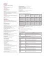
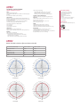
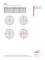
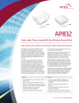
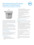
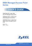
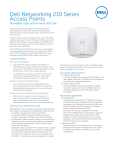
AP832e
AP832i
AP832
Dual-radio, Three-stream 802.11ac Wireless Access Point
High-performance wireless connectivity for high-density environments
The AP832 is the industry’s first 802.11ac access
point capable of supporting two concurrent
5 GHz 3x3:3ss radios, designed for high-density
deployments in large offices, schools, universities,
hospitals, hotels, and large retail stores. The AP832
supports an aggregate 2.6 Gbps data rate for the
most demanding business applications like video
and voice.
to a second layer, and patient applications can be
placed on a third channel layer.
The AP832 access point allows administrators
to prioritize applications to improve the user
experience with Meru’s unique Context Aware
Layers technology. For schools, this means
Learning Management System applications can
be assigned to one dedicated channel layer, while
online classroom video feeds can be dedicated
to another channel layer. For healthcare, lifecritical applications such as patient monitoring
can be dynamically assigned to one channel layer,
doctor and nursing applications can be assigned
Additionally, Meru’s single-channel technology
allows the AP832 to leverage the 802.11ac design
for pervasive deployment of 80 MHz channels in
real-world deployments, which effectively doubles
the available data rate and dramatically increases
throughput availability for Meru customers.
Features
• Supports IEEE 802.11ac-Draft with dual radios and
three spatial streams
The AP832 also provides unique roaming support
because Meru enables the network (not the
client) to control roams via our Air Traffic Control®
technology, resulting in the industry’s lowest
roaming latency figures–a true zero-handoff.
Like other Meru access points, the AP832 integrates
seamlessly with our E(z)RF® network management
system, Identity Manager, and other application
solutions to bring intelligent management and
resilient wireless services to your network.
Benefits
• Supports multiple wireless deployment options
• Provides an optimized 802.11ac experience in
the industry with Very High Throughput (VHT)
capabilities
• Support for multiple operating modes: centralized,
distributed, mesh, bridged, and VPN tunnel modes
• No channel planning, and delivers seamless
mobility
• Integration with Meru controllers and
management software applications
• Offers flexible deployment options for diverse
customer requirements
• Supports either internal or external antennas
• Offers full management and security assurances
• Provides a choice of two models to suit your needs
For more information, visit www.merunetworks.com
AP832
TECHNICAL SPECIFICATIONS
QoS
WMM support
Dynamic WMM rate adaptation
Configurable QoS rules per user and application
OPERATING MODES
Centralized deployment mode
Distributed deployment mode
Remote VPN tunnel mode
SECURITY
WEP, WPA-PSK, WPA-TKIP, WPA2-AES, 802.11i, 802.1X (EAP-TLS, EAPTTLS, PEAP, LEAP, EAP-FAST, EAP-SIM, EAP-AKA, and EAP-MD5)
802.1X and captive portal authentication against local database on the
controller, RADIUS, and Active Directory
RADIUS-assisted per-user and per-ESSID access control via MAC filtering
MANAGEMENT
Centrally managed by any Meru controller running System Director
Automatically discovers controllers and downloads configuration settings
for plug-and-play deployment
Upgrades and management using System Director/E(z)RF® Network
Manager
Support for SNMP
WIRELESS SPECIFICATIONS
Model Introduction
AP832i dual-radio, dual-band IEEE Std 802.11a/b/g/n/ac-Draft access
point with six internal omnidirectional antennas
AP832e dual-radio, dual-band IEEE Std 802.11a/b/g/n/ac-Draft access
point with six RP-SMA connectors and six external omnidirectional
antennas
Supported radio technologies
Dual-band, dual-radio access point
3x3:3SS (three spatial streams)
Indoor application
Supported 2.4 GHz (TurboQAM Mode) and 5.x GHz for dual-band, dualradio operation, data rate up to 1.9 Gbps
Supported dual 5.x GHz IEEE Std 802.11ac operation with RF collocation
(FCC Permit by Ask provision), data rate up to 2.6 Gbps
Supported transmit beam-forming (TxBF)
IEEE Std 802.11ac Draft standard
IEEE Std 802.11n/ac with Draft Orthogonal Frequency Division
Multiplexing (OFDM)
IEEE Std 802.11b with Direct Sequence Spread Spectrum (DSSS)
IEEE Std 802.11ac Draft with 20/40/80 MHz (VHT20/40/80) channel width
IEEE Std 802.11n with 40 MHz (HT40) channel width
IEEE Std 802.11a/g with 20 MHz channel
IEEE Std 802.11b with 5 MHz channel
Supported Modulation
IEEE Std 802.11ac Draft: BPSK, QPSK, 16-QAM, 64-QAM, 256-QAM
IEEE Std 802.11a/g/n: BPSK, QPSK, 16-QAM, 64-QAM
IEEE Std 802.11b: BPSK, QPSK, CCK
Featured 256-TurboQAM modulation for 2.4 GHz and 5 GHz operations
Supported MCS Index
Supported MCS0~MCS9 for IEEE Std 802.11ac Draft
Supported MCS0~MCS15 for IEEE Std 802.11n
Supported Frequency Bands
2.400 ~ 2.4835 GHz (ISM)
5.150 ~ 5.250 GHz (UNII-1)
5.250 ~ 5.350 GHz (UNII-2, upon DFS approval)
5.470 ~ 5.725 GHz (UNII-2 Extended, upon DFS approval)
5.725 ~ 5.825 GHz (UNII-3)
Country-specific restrictions apply; adjusted by controller upon approval
Operating Channels
2.4 GHz Channels
- CH1~11 for U.S., Canada
- CH1~13 for Japan, Europe, rest of world
5 GHz HT20 (20 MHz) Channel
- Non-DFS Channel: CH36, 40, 44, 48, 144, 149, 153, 161, 165
- DFS Channel upon approval: CH 52, 56, 60, 64, 100, 104, 108, 112, 116,
120*, 124*, 128*, 132*, 136, 140, 144 (*weather radar)
5 GHz HT40 (40 MHz) Center Channel
- Non-DFS channel: CH38, 46, 151, 159
- DFS channel upon approval: CH54, 62, 102, 110, 118*, 116*, 134* 134,
142 (*weather radar)
5 GHz VHT80 (80 MHz) Center Channel
- Non-DFS channel: CH42, 155
- DFS channel upon approval: CH58, 106, 122* (*weather channel)
Platform supports Dynamic Frequency Selection (DFS & DFS/TPC) for
future 5 GHz channel adoption
Country-specific restrictions apply; adjusted by controller upon approval
Supported Data Rate (Mbps)
IEEE Std 802.11ac Draft three streams: 19.5 ~ 1300 Mbps (MCS0HT20@800nS~MCS9-HT40@400nS)
IEEE Std 802.11ac Draft per stream: 6.5 ~ 433.3 Mbps (MCS0HT20@800nS~MCS9-HT40@400nS)
IEEE Std 802.11n Three streams: 13 ~ 450 Mbps (MCS9-HT20@800nS to
MCS23-HT40@400nS)
IEEE Std 802.11n Per stream: 6.5 ~ 150 Mbps (MCS0-HT20 @ 800nS to
MCS7-HT40@400nS)
IEEE Std 802.11a/g: 6, 9, 12, 18, 24, 36, 48, 54 Mbps
IEEE Std 802.11b: 1, 2, 5.5, 11 Mbps
Transmit Power (TX) and Receive Sensitivity (RX) per Stream
Maximum conductive
point transmit power
per stream (dBm)
Maximum EIRP
per stream (dBm),
External Antenna
SKU
Maximum EIRP
per stream (dBm),
Internal Antenna
SKU
802.11b
21.0
25.0
24.0
-85
802.11g
20.0
24.0
23.0
-70
802.11n, 2.4 GHz HT20
19.0
23.0
22.0
-65
802.11n, 2.4 GHz HT40
18.0
22.0
21.0
-64
802.11a
18.0
24.0
22.0
-69
802.11n, 5 GHz, HT20
17.0
23.0
21.0
-67
802.11n, 5 GHz, HT40
16.0
22.0
20.0
-64
-69
Configuration
RX (dBm)
802.11ac Draft, 5 GHz, HT20
17.0
23.0
21.0
802.11ac Draft, 5 GHz, HT40
16.0
22.0
20.0
-67
802.11ac Draft, 5 GHz, VHT80
16.0
22.0
20.0
-64
Configurable Transmission Power
Transmission power configurable in 1.0 dBm increments
Unused radios can be disabled via software for lower power consumption
PHYSICAL SPECIFICATIONS
SKU
AP832i: Six integrated dual-band omnidirectional PIFA antennas
AP832e: Six extended reverse polarity SMA connectors; shipment comes
with six omnidirectional rubber ducky antennas
Specification of Default Antenna
Model Number
Description
1
MERU-P1633
Internal antenna (Default in AP832i): MERU-P1633 2.4/5.x GHz dual-band
omnidirectional antenna, 3dBi gain @ 2.4 GHz and 4 dBi @ 5.x GHz
2
ANT-01ABGN-0406-O
External antenna (Default in AP832e): ANT-01ABGN-0406-O, 2.4/5 GHz 4/6
dBi omnidirectional antenna with 1x RP-SMA jack
Specification of Optional External Antennas (Sold Separately)
Model Number
Description
1
ANT-6ABGN-24
2.4/5.x GHz 2.5/4 dBi directional patch wall/pole-mount antenna, with 36inch external coaxial cables and 6x RP-SMA male jacks
2
ANT-I3ABGN-0304
2.4/5.x GHz 3/4 dBi omnidirectional ceiling mount antenna, with 36-inch
external coaxial cables and 3x RP-SMA male jacks
3
ANT-ABGN-23
2.4/5.x GHz 3/4 dBi directional patch wall/pole-mount antenna, with 60-inch
external coaxial cables and 6x RP-SMA male jacks
4
ANT-ABNG230-W
2.4/5.x GHz 2/3 dBi omnidirectional rubber ducky antenna with 1x RP-SMA
male jacks
5
ANT-ABGN-470
2.4/5.x GHz 4.7/4.7 dBi omnidirectional rubber ducky antenna with 1x RPSMA make jack
6
ANT-I2ABGN-0304-O
2.4/5.x GHz 3/4 dBi omnidirectional ceiling mount antenna, with 36-inch
external coaxial cables and 2x RP-SMA male jacks
7
ANT-O4ABGN-0607-PT
2.4/5.x GHz 6/7 dBi directional patch wall/pole-mount antenna, with 36-inch
external coaxial cables and 4x RP-SMA male jacks
8
ANT-O6ABGN-0607-PT
2.4/5.x GHz 6/7 dBi directional patch wall/pole-mount antenna, with 36-inch
external coaxial cables and 6x RP-SMA male jacks
9
ANT-06ABGN-0606-O
2.4/5.x GHz 6/6 dBi omnidirectional wall/pole-mount antenna, with 36-inch
external coaxial cables and 6x RP-SMA male jacks
AP832
TECHNICAL SPECIFICATIONS
PHYSICAL SPECIFICATIONS (continued)
Power
Operated at IEEE 802.3af power
Powered by IEEE Std 802.1af or at PoE (Power over Ethernet) injector
or switch
12V external power adapter (sold separately)
Other Interfaces
Networks: One 10/100/1000 BASE-T Ethernet RJ45 uplink (G1), one
10/100/1000 BASE-T Ethernet RJ45 (G2) for downlink, auto-sensing
link speed and MDI/MDX
Six RPSMA RF connectors for external antenna SKU (AP832e)
One RJ45 port (G1) support IEEE Std 802.3af or at PoE
One USB 2.0 port (Type-A) for future feature
One console port
One reset button
One Kensington security slot
LED Indicators
One tri-color LED over facade for AP status
Additional LEDs for Ethernet activity over two RJ45 ports (G1 & G2)
Mounting
Wall, desktop, or ceiling mount
Three mounting kits included with access point:
- 650-00232, 15/16” T-bar & wall-mount combo adapter
- 650-00233, 9/16” T-bar adapter
- Flat-surface wall-mount bracket (used with 650-00232)
Option (ordered separately)
- CBL-SERIAL-DB9-35, DB9-stereo console cable
- CBL-RJ45-ADAPT-X5, GbE extension adapter
- MNT-FEET-SET-X5, rubber feet for desktop staging
Installation in the Air-Handling Space
AP832e metal enclosure only by removing plastic façade
Dimensions
AP832i or AP832e (with mounting bracket): 7.1” x 7.1” x 2.7”
(18.0 cm x 18.0 cm x 6.8 cm)
AP832e without plastic façade: 6.3” x 6.3” x 2.1”
(16.1 cm x 16.0 cm x 5.2 cm)
Weight
AP832i (with mounting bracket): 2.3 lb (1.1 kg)
AP832e (with mounting bracket): 1 .9 lb (0.9 kg)
AP832e without façade and mounting bracket: 1.5 lb (0.7 kg)
Environmental
Operating temperature: 32˚ F to 122˚ F (0˚ C to 50˚ C)
Operating humidity: 5–95% (non-condensing)
Storage temperature: -40˚ F to 185˚ F (-40˚ C to 70˚ C) ambient
Storage humidity: 5–95% (non-condensing)
AP832
Antenna Radiation Patterns (Internal Antenna Model)
Internal Antenna (MERU-P1633)
2.4 GHz ~ 2.5 GHz
4.9 GHz ~ 5.9 GHz
Average Antenna Gain
3.0 dBi
4.0 dBi
Polarization
Linear
Linear
Azimuth Beam-width
195°
190°
Elevation Beam-width
98°
100°
VSWR
1:2.0
1:2.0
320
330
340
310
300
290
280
270
350
10
5
0
-5
-10
-15
-20
-25
-30
-35
-40
-45
-50
0
10
20
30
320
40
300
60
70
260
250
290
80
280
90
270
100
110
210
200
160
190 180 170
150
320
340
310
300
290
280
270
350
10
5
0
-5
-10
-15
-20
-25
-30
-35
-40
-45
-50
0
10
40
50
60
70
80
90
110
130
210
200
160
190 180 170
150
140
2.4 GHz E-plane
20
30
320
40
70
130
160
190 180 170
140
290
80
280
90
270
110
120
150
340
300
60
230
330
310
50
240
5 GHz H-plane
30
120
220
250
200
20
230
100
210
10
240
140
260
220
0
250
2.4 GHz H-plane
330
10
5
0
-5
-10
-15
-20
-25
-30
-35
-40
-45
-50
100
130
220
350
260
120
230
340
310
50
240
330
350
10
5
0
-5
-10
-15
-20
-25
-30
-35
-40
-45
-50
0
10
20
30
40
50
60
70
80
90
260
100
250
110
240
120
230
130
220
210
200
160
190 180 170
5 GHz E-plane
150
140
REGULATORY APPROVAL
FCC (United States of America)
CE Mark (European Community)
Industry Canada (Canada)
TELEC (Japan)
Safety Approval (worldwide)
EU RoHS
•For more country-specific regulatory
approval, please contact your Meru
representative
.
CERTIFICATIONS
Wi-Fi certified IEEE Std 802.11a/b/g/n/ac
WARRANTY
Limited lifetime warranty
AP832
Antenna Radiation Patterns (External Antenna Model)
External Antenna
2.4 GHz ~ 2.5 GHz
4.9 GHz ~ 5.9 GHz
Average Antenna Gain
3.3 dBi
6.0 dBi
Polarization
Linear
Linear
Azimuth Beam-width
360°
360°
Elevation Beam-width
75°
55°
VSWR
1:1.5
1:1.5
320
330
340
310
300
290
280
270
350
10
5
0
-5
-10
-15
-20
-25
-30
-35
-40
-45
-50
0
10
20
30
320
40
300
60
70
260
250
290
80
280
90
270
100
110
210
200
160
190 180 170
150
330
340
310
300
290
280
270
350
10
5
0
-5
-10
-15
-20
-25
-30
-35
-40
-45
-50
0
10
40
50
60
70
80
90
110
130
210
200
160
190 180 170
150
140
2.4 GHz E-plane
20
30
320
40
70
130
160
190 180 170
150
290
80
280
90
270
110
120
140
340
300
60
230
330
310
50
240
5 GHz H-plane
30
120
220
250
200
20
230
100
210
10
240
140
260
220
0
250
2.4 GHz H-plane
320
10
5
0
-5
-10
-15
-20
-25
-30
-35
-40
-45
-50
100
130
220
350
260
120
230
340
310
50
240
330
Meru delivers an all-wireless network
that fully supports the enterprise,
delivering a consistent, interactive
experience for all users. No matter
what applications they are running. No
matter how many other users are on
the network.
350
10
5
0
-5
-10
-15
-20
-25
-30
-35
-40
-45
-50
0
10
20
30
40
50
60
70
80
90
260
100
250
110
240
120
230
130
220
210
200
160
190 180 170
150
140
5 GHz E-plane
For more information, visit www.merunetworks.com or email your questions to: [email protected]
Meru Networks | Copyright © 2014 Meru Networks, Inc. All rights reserved worldwide. Meru Networks is a registered trademark of Meru Networks, Inc. All other
trademarks, trade names, or service marks mentioned in this document are the property of their respective owners. Meru Networks assumes no responsibility for any
inaccuracies in this document. Meru Networks reserves the right to change, modify, transfer, or otherwise revise this publication without notice. 4.14 DS1071.4.1US
Corporate Headquarters
894 Ross Drive, Sunnyvale, CA 94089
T +1.408.215.5300
F +1.408.215.5301
E [email protected]