1
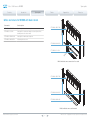
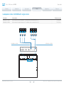
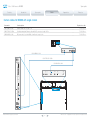
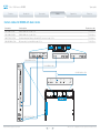
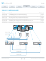
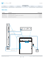
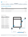
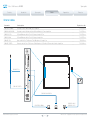
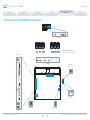
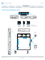
Cisco TelePresence MX800
Contents
Introduction
Spare parts
Cables
Appendices
Contact us
Spare parts
for Cisco TelePresence MX800
D15126.01 MX800 Spare parts, JULY 2014.
1
www.cisco.com — Copyright © 2014 Cisco Systems, Inc. All rights reserved.
Cisco TelePresence MX800
Contents
Introduction
Thank you for choosing Cisco!
Your Cisco product has been designed to give you many
years of safe, reliable operation.
This part of the product documentation is made to help
determine spare parts for order and replacement purposes.
Our main objective is to address your goals and needs.
Please let us know how well we succeeded!
May we recommend that you visit the Cisco web site
regularly for updated versions of this guide.
The user documentation can be found on
► http://www.cisco.com/go/mx-docs
How to use this guide
The top menu bar and the entries in the Table of contents are
all hyperlinks. You can click on them to go to the topic.
Spare parts
Spare parts
Cables
Appendices
Contact us
Table of contents
Introduction............................................................................. 3
Spare parts............................................................................. 5
Floor stand parts....................................................................... 6
Wall mount parts....................................................................... 7
Monitor, cameras, loudspeakers, codec and PoE injector....... 8
Grilles and covers for MX800 with single camera.................... 9
Grilles and covers for MX800 with dual camera..................... 10
Peripherals.............................................................................. 11
Cables................................................................................... 12
Loudspeaker cables for MX800 with single camera.............. 13
Loudspeaker cables for MX800 with dual camera................. 14
Camera cables for MX800 with single camera....................... 15
Camera cables for MX800 with dual camera......................... 16
Cables internal to the dual camera assembly......................... 17
Monitor cables........................................................................ 18
Power cables for monitors and PoE adapter.......................... 19
External cables....................................................................... 20
Appendices........................................................................... 21
Connector locations for MX800 with single camera.............. 22
Connector locations for MX800 with dual camera................. 23
Cisco contacts...................................................................... 24
D15126.01 MX800 Spare parts, JULY 2014.
2
www.cisco.com — Copyright © 2014 Cisco Systems, Inc. All rights reserved.
Cisco TelePresence MX800
Contents
Introduction
Introduction
Spare parts
Spare parts
Cables
Appendices
Contact us
Chapter 1
Introduction
D15126.01 MX800 Spare parts, JULY 2014.
3
www.cisco.com — Copyright © 2014 Cisco Systems, Inc. All rights reserved.
Cisco TelePresence MX800
Contents
Products covered in this guide:
• Cisco TelePresence MX800
Introduction
Introduction
Spare parts
Spare parts
Cables
This guide lists all spare parts and cables that may be
ordered for Cisco TelePresence MX800. Part numbers are
included for all items.
The guide covers both MX800 with single camera and MX800
with dual camera (speaker track). All mounting options are
covered.
Note that you cannot upgrade a single camera system to a
dual camera system by ordering spare parts; you must order
a complete system.
Appendices
Contact us
User documentation
The user documentation for the Cisco TelePresence systems
running the TC software includes several guides suitable for
various user groups.
We recommend you visit the Cisco web site regularly for
updated versions of the user documentation. Go to:
► http://www.cisco.com/go/mx-docs
Ordering information
To place an order, please contact your local Cisco
representative or Cisco partner and refer to part numbers as
listed in this document.
Cisco Service and Support
Cisco and our partners provide a broad portfolio of smart,
personalized services and support. For more information
about these services, go to:
► http://www.cisco.com/go/telepresenceservices
D15126.01 MX800 Spare parts, JULY 2014.
4
www.cisco.com — Copyright © 2014 Cisco Systems, Inc. All rights reserved.
Cisco TelePresence MX800
Contents
Introduction
Spare parts
Spare
Spare parts
parts
Cables
Appendices
Contact us
Chapter 2
Spare parts
D15126.01 MX800 Spare parts, JULY 2014.
5
www.cisco.com — Copyright © 2014 Cisco Systems, Inc. All rights reserved.
Cisco TelePresence MX800
Contents
Introduction
Spare parts
Spare
Spare parts
parts
Cables
Appendices
Contact us
Floor stand parts
Part number
Part description
CTS-MX800-S-FSK=
Floor stand kit (all stand parts for both free standing and wall
secured options are included)
CTS-MX-FSK-SKI=
Feet for free standing floor stand. This is only the feet; it is
not the complete frame. The feet are also included in the floor
stand kit (CTS-MX800-S-FSK=)
Note: If you have a wall mounted MX800, you have to order the following parts in
order to change to one of the floor standing options:
• Floor stand kit (CTS-MX800-S-FSK=), see illustration to the right.
• Lower grille (CTS-MX800-S-LGR=), see “Grilles and covers for MX800 with single
camera” on page 9 or “Grilles and covers for MX800 with dual camera” on
page 10.
CTS-MX-FSK-SKI=
CTS-MX800-S-FSK=
D15126.01 MX800 Spare parts, JULY 2014.
6
www.cisco.com — Copyright © 2014 Cisco Systems, Inc. All rights reserved.
Cisco TelePresence MX800
Contents
Introduction
Spare parts
Spare
Spare parts
parts
Cables
Appendices
Contact us
Wall mount parts
Part number
Part description
CTS-MX800-S-WMK=
Wall mount kit
Note: If you have an MX800 that is mounted on a floor stand, you have to order the
following parts in order to change to the wall mounted option:
• Wall mount kit (CTS-MX800-S-WMK=), see illustration to the right.
• Lower grille (CTS-MX800-SWM-LGR=), see “Grilles and covers for MX800 with
single camera” on page 9 or “Grilles and covers for MX800 with dual camera”
on page 10.
CTS-MX800-S-WMK=
D15126.01 MX800 Spare parts, JULY 2014.
7
www.cisco.com — Copyright © 2014 Cisco Systems, Inc. All rights reserved.
Cisco TelePresence MX800
Contents
Introduction
Spare parts
Spare
Spare parts
parts
Cables
Appendices
Contact us
Monitor, cameras, loudspeakers, codec and PoE injector
Part number
Part description
CTS-MXCAM-S=
Single camera
CTS-MXCAM-D=
Dual camera assembly
CTS-MXCODEC=
Codec
CTS-MX700800-SPKR=
One loudspeaker (fits in all positions)
CTS-PWR-AIR-INJ5=
Power over Ethernet (PoE) injector (without cables)
CTS-MX800-MON-S-S=
Monitor for single camera system (without camera, codec,
loudspeakers, PoE injector, covers, grilles and cables)
CTS-MX800-MON-S-D=
Monitor for dual camera system (without camera, codec,
loudspeakers, PoE injector, covers, grilles and cables)
CTS-MXCODEC=
CTS-MX700800-SPKR=
CTS-MXCAM-S=
CTS-MX800-MON-S-S=
CTS-PWR-AIR-INJ5=
MX800 with single camera
CTS-MXCODEC=
CTS-MX700800-SPKR=
CTS-MXCAM-D=
CTS-MX800-MON-S-D=
CTS-PWR-AIR-INJ5=
MX800 with dual camera
D15126.01 MX800 Spare parts, JULY 2014.
8
www.cisco.com — Copyright © 2014 Cisco Systems, Inc. All rights reserved.
Cisco TelePresence MX800
Contents
Introduction
Spare parts
Spare
Spare parts
parts
Cables
Appendices
Contact us
Grilles and covers for MX800 with single camera
Part number
Part description
CTS-MX800-SSC-TGR=
Speaker grille for single camera systems
CTS-MX800-S-LGR=
Lower grille for systems mounted on a stand (for both free
standing and secured to the wall)
CTS-MX800-SWM-LGR=
Lower grille for wall mounted systems
CTS-MX800-MON-SCV=
Left and right side covers
CTS-MX800-SSC-TGR=
CTS-MX800-MON-SCV=
CTS-MX800-S-LGR=
MX800 with single camera, mounted on floor stand
CTS-MX800-SSC-TGR=
CTS-MX800-MON-SCV=
CTS-MX800-SWM-LGR=
MX800 with single camera, wall mounted
D15126.01 MX800 Spare parts, JULY 2014.
9
www.cisco.com — Copyright © 2014 Cisco Systems, Inc. All rights reserved.
Cisco TelePresence MX800
Contents
Introduction
Spare parts
Spare
Spare parts
parts
Cables
Appendices
Contact us
Grilles and covers for MX800 with dual camera
Part number
Part description
CTS-MX800-SDC-TGR=
Speaker grille for dual camera systems
CTS-MX800-S-LGR=
Lower grille for systems mounted on a stand (for both free
standing and secured to the wall)
CTS-MX800-SWM-LGR=
Lower grille for wall mounted systems
CTS-MX800-MON-SCV=
Left and right side covers
CTS-MX800-SDC-TGR=
CTS-MX800-MON-SCV=
CTS-MX800-S-LGR=
MX800 with dual camera, mounted on floor stand
CTS-MX800-SDC-TGR=
CTS-MX800-MON-SCV=
CTS-MX800-SWM-LGR=
MX800 with dual camera, wall mounted
D15126.01 MX800 Spare parts, JULY 2014.
10
www.cisco.com — Copyright © 2014 Cisco Systems, Inc. All rights reserved.
Cisco TelePresence MX800
Contents
Spare parts
Introduction
Spare
Spare parts
parts
Cables
Appendices
Contact us
Peripherals
Part number
Part description
CTS-CTRL-DV10=
Cisco TelePresence Touch 10 without cables
CTS-MIC-TABL60=
Cisco TelePresence Table Microphone 60 with cable. Length: 9 m
CAB-MIC-T60EXT=
Extension cable for Cisco TelePresence Table Microphone 60. Euroblock 3.5 mm, male to female. Length: 9 m
CTS-MIC-CLNG=
Cisco Ceiling Mic Audio Science with cables and standard mounting kit
CTS-MTKIT-UA=
Universal mounting kit for Cisco Ceiling Mic Audio Science
D15126.01 MX800 Spare parts, JULY 2014.
11
www.cisco.com — Copyright © 2014 Cisco Systems, Inc. All rights reserved.
Cisco TelePresence MX800
Contents
Introduction
Spare parts
Cables
Spare parts
Appendices
Contact us
Chapter 3
Cables
D15126.01 MX800 Spare parts, JULY 2014.
12
www.cisco.com — Copyright © 2014 Cisco Systems, Inc. All rights reserved.
Cisco TelePresence MX800
Contents
Spare parts
Introduction
Cables
Spare parts
Appendices
Contact us
Loudspeaker cables for MX800 with single camera
Part number
Part description
ID printed on cable
CAB-MX800-L-SPKR=
Cable assembly for the left loudspeakers. The individual cables are numbered from 1 to 3
72-100632-xx
CAB-MX800-R-SPKR=
Cable assembly for the right loudspeakers. The individual cables are numbered from 4 to 6
72-100633-xx
1
2
3
4
5
6
CAB-MX800-L-SPKR=
CAB-MX800-R-SPKR=
HDMI
COLOR
CALIBRATION
CAMERA
POWER
HDMI
D15126.01 MX800 Spare parts, JULY 2014.
CAMERA
POWER
COLOR
CALIBRATION
2
2
1
1
13
www.cisco.com — Copyright © 2014 Cisco Systems, Inc. All rights reserved.
Cisco TelePresence MX800
Contents
Spare parts
Introduction
Cables
Spare parts
Appendices
Contact us
Loudspeaker cables for MX800 with dual camera
Part number
Part description
ID printed on cable
CAB-MX800-L-SPKR=
Cable assembly for the left loudspeakers. The individual cables are numbered from 1 to 3
72-100632-xx
CAB-MX800-R-SPKR=
Cable assembly for the right loudspeakers. The individual cables are numbered from 4 to 6
72-100633-xx
1
2
3
5
4
6
(not used)
CAB-MX800-L-SPKR=
CAB-MX800-R-SPKR=
HDMI
COLOR
CALIBRATION
CAMERA
POWER
HDMI
D15126.01 MX800 Spare parts, JULY 2014.
CAMERA
POWER
COLOR
CALIBRATION
2
2
1
1
14
www.cisco.com — Copyright © 2014 Cisco Systems, Inc. All rights reserved.
Cisco TelePresence MX800
Contents
Spare parts
Introduction
Cables
Spare parts
Appendices
Contact us
Camera cables for MX800 with single camera
Part number
Part description
ID printed on cable
CAB-2HDMILK-1.6M=
HDMI to HDMI cable. Length: 1.6 m
72-100636-xx
CAB-ETHRJ45-1.85M=
Shielded, twisted pair Ethernet cable with RJ45 connectors. Length: 1.85 m
72-100644-xx
CAB-DIN-BRL-0.4M=
DC power cable, 4-pin mini-DIN to 2 mm Barrel. Length: 0.4 m
72-100654-xx
DAISY
CHAIN
VISCA
3
DAISY
CHAIN
VISCA
3
CAB-2HDMILK-1.6M=
CAB-ETHRJ45-1.85M=
CAB-DIN-BRL-0.4M=
COLOR
CALIBRATION
CAMERA
POWER
HDMI
HDMI
D15126.01 MX800 Spare parts, JULY 2014.
15
CAMERA
POWER
COLOR
CALIBRATION
2
2
1
1
www.cisco.com — Copyright © 2014 Cisco Systems, Inc. All rights reserved.
Cisco TelePresence MX800
Contents
Spare parts
Introduction
Cables
Spare parts
Appendices
Contact us
Camera cables for MX800 with dual camera
Part number
Part description
ID printed on cable
CAB-2HDMILK-1.4M=
HDMI to HDMI cable. Length: 1.4 m
72-100637-xx
CAB-2HDMILK-1.85M=
HDMI to HDMI cable. Length: 1.85 m
72-100638-xx
CAB-ETHRJ45-1.05M=
Shielded, twisted pair Ethernet cable with RJ45 connectors. Length: 1.05 m
72-100642-xx
CAB-2DC4MIN-0.65M=
DC power cable, 4-pin mini-DIN. Length: 0.65 m
72-100656-xx
1
1
2
1
2
1
2
1
2
1
2
1
2
1
DAISY
CHAIN
2
VISCA
DAISY
CHAIN
3
DAISY
CHAIN
2
VISCA
VISCA
3
DAISY
CHAIN
3
VISCA
3
CAB-2HDMILK-1.85M=
CAB-2HDMILK-1.4M=
CAB-2DC4MIN-0.65M=
COLOR
CALIBRATION
CAMERA
POWER
HDMI
HDMI
CAMERA
POWER
COLOR
CALIBRATION
2
2
1
1
CAB-ETHRJ45-1.05M=
D15126.01 MX800 Spare parts, JULY 2014.
16
www.cisco.com — Copyright © 2014 Cisco Systems, Inc. All rights reserved.
Cisco TelePresence MX800
Contents
Spare parts
Introduction
Cables
Spare parts
Appendices
Contact us
Cables internal to the dual camera assembly
Part number
Part description
ID printed on cable
CAB-2DC-BRL-0.6M=
DC power cable with Barrel Plug. For use in the dual camera assembly. Length: 0.6 m
72-100613-xx
CAB-2DC-BRL-1.15M=
DC power cable with Barrel Plug. For use in the dual camera assembly. Length: 1.15 m
72-100614-xx
CAB-MIC-RJ.5-0.5M=
Bundle of two RJ.5 microphone cables. For use in the dual camera assembly. Length: 0.5 m
72-100678-xx
CAB-MIC-RJ.5-1.0M=
Bundle of two RJ.5 microphone cables. For use in the dual camera assembly. Length: 1.0 m
72-100679-xx
CAB-ETHRJ45-0.7M=
Shielded, twisted pair Ethernet cable with RJ45 connectors. For use in the dual camera assembly. Length: 0.7 m
72-100616-xx
CAB-ETHRJ45-1.2M=
Shielded, twisted pair Ethernet cable with RJ45 connectors. For use in the dual camera assembly. Length: 1.2 m
72-100617-xx
1
1
2
1
2
1
2
1
1
2
DAISY
CHAIN
2
VISCA
2
DAISY
CHAIN
3
VISCA
3
CAB-MIC-RJ.5-1.0M=
CAB-MIC-RJ.5-0.5M=
1
1
2
1 2
1
2
1
2
2
1 2
1
2
1
2
1
2
1
DAISY
CHAIN
2
VISCA
3
DAISY
CHAIN
VISCA
3
CAB-2DC-BRL-1.15M=
CAB-2DC-BRL-0.6M=
CAB-ETHRJ45-1.2M=
CAB-ETHRJ45-0.7M=
D15126.01 MX800 Spare parts, JULY 2014.
17
www.cisco.com — Copyright © 2014 Cisco Systems, Inc. All rights reserved.
Cisco TelePresence MX800
Contents
Introduction
Spare parts
Cables
Spare parts
Appendices
Contact us
Monitor cables
Part number
Part description
ID printed on cable
CAB-2HDMILK-1.20M=
HDMI to HDMI cable. Length: 1.20 m
72-100634-xx
CAB-ETHRJ45-2.6M=
Shielded, twisted pair Ethernet cable with RJ45 connectors. Length: 2.6 m
72-100646-xx
CAB-USB-A-B-1.45M=
USB A to USB B cable. Length: 1.45 m
72-100648-xx
COLOR
CALIBRATION
CAMERA
POWER
HDMI
2
1
CAB-2HDMILK-1.20M=
CAB-USB-A-B-1.45M=
HDMI
CAMERA
POWER
COLOR
CALIBRATION
2
1
AP (
CAB-ETHRJ45-2.6M=
D15126.01 MX800 Spare parts, JULY 2014.
) SWITCH (
)
AP (
18
) SWITCH (
)
www.cisco.com — Copyright © 2014 Cisco Systems, Inc. All rights reserved.
Cisco TelePresence MX800
Contents
Introduction
Spare parts
Cables
Spare parts
Appendices
Contact us
Power cables for monitors and PoE adapter
Part number
Part description
ID printed on cable
PWR-CAB-INT-0.6M=
Power extension cord for all countries except China. Length: 0.6 m
37-100706-xx
PWR-CAB-INT-1.4M=
Power extension cord for all countries except China. Length: 1.4 m
37-100711-xx
PWR-CAB-CHN-0.6M=
Power extension cord for China. Length: 0.6 m
37-100708-xx
PWR-CAB-CHN-1.4M=
Power extension cord for China. Length: 1.4 m
37-100712-xx
Region-specific power cables
Part number
Part description
PWR-CORD-US-D=
Power cable US
PWR-CORD-EUR-D=
Power cable Europe
PWR-CORD-ARG-D=
Power cable Argentina
PWR-CORD-UK-D=
Power cable UK
PWR-CORD-CN-D=
Power cable China
PWR-CORD-ROK-D=
Power cable Korea
PWR-CORD-JPN-D=
Power cable Japan
PWR-CORD-CH-D=
Power cable Switzerland
PWR-CORD-BRA-D=
Power cable Brazil
PWR-CORD-AUS-D=
Power cable Australia
PWR-CORD-IND-D=
Power cable India
PWR-CORD-ZAF-D=
Power cable South-Africa
PWR-CAB-INT-0.6M= /
PWR-CAB-CHN-0.6M=
PWR-CAB-INT-1.4M= /
PWR-CAB-CHN-1.4M=
D15126.01 MX800 Spare parts, JULY 2014.
19
Region-specific power cable,
see table.
Power
• 100-240 VAC
• 50/60 Hz
www.cisco.com — Copyright © 2014 Cisco Systems, Inc. All rights reserved.
Cisco TelePresence MX800
Contents
Introduction
Spare parts
Cables
Spare parts
Appendices
Contact us
External cables
Part number
Part description
ID printed on cable
CAB-PRESO-2HDMI=
Presentation cable, HDMI to HDMI, grey. Length: 8 m
72-100727-xx
CAB-DVI-VGA-PHOEN=
Presentation cable, VGA and mini-jack to DVI and Euroblock 3.5 mm. Length: 8 m
72-100726-xx
CAB-DV10-12.5=
PoE rated Ethernet cable for Touch 10, flat, grey. Length: 12.5 m
72-100706-xx
CAB-DV10-4M=
PoE rated Ethernet cable for Touch 10, flat, grey. Length: 4 m
72-100707-xx
CAB-MIC-T60=
Spare cable for Cisco TelePresence Table Microphone 60. Length: 9 m
74-101341-xx
CAB-MIC-T60EXT=
Extension cable for Cisco TelePresence Table Microphone 60. Euroblock 3.5 mm, male to female. Length: 9 m
74-100624-xx
CAB-MIC-T60=
AP (
) SWITCH (
)
AP (
) SWITCH (
)
CAB-MIC-T60EXT=
CAB-DVI-VGA-PHOEN=
CAB-DV10-4M= /
CAB-DV10-12.5=
CAB-PRESO-2HDMI=
D15126.01 MX800 Spare parts, JULY 2014.
20
www.cisco.com — Copyright © 2014 Cisco Systems, Inc. All rights reserved.
Cisco TelePresence MX800
Contents
Introduction
Spare parts
Spare parts
Cables
Appendices
Appendices
Contact us
Chapter 4
Appendices
D15126.01 MX800 Spare parts, JULY 2014.
21
www.cisco.com — Copyright © 2014 Cisco Systems, Inc. All rights reserved.
Cisco TelePresence MX800
Contents
Spare parts
Introduction
Spare parts
Appendices
Appendices
Cables
Contact us
Connector locations for MX800 with single camera
DAISY
CHAIN
VISCA
3
DAISY
CHAIN
VISCA
3
Camera
}
Loudspeaker connectors
(rear side of each loudspeaker)
Codec
HDMI
COLOR
CALIBRATION
CAMERA
POWER
2
1
Monitor
HDMI
CAMERA
POWER
Power in
(PoE injector)
COLOR
CALIBRATION
2
1
AP (
) SWITCH (
)
AP (
) SWITCH (
)
Network
(PoE injector)
Power in
D15126.01 MX800 Spare parts, JULY 2014.
Power out
22
www.cisco.com — Copyright © 2014 Cisco Systems, Inc. All rights reserved.
Cisco TelePresence MX800
Contents
Spare parts
Introduction
Cables
Spare parts
Appendices
Contact us
Connector locations for MX800 with dual camera
1
1
2
1
2
1
2
1
2
1
2
1
2
1
DAISY
CHAIN
2
VISCA
DAISY
CHAIN
3
DAISY
CHAIN
2
Camera assembly board
VISCA
VISCA
3
DAISY
CHAIN
3
Left camera board
VISCA
3
Right camera board
}
Loudspeaker connectors
(rear side of each loudspeaker)
Codec
HDMI
COLOR
CALIBRATION
CAMERA
POWER
2
1
Monitor
HDMI
CAMERA
POWER
Power in
(PoE injector)
COLOR
CALIBRATION
2
1
AP (
) SWITCH (
)
AP (
) SWITCH (
)
Network
(PoE injector)
Power in
D15126.01 MX800 Spare parts, JULY 2014.
Power out
23
www.cisco.com — Copyright © 2014 Cisco Systems, Inc. All rights reserved.
Cisco TelePresence MX800
Contents
Introduction
Spare parts
Spare parts
Cables
Appendices
Contact us
Intellectual property rights
THE SPECIFICATIONS AND INFORMATION REGARDING THE
PRODUCTS IN THIS MANUAL ARE SUBJECT TO CHANGE
WITHOUT NOTICE. ALL STATEMENTS, INFORMATION, AND
RECOMMENDATIONS IN THIS MANUAL ARE BELIEVED TO BE
ACCURATE BUT ARE PRESENTED WITHOUT WARRANTY OF
ANY KIND, EXPRESS OR IMPLIED. USERS MUST TAKE FULL
RESPONSIBILITY FOR THEIR APPLICATION OF ANY PRODUCTS.
THE SOFTWARE LICENSE AND LIMITED WARRANTY FOR THE
ACCOMPANYING PRODUCT ARE SET FORTH IN THE INFORMATION
PACKET THAT SHIPPED WITH THE PRODUCT AND ARE
INCORPORATED HEREIN BY THIS REFERENCE. IF YOU ARE UNABLE
TO LOCATE THE SOFTWARE LICENSE OR LIMITED WARRANTY,
CONTACT YOUR CISCO REPRESENTATIVE FOR A COPY.
The Cisco implementation of TCP header compression is an
adaptation of a program developed by the University of California,
Berkeley (UCB) as part of UCB’s public domain version of the UNIX
operating system. All rights reserved. Copyright © 1981, Regents of
the University of California.
NOTWITHSTANDING ANY OTHER WARRANTY HEREIN, ALL
DOCUMENT FILES AND SOFTWARE OF THESE SUPPLIERS ARE
PROVIDED “AS IS” WITH ALL FAULTS. CISCO AND THE ABOVENAMED SUPPLIERS DISCLAIM ALL WARRANTIES, EXPRESSED
OR IMPLIED, INCLUDING, WITHOUT LIMITATION, THOSE OF
MERCHANTABILITY, FITNESS FOR A PARTICULAR PURPOSE AND
NONINFRINGEMENT OR ARISING FROM A COURSE OF DEALING,
USAGE, OR TRADE PRACTICE.
Cisco contacts
On our web site you will find an overview of the worldwide Cisco contacts.
Go to: ► http://www.cisco.com/go/offices
Corporate Headquarters
Cisco Systems, Inc.
170 West Tasman Dr.
San Jose, CA 95134 USA
IN NO EVENT SHALL CISCO OR ITS SUPPLIERS BE LIABLE FOR ANY
INDIRECT, SPECIAL, CONSEQUENTIAL, OR INCIDENTAL DAMAGES,
INCLUDING, WITHOUT LIMITATION, LOST PROFITS OR LOSS OR
DAMAGE TO DATA ARISING OUT OF THE USE OR INABILITY TO
USE THIS MANUAL, EVEN IF CISCO OR ITS SUPPLIERS HAVE BEEN
ADVISED OF THE POSSIBILITY OF SUCH DAMAGES.
Cisco and the Cisco Logo are trademarks of Cisco Systems, Inc. and/
or its affiliates in the U.S. and other countries. A listing of Cisco’s
trademarks can be found at www.cisco.com/go/trademarks. Third
party trademarks mentioned are the property of their respective
owners. The use of the word partner does not imply a partnership
relationship between Cisco and any other company. (1005R)
Any Internet Protocol (IP) addresses and phone numbers used in
this document are not intended to be actual addresses and phone
numbers. Any examples, command display output, network topology
diagrams, and other figures included in the document are shown for
illustrative purposes only. Any use of actual IP addresses or phone
numbers in illustrative content is unintentional and coincidental.
TANDBERG is now a part of Cisco. TANDBERG® is a registered
trademark belonging to Tandberg ASA.
D15126.01 MX800 Spare parts, JULY 2014.
24
www.cisco.com — Copyright © 2014 Cisco Systems, Inc. All rights reserved.