1
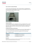
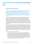
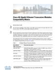
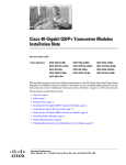
Cisco SFP and SFP+ Transceiver Module
Installation Notes
Revised: September 13, 2012
Product Numbers:
SFP-10G-SR=
SFP-10G-LR=
SFP-10G-LRM=
SFP-OC48-LR2=
SFP-GE-Z=
SFP-OC3-MM=
SFP-OC3-SR=
SFP-OC12-LR2=
SFP-OC3-LR2=
SFP-GE-L=
SFP-OC12-SR=
GLC-SX-MM-RGD=
SFP-OC3-LR1=
SFP-OC48-SR=
SFP-OC48-IR1=
GLC-ZX-SM-RGD=
SFP-GE-S=
GLC-SX-MM=
SFP-OC3-IR1=
GLC-FE-100FX=
GLC-ZX-SM=
SFP-OC12-IR1=
GLC-T=
GLC-FE-100FX-RGD=
GLC-LH-SM=
GLC-BX-D=
GLC-BX-U=
GLC-FE-100BX-D=
GLC-FE-100BX-U=
GLC-FE-100EX=
GLC-FE-100LX=
GLC-FE-100ZX=
SFP-H10GB-CU1M=
SFP-H10GB-CU3M=
SFP-H10GB-CU5M=
SFP-10G-ER=
SFP-OC12-MM=
DWDM-SFP-xxxx=
SFP-OC12-LR1=
CWDM-SFP-xxxx=
GLC-LX-SM-RGD=
GLC-GE-100FX=
GLC-FE-100LX-RGD=
GLC-EX-SMD=
SFP-H10GB-ACU7M= SFP-H10GB-ACU10M=
GLC-SX-MMD=
GLC-LH-SMD=
GLC-2BX-D=
SFP-10G-SR-X=
SFP-10G-LR-X=
SFP-10G-ZR=
SFP-H10GB-CU1-5M= SFP-H10GB-CU2M=
SFP-H10GB-CU2-5M= SFP-10G-AOC1=
SFP-10G-AOC2M=
SFP-10G-AOC3M=
SFP-10G-AOC5M=
SFP-10G-AOC10M=
DWDM-SFP10G-xx.xx= GLC-ZX-SMD=
SFP-10G-AOC7M=
This installation note provides the installation instructions for the Cisco small form-factor pluggable
(SFP) and SFP+ transceiver modules. These transceiver modules are hot-swappable input/output (I/O)
devices that plug into 100BASE, 1000BASE and 10GBASE ports (for SFP+), which connect the module
port with the fiber-optic or copper network.
Americas Headquarters:
Cisco Systems, Inc., 170 West Tasman Drive, San Jose, CA 95134-1706 USA
Contents
Contents
This document contains these sections:
•
Overview, page 2
•
Safety, page 17
•
Required Tools, page 22
•
Installing SFP and SFP+ Transceiver Modules, page 23
•
Removing SFP and SFP+ Transceiver Modules, page 28
•
Obtaining Documentation and Submitting a Service Request, page 36
Overview
The SFP transceiver modules are hot-pluggable I/O devices that plug into module sockets. The
transceiver connects the electrical circuitry of the module with the optical or copper network.
You can use any combination of SFP transceiver modules that your Cisco device supports. The only
restrictions are that each port must match the wavelength specifications on the other end of the cable and
that the cable must not exceed the stipulated cable length for reliable communications.
Use only Cisco SFP transceiver modules on your Cisco device. Each SFP transceiver module supports
the Cisco Quality Identification (ID) feature which allows a Cisco switch or router to identify and
validate that the transceiver module is certified and tested by Cisco.
An optical SFP transceiver module is shown in Figure 1.
SFP Transceiver Module (Fiber-Optic LC Connector)
G
1 L
C
L 21 -S
N
S # CF X
/N 50 R -M
: 7 10 M
O / 4 C
H 01 0 la
1 .1 s
2
3 0 s
3
4
5
6 0
3
-1
3
Figure 1
Receive optical bore
Transmit optical bore
Bail clasp
Note
130927
Dust plug
SFP transceiver modules that operate with single-strand SMF, have only one optical bore; the other bore
is blocked off.
Cisco SFP and SFP+ Transceiver Module Installation Notes
2
78-15160-07
Overview
A copper SFP transceiver module in shown in Figure 2.
1000BASE-T SFP Transceiver Module (RJ-45 Connector)
87922
Figure 2
An SFP+ transceiver module is shown in Figure 3.
G
1
331875
SFP+ Transceiver Module (Fiber-Optic LC Connector)
1 L
C
L 21 -S
N
S # CF X
/N 50 R -M
: 7 10 M
O / 4 C
H 01 0 la
1 .1 s
2
3 0 s
3
4
5
6 0
3
-1
3
Figure 3
4
3
2
1
Dust plug
3
Transmit bore
2
Bail clasp with clasp tab
4
Receive bore
The product numbers and brief description of the SFP and SFP+ transceiver modules are listed in
Table 1.
Table 1
Product Numbers and Descriptions
SFP Transceiver Module
Product Number
Transceiver Description
10-Gigabit Ethernet
SFP-10G-SR
Cisco 10GBASE-SR SFP+ transceiver module for MMF, 850-nm wavelength
SFP-10G-SR-X
Cisco 10GBASE-SR SFP+ transceiver module for MMF, 850-nm wavelength, extended
temperature range
SFP-10G-LR
Cisco 10GBASE-LR SFP+ transceiver module for SMF, 1310-nm wavelength
SFP-10G-LR-X
Cisco multirate 10GBASE-LR/10GBASE-LW/OTU2e SFP+ transceiver module for SMF,
1310-nm wavelength, extended temperature range
SFP-10G-LRM
Cisco 10GBASE-LRM SFP+ transceiver module for MMF and SMF, 1310-nm wavelength
SFP-10G-ER
Cisco 10GBASE-ER SFP+ transceiver module for SMF, 1550-nm wavelength
SFP-10G-ZR
Cisco 10GBASE-ZR SFP+ transceiver module for SMF, 1550-nm wavelength
Cisco SFP and SFP+ Transceiver Module Installation Notes
78-15160-07
3
Overview
Table 1
Product Numbers and Descriptions (continued)
SFP Transceiver Module
Product Number
Transceiver Description
SFP-H10GB-CU1M
Cisco 10GBASE-CU passive Twinax SFP+ cable assembly, 1 meter
SFP-H10GB-CU1-5M
Cisco 10GBASE-CU passive Twinax SFP+ cable assembly, 1.5 meters
SFP-H10GB-CU2M
Cisco 10GBASE-CU passive Twinax SFP+ cable assembly, 2 meters
SFP-H10GB-CU2-5M
Cisco 10GBASE-CU passive Twinax SFP+ cable assembly, 2.5 meters
SFP-H10GB-CU3M
Cisco 10GBASE-CU passive Twinax SFP+ cable assembly, 3 meters
SFP-H10GB-CU5M
Cisco 10GBASE-CU passive Twinax SFP+ cable assembly, 5 meters
SFP-H10GB-ACU7M
Cisco 10GBASE-CU active Twinax SFP+ cable assembly, 7 meters
SFP-H10GB-ACU10M
Cisco 10GBASE-CU active Twinax SFP+ cable assembly, 10 meters
SFP-10G-AOC1M
Cisco 10GBASE-AOC Active Optical Cable SFP+ assembly, 1 meter
SFP-10G-AOC2M
Cisco 10GBASE-AOC Active Optical Cable SFP+ assembly, 2 meters
SFP-10G-AOC3M
Cisco 10GBASE-AOC Active Optical Cable SFP+ assembly, 3 meters
SFP-10G-AOC5M
Cisco 10GBASE-AOC Active Optical Cable SFP+ assembly, 5 meters
SFP-10G-AOC7M
Cisco 10GBASE-AOC Active Optical Cable SFP+ assembly, 7 meters
SFP-10G-AOC10M
Cisco 10GBASE-AOC Active Optical Cable SFP+ assembly, 10 meters
1-Gigabit Ethernet
GLC-SX-MM=
Cisco 1000BASE-SX SFP transceiver module for MMF, 850-nm wavelength,
commercial operating temperature range.
GLC-SX-MM-RGD=
Cisco 1000BASE-SX SFP transceiver module for MMF, 850-nm wavelength,
industrial operating temperature range.
SFP-GE-S=
Cisco 1000BASE-SX SFP transceiver module for MMF, 850-nm wavelength,
extended operating temperature range.
GLC-SX-MMD=
Cisco 1000BASE-SX SFP transceiver module for MMF, 850-nm wavelength,
extended operating temperature range.
GLC-LH-SM=
Cisco 1000BASE-LX/LH SFP transceiver module for MMF and SMF, 1300-nm wavelength,
commercial operating temperature range.
GLC-LX-SM-RGD=
Cisco 1000BASE-LX/LH SFP transceiver module for MMF and SMF, 1300-nm wavelength,
industrial operating temperature range.
SFP-GE-L=
Cisco 1000BASE-LX/LH SFP transceiver module for MMF and SMF, 1300-nm wavelength,
extended operating temperature range.
GLC-LH-SMD=
Cisco 1000BASE-LX/LH SFP transceiver module for MMF and SMF, 1300-nm wavelength,
extended operating temperature range.
GLC-EX-SMD=
Cisco 1000BASE-EX SFP transceiver module for SMF, 1310-nm wavelength, extended
operating temperature range.
GLC-ZX-SM=
Cisco 1000BASE-ZX SFP transceiver module for SMF, 1550-nm wavelength,
commercial operating temperature range.
GLC-ZX-SM-RGD=
Cisco 1000BASE-ZX SFP transceiver module for SMF, 1550-nm wavelength,
industrial operating temperature range.
SFP-GE-Z=
Cisco 1000BASE-ZX SFP transceiver module for SMF, 1550-nm wavelength,
extended operating temperature range.
Cisco SFP and SFP+ Transceiver Module Installation Notes
4
78-15160-07
Overview
Table 1
Product Numbers and Descriptions (continued)
SFP Transceiver Module
Product Number
Transceiver Description
GLC-ZX-SMD=
Cisco 1000BASE-ZX SFP transceiver module for SMF, 1550-nm wavelength, extended
operating temperature range.
GLC-T=
1000BASE-T SFP transceiver module for copper networks,
commercial operating temperature range.
SFP-GE-T=
1000BASE-T SFP transceiver module for copper networks,
extended operating temperature range.
GLC-BX-D=
1000BASE-BX10 SFP module for single-strand SMF, 1490-nm TX/1310-nm RX wavelength,
commercial operating temperature range.
GLC-BX-U=
1000BASE-BX10 SFP module for single-strand SMF, 1310-nm TX/1490-nm RX wavelength,
commercial operating temperature range.
GLC-2BX-D=
Dual-channel 1000BASE-BX10 SFP module for single-strand SMF, 1490-nm TX/1310-nm RX
wavelength, commercial operating temperature range.
Fast Ethernet
GLC-FE-100FX=
100BASE-FX SFP module for 100-Mb ports, MMF, 1310-nm wavelength,
commercial operating temperature range.
GLC-FE-100FX-RGD=
100BASE-FX SFP module for 100-Mb ports, MMF, 1310-nm wavelength,
industrial operating temperature range.
GLC-GE-100FX=
100BASE-FX SFP module for Gigabit Ethernet ports, MMF, 1310-nm wavelength,
commercial operating temperature range.
GLC-FE-100LX=
100BASE-LX10 SFP module for 100-Mb ports, SMF, 1310-nm wavelength,
commercial operating temperature range.
GLC-FE-100LX-RGD=
100BASE-LX10 SFP module for 100-Mb ports, SMF, 1310-nm wavelength,
industrial operating temperature range.
GLC-FE-100BX-D=
100BASE-BX10-D SFP module for single-strand SMF, 1550-nm TX/1310-nm RX wavelength,
commercial operating temperature range.
GLC-FE-100BX-U=
100BASE-BX10-U SFP module for single-strand SMF, 1310-nm TX/1550-nm RX wavelength,
commercial operating temperature range.
GLC-FE-100EX=
100BASE-EX SFP module for 100-Mb ports, SMF, 1310-nm wavelength,
commercial operating temperature range.
GLC-FE-100ZX=
100BASE-ZX SFP module for 100-Mb ports, SMF, 1550-nm wavelength,
commercial operating temperature range.
Cisco SFP and SFP+ Transceiver Module Installation Notes
78-15160-07
5
Overview
Table 1
Product Numbers and Descriptions (continued)
SFP Transceiver Module
Product Number
Transceiver Description
SONET/SDH
SFP-OC3-MM
SFP OC-3/STM-1 Multimode
SFP-OC3-SR
SFP OC-3/STM-1 Short-Reach
SFP-OC3-IR1
SFP OC-3/STM-1 Intermediate-Reach
SFP-OC3-LR1
SFP OC-3/STM-1 Long-Reach (40 km)
SFP-OC3-LR2
SFP OC-3/STM-1 Long-Reach (80 km)
SFP-OC12-MM
SFP OC-12/STM-4 Multimode
SFP-OC12-SR
SFP OC-12/STM-4 Short-Reach
SFP-OC12-IR1
SFP OC-12/STM-4 Intermediate-Reach
SFP-OC12-LR1
SFP OC-12/STM-4 Long-Reach (40 km)
SFP-OC12-LR2
SFP OC-12/STM-4 Long-Reach (80 km)
SFP-OC48-SR
SFP OC-48/STM-16 Short-Reach
SFP-OC48-IR1
SFP OC-48/STM-16 Intermediate-Reach
SFP-OC48-LR2
SFP OC-48/STM-16 Long-Reach (80 km)
CWDM
(OC-12/STM4, 1-Gigabit Ethernet, 1-Gigabit Fiber Channel, 2-Gigabit Fiber Channel, OC-48/STM-16)
CWDM-SFP-1470=
Longwave 1470-nm laser, single mode
CWDM-SFP-1490=
Longwave 1490-nm laser, single mode
CWDM-SFP-1510=
Longwave 1510-nm laser, single mode
CWDM-SFP-1530=
Longwave 1530-nm laser, single mode
CWDM-SFP-1550=
Longwave 1550-nm laser, single mode
CWDM-SFP-1570=
Longwave 1570-nm laser, single mode
CWDM-SFP-1590=
Longwave 1590-nm laser, single mode
CWDM-SFP-1610=
Longwave 1610-nm laser, single mode
DWDM
(OC-12/STM4, 1-Gigabit Ethernet, 1-Gigabit Fibre Channel, 2-Gigabit Fibre Channel, OC-48/STM-16)
DWDM-SFP-6141=
Longwave 1561.42-nm laser (100-GHz ITU channel 20), single mode
DWDM-SFP-6061=
Longwave 1560.61-nm laser (100-GHz ITU channel 21), single mode
DWDM-SFP-5979=
Longwave 1559.79-nm laser (100-GHz ITU channel 22), single mode
DWDM-SFP-5898=
Longwave 1558.98-nm laser (100-GHz ITU channel 23), single mode
DWDM-SFP-5817=
Longwave 1558.17-nm laser (100-GHz ITU channel 24), single mode
DWDM-SFP-5736=
Longwave 1557.36-nm laser (100-GHz ITU channel 25), single mode
DWDM-SFP-5655=
Longwave 1556.55-nm laser (100-GHz ITU channel 26), single mode
DWDM-SFP-5575=
Longwave 1555.75-nm laser (100-GHz ITU channel 27), single mode
DWDM-SFP-5494=
Longwave 1554.94-nm laser (100-GHz ITU channel 28), single mode
DWDM-SFP-5413=
Longwave 1554.13-nm laser (100-GHz ITU channel 29), single mode
Cisco SFP and SFP+ Transceiver Module Installation Notes
6
78-15160-07
Overview
Table 1
Product Numbers and Descriptions (continued)
SFP Transceiver Module
Product Number
Transceiver Description
DWDM-SFP-5332=
Longwave 1553.33-nm laser (100-GHz ITU channel 30), single mode
DWDM-SFP-5252=
Longwave 1552.52-nm laser (100-GHz ITU channel 31), single mode
DWDM-SFP-5172=
Longwave 1551.72-nm laser (100-GHz ITU channel 32), single mode
DWDM-SFP-5092=
Longwave 1550.92-nm laser (100-GHz ITU channel 33), single mode
DWDM-SFP-5012=
Longwave 1550.12-nm laser (100-GHz ITU channel 34), single mode
DWDM-SFP-4931=
Longwave 1549.32-nm laser (100-GHz ITU channel 35), single mode
DWDM-SFP-4851=
Longwave 1548.51-nm laser (100-GHz ITU channel 36), single mode
DWDM-SFP-4772=
Longwave 1547.72-nm laser (100-GHz ITU channel 37), single mode
DWDM-SFP-4692=
Longwave 1546.92-nm laser (100-GHz ITU channel 38), single mode
DWDM-SFP-4612=
Longwave 1546.12-nm laser (100-GHz ITU channel 39), single mode
DWDM-SFP-4532=
Longwave 1545.32-nm laser (100-GHz ITU channel 40), single mode
DWDM-SFP-4453=
Longwave 1544.53-nm laser (100-GHz ITU channel 41), single mode
DWDM-SFP-4373=
Longwave 1543.73-nm laser (100-GHz ITU channel 42), single mode
DWDM-SFP-4294=
Longwave 1542.94-nm laser (100-GHz ITU channel 43), single mode
DWDM-SFP-4214=
Longwave 1542.14-nm laser (100-GHz ITU channel 44), single mode
DWDM-SFP-4134=
Longwave 1541.35-nm laser (100-GHz ITU channel 45), single mode
DWDM-SFP-4056=
Longwave 1540.56-nm laser (100-GHz ITU channel 46), single mode
DWDM-SFP-3977=
Longwave 1539.77-nm laser (100-GHz ITU channel 47), single mode
DWDM-SFP-3898=
Longwave 1538.98-nm laser (100-GHz ITU channel 48), single mode
DWDM-SFP-3819=
Longwave 1538.19-nm laser (100-GHz ITU channel 49), single mode
DWDM-SFP-3739=
Longwave 1537.40-nm laser (100-GHz ITU channel 50), single mode
DWDM-SFP-3661=
Longwave 1536.61-nm laser (100-GHz ITU channel 51), single mode
DWDM-SFP-3582=
Longwave 1535.82-nm laser (100-GHz ITU channel 52), single mode
DWDM-SFP-3504=
Longwave 1535.04-nm laser (100-GHz ITU channel 53), single mode
DWDM-SFP-3425=
Longwave 1534.25-nm laser (100-GHz ITU channel 54), single mode
DWDM-SFP-3346=
Longwave 1533.47-nm laser (100-GHz ITU channel 55), single mode
DWDM-SFP-3268=
Longwave 1532.68-nm laser (100-GHz ITU channel 56), single mode
DWDM-SFP-3190=
Longwave 1531.90-nm laser (100-GHz ITU channel 57), single mode
DWDM-SFP-3112=
Longwave 1531.12-nm laser (100-GHz ITU channel 58), single mode
DWDM-SFP-3033=
Longwave 1530.33-nm laser (100-GHz ITU channel 59), single mode
Cisco SFP and SFP+ Transceiver Module Installation Notes
78-15160-07
7
Overview
Table 1
Product Numbers and Descriptions (continued)
SFP Transceiver Module
Product Number
Transceiver Description
10-Gigabit DWDM SFP+ (10G LAN, 10G WAN, OTU2/OTU2e)
DWDM-SFP10G-61.41=
10GBASE-DWDM 1561.41-nm SFP+ (100-GHz ITU grid)
DWDM-SFP10G-60.61=
10GBASE-DWDM 1560.61-nm SFP+ (100-GHz ITU grid)
DWDM-SFP10G-59.79=
10GBASE-DWDM 1559.79-nm SFP+ (100-GHz ITU grid)
DWDM-SFP10G-58.98=
10GBASE-DWDM 1558.98-nm SFP+ (100-GHz ITU grid)
DWDM-SFP10G-58.17=
10GBASE-DWDM 1558.17-nm SFP+ (100-GHz ITU grid)
DWDM-SFP10G-57.36=
10GBASE-DWDM 1557.36-nm SFP+ (100-GHz ITU grid)
DWDM-SFP10G-56.55=
10GBASE-DWDM 1556.55-nm SFP+ (100-GHz ITU grid)
DWDM-SFP10G-55.75=
10GBASE-DWDM 1555.75-nm SFP+ (100-GHz ITU grid)
DWDM-SFP10G-54.94=
10GBASE-DWDM 1554.94-nm SFP+ (100-GHz ITU grid)
DWDM-SFP10G-54.13=
10GBASE-DWDM 1554.13-nm SFP+ (100-GHz ITU grid)
DWDM-SFP10G-53.33=
10GBASE-DWDM 1553.33-nm SFP+ (100-GHz ITU grid)
DWDM-SFP10G-52.52=
10GBASE-DWDM 1552.52-nm SFP+ (100-GHz ITU grid)
DWDM-SFP10G-51.72=
10GBASE-DWDM 1551.72-nm SFP+ (100-GHz ITU grid)
DWDM-SFP10G-50.92=
10GBASE-DWDM 1550.92-nm SFP+ (100-GHz ITU grid)
DWDM-SFP10G-50.12=
10GBASE-DWDM 1550.12-nm SFP+ (100-GHz ITU grid)
DWDM-SFP10G-49.32=
10GBASE-DWDM 1549.32-nm SFP+ (100-GHz ITU grid)
DWDM-SFP10G-48.51=
10GBASE-DWDM 1548.51-nm SFP+ (100-GHz ITU grid)
DWDM-SFP10G-47.72=
10GBASE-DWDM 1547.72-nm SFP+ (100-GHz ITU grid)
DWDM-SFP10G-46.92=
10GBASE-DWDM 1564.92-nm SFP+ (100-GHz ITU grid)
DWDM-SFP10G-46.12=
10GBASE-DWDM 1546.12-nm SFP+ (100-GHz ITU grid)
DWDM-SFP10G-45.32=
10GBASE-DWDM 1545.32-nm SFP+ (100-GHz ITU grid)
DWDM-SFP10G-44.53=
10GBASE-DWDM 1544.53-nm SFP+ (100-GHz ITU grid)
Cisco SFP and SFP+ Transceiver Module Installation Notes
8
78-15160-07
Overview
Table 1
Product Numbers and Descriptions (continued)
SFP Transceiver Module
Product Number
Transceiver Description
DWDM-SFP10G-43.73=
10GBASE-DWDM 1543.73-nm SFP+ (100-GHz ITU grid)
DWDM-SFP10G-42.94=
10GBASE-DWDM 1542.94-nm SFP+ (100-GHz ITU grid)
DWDM-SFP10G-42.14=
10GBASE-DWDM 1542.12-nm SFP+ (100-GHz ITU grid)
DWDM-SFP10G-41.35=
10GBASE-DWDM 1541.35-nm SFP+ (100-GHz ITU grid)
DWDM-SFP10G-40.56=
10GBASE-DWDM 1540.56-nm SFP+ (100-GHz ITU grid)
DWDM-SFP10G-39.77=
10GBASE-DWDM 1539.77-nm SFP+ (100-GHz ITU grid)
DWDM-SFP10G-38.98=
10GBASE-DWDM 1538.98-nm SFP+ (100-GHz ITU grid)
DWDM-SFP10G-38.19=
10GBASE-DWDM 1538.19-nm SFP+ (100-GHz ITU grid)
DWDM-SFP10G-37.40=
10GBASE-DWDM 1537.40-nm SFP+ (100-GHz ITU grid)
DWDM-SFP10G-36.61=
10GBASE-DWDM 1536.61-nm SFP+ (100-GHz ITU grid)
DWDM-SFP10G-35.82=
10GBASE-DWDM 1535.82-nm SFP+ (100-GHz ITU grid)
DWDM-SFP10G-35.04=
10GBASE-DWDM 1535.04-nm SFP+ (100-GHz ITU grid)
DWDM-SFP10G-34.25=
10GBASE-DWDM 1534.25-nm SFP+ (100-GHz ITU grid)
DWDM-SFP10G-33.47=
10GBASE-DWDM 1533.47-nm SFP+ (100-GHz ITU grid)
DWDM-SFP10G-32.68=
10GBASE-DWDM 1532.68-nm SFP+ (100-GHz ITU grid)
DWDM-SFP10G-31.90=
10GBASE-DWDM 1531.90-nm SFP+ (100-GHz ITU grid)
DWDM-SFP10G-31.12=
10GBASE-DWDM 1531.12-nm SFP+ (100-GHz ITU grid)
DWDM-SFP10G-30.33=
10GBASE-DWDM 1530.33-nm SFP+ (100-GHz ITU grid)
Cisco SFP and SFP+ Transceiver Module Installation Notes
78-15160-07
9
Overview
The SFP+ and SFP transceiver module cabling and optical transmit and receive specifications are listed
in Table 2 through Table 9.
Table 2
SFP+ Optical Transceiver Module Cabling Specifications
SFP+ Transceiver
Module Model
Wavelength
(nm)
Fiber Type
Core Size
(µm)1
Modal Bandwidth
(MHz/km)2
Cable Distance (ft/m)
SFP-10G-SR
SFP-10G-SR-X
850
MMF
62.5
62.5
50.0
50.0
50.0
50.0
160 (FDDI)
200 (OM1)
400 (400/400)
500 (OM2)
2000 (OM3)
4700 (OM4)
85/26
108/33
216/66
269/82
984/300
1312/400
SFP-10G-LR
SFP-10G-LR-X
1310
SMF
G.652
—
6.2 miles (10 km)
SFP-10G-LRM
1310
MMF
62.5
50.0
50.0
500
400
500
722/220
328/100
722/220
SMF
G.652
—
984/300
SFP-10G-ER
1550
SMF
G.652
—
24.86 miles (40 km)3
SFP-10G-ZR
1550
SMF
G.652
—
49.72 miles (80 km)
1. G.652, listed under core size for single mode fiber (SMF), refers to a ITU-T standard of commonly deployed non-dispersion-shifted single mode
fiber with a core size of approximately 8 to 10 microns (µm).
2. At specified wavelength.
3. For distances up to 30 km, no special link design rules need to be considered. Link distances beyond 30 km require that you verify the cable
characteristics, especially the cable’s loss value.
Table 3
SFP+ Transceiver Module Optical Transmit and Receive Specifications
SFP+ Transceiver
Module Model
Transceiver Type
Transmit
Power (dBm)
Receive Power (dBm)
Transmit and Receive
Wavelength (nm)
SFP-10G-SR
SFP-10G-SR-X
10GBASE-SR, 850-nm
MMF
–1.3 (Max)
–7.3 (Min)
–1.0 (Max)
–9.9 (Min)
840 to 860
SFP-10G-LR
SFP-10G-LR-X
10GBASE-LR,
1310-nm SMF
0.5 (Max)
–8.2 (Min)
0.5 (Max)
–14.4 (Min)
1260 to 1355
SFP-10G-LRM
10GBASE-LRM,
1310-nm MMF and
SMF
0.5 (Max)
–6.5 (Min)
0.5 (Max)
–8.4 (Min average)
–6.4 (Min in OMA)
1260 to 1355
SFP-10G-ER1
10GBASE-ER,
1550-nm SMF
4.0 (Max)
–4.7 (Min)
–1.0 (Max)
–15.8 (Min)
1530 to 1565
SFP-10G-ZR2
10GBASE-ZR,
1550-nm SMF
4.0 (Max)
0 (Min)3
–7.0 (Max)
–24.0 (Min)
1530 to 1565
1. Requires a 5-dB, 1550-nm, fixed loss attenuator for distances less than 20 km.
2. Requires a 5- or 10-dB fixed loss attenuator for distances less than 40 km. Please keep receive power below –7 dBm.
3. Receiver sensitivity for 10G Ethernet links with no FEC. With FEC-capable receiver ports and for OTU2/OTU2e links, receiver sensitivity is improved
to –27 dBm. Also a 3 dB dispersion penalty should be taken into account for both FEC and non-FEC cases.
Cisco SFP and SFP+ Transceiver Module Installation Notes
10
78-15160-07
Overview
Table 4
100-Mb and 1-Gigabit Optical SFP Transceiver Module
Cabling Specifications
SFP Module Model
Wavelength
(nanometers)
Fiber Type
Core Size
(micron)1
Modal
Bandwidth
(MHz/km)
Cable Distance
GLC-SX-MM
SFP-GE-S
GLC-SX-MM-RGD
GLC-SX-MMD
850
MMF
62.5
62.5
50.0
50.0
50.0
160
200
400
500
2000
722 feet (220 m)
902 feet (275 m)
1640 feet (500 m)
1804 feet (550 m)
3281 feet (1 km)
GLC-LH-SM
SFP-GE-L
GLC-LX-SM-RGD
GLC-LH-SMD
1310
MMF2
SMF
62.5
50.0
50.0
G.652
500
400
500
—
1804 feet (550 m)
1804 feet (550 m)
1804 feet (550 m)
6.2 miles (10 km)
GLC-BX-D
GLC-2BX-D
1490 (downstream)
SMF
G.652
—
6.2 miles (10 km)
GLC-BX-U
1310 (upstream)
SMF
G.652
—
6.2 miles (10 km)
GLC-EX-SMD
1310
SMF
G.652
—
24.9 miles (40 km)
GLC-ZX-SM
GLC-ZX-SM-RGD
SFP-GE-Z
GLC-ZX-SMD
1550
SMF
G.652
—
43.4 to 62 miles
(70 to 100 km)
GLC-FE-100FX
GLC-FE-100FX-RGD
1310
MMF
62.5
62.5
50.0
50.0
160
200
400
500
1.24 miles (2 km)
GLC-FE-100LX
GLC-FE-100LX-RGD
1310
SMF
G.652
—
6.2 miles (10 km)
GLC-FE-100BX-D
1550 (downstream)
SMF
G.652
—
6.2 miles (10 km)
GLC-FE-100BX-U
1310 (upstream)
SMF
G.652
—
6.2 miles (10 km)
GLC-FE-100EX
1310
SMF
G.652
—
24.9 miles (40 km)
GLC-FE-100ZX
1550
SMF
G.652
—
49.7 miles (80 km)
1. G.652, listed under core size for single mode fiber (SMF), refers to a ITU-T standard of commonly deployed non-dispersion-shifted single mode fiber
with a core size of approximately 8 to 10 microns (µm).
2. A mode-conditioning patch cord is required at all times per IEEE specifications.
Note
For the GLC-ZX-SM, the minimum attenuation between the transmit bore (TX) and the receive bore
(RX) is 8 dB. When using shorter distances of single-mode fiber cable, you might need to insert an inline
optical attenuator in the link to avoid overloading the receiver.
Copper SFP transceiver modules can operate at 10, 100, or 1000 Mbps on some Cisco devices. To find
the supported speeds for the 1000BASE-T SFP transceiver modules in your Cisco device, see the
Compatibility Matrix for 1000BASE-T Small Form-Factor Pluggable Modules.
Cisco SFP and SFP+ Transceiver Module Installation Notes
78-15160-07
11
Overview
Copper 1000BASE-T SFP transceiver modules use standard four twisted-pair, Category 5 cable at
lengths up to 328.08 feet (100 meters).
Table 5
100M and 1-Gigabit SFP Transceiver Module Optical Transmit and Receive Specifications
SFP Transceiver Module
Model
Transceiver Type
GLC-SX-MM SFP-GE-S 1000BASE-SX,
GLC-SX-MM-RGD
850-nm MMF
GLC-SX-MMD
Transmit and Receive
Transmit Power Receive Power Wavelength (nm)
(dBm)
(dBm)
–3 (Max)
–9.5 (Min)
0 (Max)
–17 (Min)
770 to 860
GLC-LH-SM
SFP-GE-L
GLC-LX-SM-RGD
GLC-LH-SMD
1000BASE-LX/LH, –3 (Max)
1310-nm SMF
–9.5 (Min)
–3 (Max)
–20 (Min)
1260 to 1355
GLC-BX-D
GLC-2BX-D
1000BASE-BX-D,
1490-nm SMF
–3 (Max)
–9 (Min)
–3 (Max)
–19.5 (Min)
1480 to 1500 (transmit),
1260 to 1360 (receive)
GLC-BX-U
1000BASE-BX-U,
1310-nm SMF
–3 (Max)
–9 (Min)
–3 (Max)
–19.5 (Min)
1260 to 1360 (transmit),
1480 to 1500 (receive)
GLC-EX-SMD
1000BASE-EX,
1310 nm
+3 (Max)
–1 (Min)
+1 (Max)
–22 (Min)
1290 to 1335
GLC-ZX-SM
GLC-ZX-SM-RGD
SFP-GE-Z
GLC-ZX-SMD
1000BASE-ZX,
1550 nm SMF
+5 (Max)
0 (Min)
–3 (Max)
–23 (Min)
1500 to 1580
GLC-FE-100FX
GLC-FE-100FX-RGD
GLC-GE-100FX
100BASE-FX,
1310 nm MMF
–14 (Max)
–20 (Min)
–14 (Max)
–31 (Min)
1270 to 1380
GLC-FE-100LX
GLC-FE-100LX-RGD
100BASE-LX,
1310 nm SMF
–8 (Max)
–15 (Min)
–8 (Max)
–28 (Min)
1260 to 1360
GLC-FE-100BX-D
100BASE-BX-D,
1550 nm SMF
–8 (Max)
–14 (Min)
–3 (Max)
–28.2 (Min)
1480 to 1580 (transmit),
1260 to 1360 (receive)
GLC-FE-100BX-U
100BASE-BX-U,
1310 nm SMF
–8 (Max)
–14 (Min)
–3 (Max)
–28.2 (Min)
1260 to 1360 (transmit),
1480 to 1580 (receive)
GLC-FE-100EX
100BASE-EX,
1310 nm SMF
0 (Max)
–5 (Min)
–8 (Max)
–28 (Min)
1260 to 1360
GLC-FE-100ZX
100BASE-ZX,
1550 nm SMF
+2 (Max)
–3 (Min)
–8 (Max)
–30 (Min)
1480 to 1600
Cisco SFP and SFP+ Transceiver Module Installation Notes
12
78-15160-07
Overview
Table 6
SONET/SDH Optical SFP Transceiver Module Cabling Specifications
SFP Module Model
Wavelength
(nanometers)
Fiber Type
Core Size
(micron)1
Modal
Cable Distance
Bandwidth
(MHz/km)
SFP-OC3-MM
1310
MMF
62.5 50.0
500
500
1.24 miles (2 km)
1.24 miles (2 km)
SFP-OC3-SR
1310
SMF
G.652
—
1.24 miles (2 km)
SFP-OC3-IR1
1310
SMF
G.652
—
9.3 miles (15 km)
SFP-OC3-LR1
1310
SMF
G.652
—
24.9 miles (40 km)
SFP-OC3-LR2
1550
SMF
G.652
—
49.7 miles (80 km)
SFP-OC12-MM
1310
MMF
62.5
50.0
500
500
1640 feet (500 m)
1640 feet (500 m)
SFP-OC12-SR
1310
SMF
G.652
—
1.24 miles (2 km)
SFP-OC12-IR1
1310
SMF
G.652
—
9.3 miles (15 km)
SFP-OC12-LR1
1310
SMF
G.652
—
24.9 miles (40 km)
SFP-OC12-LR2
1550
SMF
G.652
—
49.7 miles (80 km)
SFP-OC48-SR
1310
SMF
G.652
—
1.24 miles (2 km)
SFP-OC48-IR1
1310
SMF
G.652
—
9.3 miles (15 km)
SFP-OC48-LR2
1550
SMF
G.652
—
49.7 miles (80 km)
1. G.652, listed under core size for single mode fiber (SMF), refers to a ITU-T standard of commonly deployed
non-dispersion-shifted single mode fiber with a core size of approximately 8 to 10 microns (µm).
Table 7
SONET/SDH SFP Transceiver Module Optical Transmit and Receive Specifications
SFP Transceiver
Module Model
Transceiver Type
Transmit Power Receive Power Transmit and
(dBm)
(dBm)
Receive
Wavelength (nm)
SFP-OC3-MM
OC3-SR0, 1310 nm MMF
–14 (Max)
–19 (Min)
–5 (Max)
–30 (Min)
1270 to 1380
SFP-OC3-SR
OC3-SR1/STM1-I-1, 1310 nm SMF
–8 (Max)
–15 (Min)
–8 (Max)
–23 (Min)
1260 to 1360
SFP-OC3-IR1
OC3-IR1/STM1-S-1.1, 1310 nm
SMF
–8 (Max)
–15 (Min
–8 (Max)
–28 (Min)
1261 to 1360
SFP-OC3-LR1
OC3-LR1/STM1-L-1.1, 1310 nm
SMF
0 (Max)
–5 (Min)
–10 (Max)
–34 (Min)
1263 to 1360
SFP-OC3-LR2
OC3-LR2/STM1-L-1.2, 1550 nm
SMF
0 (Max)
–5 (Min)
–10 (Max)
–34 (Min)
1480 to 1580
SFP-OC12-MM
OC12-SR0, 1310 nm MMF
–14 (Max)
–20 (Min)
–6 (Max)
–26 (Min)
1270 to 1380
SFP-OC12-SR
OC12-SR1/STM4-I-4, 1310 nm SMF –8 (Max)
–15 (Min)
–8 (Max)
–23 (Min)
1261 to 1360
Cisco SFP and SFP+ Transceiver Module Installation Notes
78-15160-07
13
Overview
Table 7
SONET/SDH SFP Transceiver Module Optical Transmit and Receive Specifications (continued)
SFP Transceiver
Module Model
Transceiver Type
Transmit Power Receive Power Transmit and
(dBm)
(dBm)
Receive
Wavelength (nm)
SFP-OC12-IR1
OC12-IR1/STM4-S-4.1, 1310 nm
SMF
–8 (Max) –15
(Min
–8 (Max) –28
(Min)
1293 to 1334
SFP-OC12-LR1
OC12-LR1/STM4-L-4.1, 1310 nm
SMF
+2 (Max) –3
(Min)
–8 (Max) –28
(Min)
1280 to 1335
SFP-OC12-LR2
OC12-LR2/STM4-L-4.2, 1550 nm
SMF
+2 (Max) –3
(Min)
–8 (Max) –28
(Min)
1480 to 1580
SFP-OC48-SR
OC48-SR/STM16-I-16, 1310 nm
SMF
–3 (Max) –10
(Min)
–3 (Max) –18
(Min)
1266 to 1360
SFP-OC48-IR1
OC48-IR1/STM16-S-16.1, 1310 nm
SMF
0 (Max)
–5 (Min)
0 (Max)
–18 (Min)
1260 to 1360
SFP-OC48-LR2
OC48-LR2/STM16-L-16.2, 1550 nm +3 (Max) –2
SMF
(Min)
–9 (Max) –28
(Min)
1500 to 1580
Table 8
CWDM SFP Transceiver Module Optical Parameters
Parameter
Minimum
Typical
Maximum Units
Notes and Conditions
Transmitter Center Wavelength
(x–4)
—
(x + 7)
Available center wavelengths are 1470,
1490, 1510, 1530, 1550, 1570, 1590, and
1610 nm
Side-Mode Suppression Ratio
30
—
Transmitter Optical Output
Power
0
—
5.0
dBm
Average power coupled into single-mode
fiber
Receiver Optical Input Power
–28.0
(BER <10-12 with PRBS 2-7-1)
—
–7.0
dBm
Measured at 2.12 Gbps, 140°F (60°C)
case temperature
Receiver Optical Input Power
–29.0
(BER <10-12 with PRBS 2-7-1)
—
–7.0
dBm
Measured at 1.25 Gbps, 140°F (60°C)
case temperature
Receiver Optical Input
Wavelength
1450
—
1620
nm
Transmitter Extinction Ratio
9
—
Dispersion Penalty at 100 km
—
—
3
dB
Measured at 2.12 Gbps
Dispersion Penalty at 100 km
—
—
2
dB
Measured at 1.25 Gbps
nm
dB
dB
Cisco SFP and SFP+ Transceiver Module Installation Notes
14
78-15160-07
Overview
Table 9
DWDM SFP Transceiver Module Optical Parameters
Parameter
Minimum
Typical
Maximum
Units
Notes and Conditions
Spectral Width
—
—
0.2
nm
Full width, –20dB from
maximum, with resolution
bandwidth (RBW) = 0.01
nm
Transmitter Center Wavelength
x – 100
x
x + 100
pm
See Table 1 for center
wavelengths
Side-Mode Suppression Ratio
30
—
—
dB
—
Transmitter Extinction Ratio
8.2
—
—
dB
—
Transmitter Optical Output Power
0
—
4.0
dBm
Average power coupled
into single-mode fiber
Receiver Optical Input Wavelength
1530
—
1565
nm
—
Receiver Damage Threshold
—
—
+5
dBm
—
Transmitter
Receiver
Power-Limited Performance at OSNR of 20 dB (1 GbE or 1-Gbps FC) or 21 dB (2 Gbps FC) at 0.1-nm RBW
Optical Input Power
–28.0
—
–9.0
dBm
—
Dispersion Power Penalty < 1 GbE and 1 Gbps FC
—
—
3
dB
–800/+3600 ps/nm
Dispersion Power Penalty > 2 Gbps FC
—
—
3
dB
–800/+2400 ps/nm
Noise-Limited Performance at OSNR of 19 dB 1 GbE or 1 Gbps FC) or 20 dB (2 Gbps FC) at 0.1-nm RBW
Optical Input Power
–22.0
—
–9.0
dB
—
Dispersion OSNR Penalty < 1 GbE and 1 Gbps FC
—
—
2
dB
–800/+3600 ps/nm
Dispersion OSNR Penalty > 2 Gbps FC
—
—
3
—
–800/+2400 ps/nm
Table 10
10-Gigabit DWDM SFP+ Transceiver Module Optical Parameters
Parameter
Symbol
Minimum
Typical
Maximum
Units
Notes and Conditions
0.2
nm
Full width, -20 dB from
maximum, with resolution
bandwidth (RBW)=0.01 nm
x+100
Pm
See Table 1 for center
wavelengths
Transmitter
Spectral width
Transmitter center
wavelength
Side-mode suppression
ratio
x-100
SMSR
Transmitter extinction
ratio
Transmitter optical
output power
Pout
x
30
dB
9
dB
-1.0
3.0
dBm
Average power coupled into
single-mode fiber
Cisco SFP and SFP+ Transceiver Module Installation Notes
78-15160-07
15
Overview
Table 10
10-Gigabit DWDM SFP+ Transceiver Module Optical Parameters
Parameter
Symbol
Minimum
Typical
Maximum
Units
1565
nm
Notes and Conditions
Receiver
Receiver optical input
wavelength
1530
Receiver damage
threshold
4.0
dBm
Receiver overload
-7
dBm
Table 11
10-Gigabit DWDM SFP+ Transceiver Module Receiver Power Performance
Specification
Range
Notes and Conditions
Performance at 10G LAN and 10G WAN rates (No FEC Applications)
Input power range
-7 to -23 dBm
At BER=1E-12, back-to-back unamplified link
Input power range
(dispersion-limited)
-7 to -20 dBm
At BER=1E-12, -500 to +1600 ps/nm chromatic dispersion,
unamplified link
Input power range
(dispersion-limited and
noise-limited)
-7 to -17 dBm
At BER=1E-12, -500 to +1600 ps/nm chromatic dispersion,
amplified link with minimum 27 dB OSNR (0.1 nm RBW)
Performance at OTU/OTU2e rates (FEC Applications)
Input power range
-7 to -27 dBm
At BER=1E-3 (pre-EFEC), back-to-back, unamplified link
Input power range
(dispersion-limited)
-7 to -24 dBm
At BER=1E-3 (pre-EFEC), -500 to +1300 ps/nm chromatic
dispersion, unamplified link
Input power range
(dispersion-limited and
noise-limited)
-7 to -17 dBm
At BER=1E-3 (pre-EFEC) -500 to +1100 ps/nm chromatic
dispersion, amplified link with minimum 16 dB OSNR (0.1 nm
RBW)
Input power range
(dispersion-limited and
noise-limited)
-7 to -17 dBm
At BER=1E-5 (pre-GFEC), -500 to +1100 ps/nm chromatic
dispersion, amplified link with minimum 19 dB OSNR (0.1 nm
RBW)
Note
Up to 1600 ps/nm chromatic dispersion is supported for fiber links between two Cisco DWDM SFP+
transceiver modules. For connections between a Cisco DWDM SFP+ transceiver module and a Cisco
DWDM XENPAK, X2, or XFP transceiver module, limit the chromatic dispersion to 1300 ps/nm.
Cisco SFP and SFP+ Transceiver Module Installation Notes
16
78-15160-07
Safety
Safety
Safety warnings appear throughout this publication in procedures that may harm you if performed
incorrectly or are ignored. A warning symbol precedes each warning statement.
Statement 1071—Warning Definition
Warning
IMPORTANT SAFETY INSTRUCTIONS
This warning symbol means danger. You are in a situation that could cause bodily injury. Before you
work on any equipment, be aware of the hazards involved with electrical circuitry and be familiar
with standard practices for preventing accidents. Use the statement number provided at the end of
each warning to locate its translation in the translated safety warnings that accompanied this
device.
SAVE THESE INSTRUCTIONS
Waarschuwing
BELANGRIJKE VEILIGHEIDSINSTRUCTIES
Dit waarschuwingssymbool betekent gevaar. U verkeert in een situatie die lichamelijk letsel kan
veroorzaken. Voordat u aan enige apparatuur gaat werken, dient u zich bewust te zijn van de bij
elektrische schakelingen betrokken risico's en dient u op de hoogte te zijn van de standaard
praktijken om ongelukken te voorkomen. Gebruik het nummer van de verklaring onderaan de
waarschuwing als u een vertaling van de waarschuwing die bij het apparaat wordt geleverd, wilt
raadplegen.
BEWAAR DEZE INSTRUCTIES
Varoitus
TÄRKEITÄ TURVALLISUUSOHJEITA
Tämä varoitusmerkki merkitsee vaaraa. Tilanne voi aiheuttaa ruumiillisia vammoja. Ennen kuin
käsittelet laitteistoa, huomioi sähköpiirien käsittelemiseen liittyvät riskit ja tutustu
onnettomuuksien yleisiin ehkäisytapoihin. Turvallisuusvaroitusten käännökset löytyvät laitteen
mukana toimitettujen käännettyjen turvallisuusvaroitusten joukosta varoitusten lopussa näkyvien
lausuntonumeroiden avulla.
SÄILYTÄ NÄMÄ OHJEET
Attention
IMPORTANTES INFORMATIONS DE SÉCURITÉ
Ce symbole d'avertissement indique un danger. Vous vous trouvez dans une situation pouvant
entraîner des blessures ou des dommages corporels. Avant de travailler sur un équipement, soyez
conscient des dangers liés aux circuits électriques et familiarisez-vous avec les procédures
couramment utilisées pour éviter les accidents. Pour prendre connaissance des traductions des
avertissements figurant dans les consignes de sécurité traduites qui accompagnent cet appareil,
référez-vous au numéro de l'instruction situé à la fin de chaque avertissement.
CONSERVEZ CES INFORMATIONS
Cisco SFP and SFP+ Transceiver Module Installation Notes
78-15160-07
17
Safety
Warnung
WICHTIGE SICHERHEITSHINWEISE
Dieses Warnsymbol bedeutet Gefahr. Sie befinden sich in einer Situation, die zu Verletzungen führen
kann. Machen Sie sich vor der Arbeit mit Geräten mit den Gefahren elektrischer Schaltungen und
den üblichen Verfahren zur Vorbeugung vor Unfällen vertraut. Suchen Sie mit der am Ende jeder
Warnung angegebenen Anweisungsnummer nach der jeweiligen Übersetzung in den übersetzten
Sicherheitshinweisen, die zusammen mit diesem Gerät ausgeliefert wurden.
BEWAHREN SIE DIESE HINWEISE GUT AUF.
Avvertenza
IMPORTANTI ISTRUZIONI SULLA SICUREZZA
Questo simbolo di avvertenza indica un pericolo. La situazione potrebbe causare infortuni alle
persone. Prima di intervenire su qualsiasi apparecchiatura, occorre essere al corrente dei pericoli
relativi ai circuiti elettrici e conoscere le procedure standard per la prevenzione di incidenti.
Utilizzare il numero di istruzione presente alla fine di ciascuna avvertenza per individuare le
traduzioni delle avvertenze riportate in questo documento.
CONSERVARE QUESTE ISTRUZIONI
Advarsel
VIKTIGE SIKKERHETSINSTRUKSJONER
Dette advarselssymbolet betyr fare. Du er i en situasjon som kan føre til skade på person. Før du
begynner å arbeide med noe av utstyret, må du være oppmerksom på farene forbundet med
elektriske kretser, og kjenne til standardprosedyrer for å forhindre ulykker. Bruk nummeret i slutten
av hver advarsel for å finne oversettelsen i de oversatte sikkerhetsadvarslene som fulgte med denne
enheten.
TA VARE PÅ DISSE INSTRUKSJONENE
Aviso
INSTRUÇÕES IMPORTANTES DE SEGURANÇA
Este símbolo de aviso significa perigo. Você está em uma situação que poderá ser causadora de
lesões corporais. Antes de iniciar a utilização de qualquer equipamento, tenha conhecimento dos
perigos envolvidos no manuseio de circuitos elétricos e familiarize-se com as práticas habituais de
prevenção de acidentes. Utilize o número da instrução fornecido ao final de cada aviso para
localizar sua tradução nos avisos de segurança traduzidos que acompanham este dispositivo.
GUARDE ESTAS INSTRUÇÕES
¡Advertencia!
INSTRUCCIONES IMPORTANTES DE SEGURIDAD
Este símbolo de aviso indica peligro. Existe riesgo para su integridad física. Antes de manipular
cualquier equipo, considere los riesgos de la corriente eléctrica y familiarícese con los
procedimientos estándar de prevención de accidentes. Al final de cada advertencia encontrará el
número que le ayudará a encontrar el texto traducido en el apartado de traducciones que acompaña
a este dispositivo.
GUARDE ESTAS INSTRUCCIONES
Cisco SFP and SFP+ Transceiver Module Installation Notes
18
78-15160-07
Safety
Varning!
VIKTIGA SÄKERHETSANVISNINGAR
Denna varningssignal signalerar fara. Du befinner dig i en situation som kan leda till personskada.
Innan du utför arbete på någon utrustning måste du vara medveten om farorna med elkretsar och
känna till vanliga förfaranden för att förebygga olyckor. Använd det nummer som finns i slutet av
varje varning för att hitta dess översättning i de översatta säkerhetsvarningar som medföljer denna
anordning.
SPARA DESSA ANVISNINGAR
Cisco SFP and SFP+ Transceiver Module Installation Notes
78-15160-07
19
Safety
Aviso
INSTRUÇÕES IMPORTANTES DE SEGURANÇA
Este símbolo de aviso significa perigo. Você se encontra em uma situação em que há risco de lesões
corporais. Antes de trabalhar com qualquer equipamento, esteja ciente dos riscos que envolvem os
circuitos elétricos e familiarize-se com as práticas padrão de prevenção de acidentes. Use o
número da declaração fornecido ao final de cada aviso para localizar sua tradução nos avisos de
segurança traduzidos que acompanham o dispositivo.
GUARDE ESTAS INSTRUÇÕES
Advarsel
VIGTIGE SIKKERHEDSANVISNINGER
Dette advarselssymbol betyder fare. Du befinder dig i en situation med risiko for
legemesbeskadigelse. Før du begynder arbejde på udstyr, skal du være opmærksom på de
involverede risici, der er ved elektriske kredsløb, og du skal sætte dig ind i standardprocedurer til
undgåelse af ulykker. Brug erklæringsnummeret efter hver advarsel for at finde oversættelsen i de
oversatte advarsler, der fulgte med denne enhed.
GEM DISSE ANVISNINGER
Cisco SFP and SFP+ Transceiver Module Installation Notes
20
78-15160-07
Safety
Cisco SFP and SFP+ Transceiver Module Installation Notes
78-15160-07
21
Required Tools
Warning
Class 1 laser product. Statement 1008
Warning
Laser radiation is present when the system is open and interlocks bypassed. Statement 1014
Warning
Only trained and qualified personnel should be allowed to install, replace, or service this equipment.
Statement 1030
Required Tools
You will need these tools to install the SFP transceiver module:
•
Wrist strap or other personal grounding device to prevent ESD occurrences.
•
Antistatic mat or antistatic foam to set the transceiver on.
•
Fiber-optic end-face cleaning tools and inspection equipment. For complete information on
inspecting and cleaning fiber-optic connections, see the white-paper document at this URL:
http://www.cisco.com/en/US/tech/tk482/tk876/technologies_white_paper09186a0080254eba.shtml
Cisco SFP and SFP+ Transceiver Module Installation Notes
22
78-15160-07
Installing SFP and SFP+ Transceiver Modules
Installing SFP and SFP+ Transceiver Modules
SFP transceiver modules can have three types of latching devices to secure an SFP transceiver module
in a port socket:
•
Figure 4 shows an SFP transceiver module with a Mylar tab latch.
•
Figure 5 shows an SFP transceiver module with an actuator button latch.
•
Figure 6 shows an SFP transceiver module that has a bail clasp latch.
•
Figure 7 shows an SFP+ transceiver module that has a bail clasp latch.
Determine which type of latch your SFP transceiver module uses before following the installation and
removal procedures.
Caution
Do not install or remove the SFP transceiver module with fiber-optic cables still attached to it. Doing so
may damage cables, cable connectors, or the optical interfaces and may interfere with the SFP
transceiver module latching properly into its socket connector. Disconnect all cables before removing or
installing an SFP transceiver module.
Removing and installing an SFP transceiver module can shorten its useful life. Do not remove and insert
SFP transceiver modules more often than is absolutely necessary.
The SFP transceiver modules are static sensitive devices. Always use an ESD wrist strap or similar
individual grounding device when handling SFP transceiver modules or coming in contact with modules.
Figure 4
SFP Transceiver Module with a Mylar Tab Latch
Figure 5
SFP Transceiver Module with an Actuator Button Latch
63066
63065
Caution
Cisco SFP and SFP+ Transceiver Module Installation Notes
78-15160-07
23
Installing SFP and SFP+ Transceiver Modules
SFP Module with a Bail Clasp Latch
Figure 7
SFP+ Module with a Bail Clasp Latch
331866
G
1 L
C
L 21 -S
N
S # CF X
/N 50 R -M
: 7 10 M
O / 4 C
H 01 0 la
1 .1 s
2
3 0 s
3
4
5
6 0
3
-1
3
63067
Figure 6
To install an SFP transceiver module, follow these steps:
Step 1
Attach an ESD-preventive wrist strap to your wrist and to the ESD ground connector or a bare metal
surface on your chassis.
Step 2
Remove the SFP transceiver module from its protective packaging.
Note
Do not remove the optical bore dust plugs until directed to do so later in the procedure.
Step 3
Check the label on the SFP transceiver module body to verify that you have the correct model for your
network.
Step 4
Find the send (TX) and receive (RX) markings that identify the top side of the SFP transceiver module.
Note
Step 5
On some SFP transceiver modules, the TX and RX marking might be replaced by arrowheads
pointing from the SFP transceiver module connector (transmit direction or TX) and toward the
connector (receive direction or RX).
Position the SFP transceiver module in front of the socket opening.
Cisco SFP and SFP+ Transceiver Module Installation Notes
24
78-15160-07
Installing SFP and SFP+ Transceiver Modules
Note
Step 6
Different Cisco devices have different SFP module socket configurations. Your Cisco device
could have either a latch-up or a latch-down orientation. Ensure that you are installing the SFP
transceiver module in the correct orientation for your Cisco device. For more details, see the
hardware installation instructions that came with your Cisco device.
Holding it as shown in Figure 8, insert the SFP into the socket until you feel the connector latch into
place.
Inserting an SFP Transceiver Module into a Module Socket
94126
Figure 8
Cisco SFP and SFP+ Transceiver Module Installation Notes
78-15160-07
25
Installing SFP and SFP+ Transceiver Modules
Step 7
Press the SFP into the slot firmly with your thumb as shown in Figure 9.
Note
For SFP transceiver modules equipped with an actuator latch, you must press firmly on both the
transceiver faceplate and the actuator button to ensure that the transceiver is properly latched in
the socket.
Latching the SFP
192406
Figure 9
Step 8
To verify that the SFP is seated and latched properly:
a.
Grasp the SFP as shown in Figure 10 and try to remove it without releasing the latch.
b.
If the SFP can not be removed, it is installed and seated properly. If the SFP can be removed, reinsert
it and press harder with your thumb, repeating if necessary until it is latched securely into the socket.
Verifying SFP Installation
192383
Figure 10
Cisco SFP and SFP+ Transceiver Module Installation Notes
26
78-15160-07
Installing SFP and SFP+ Transceiver Modules
Note
For optical SFP transceiver modules, before removing the dust plugs and making any optical
connections, observe the following guidelines:
•
Always keep the protective dust plugs on the unplugged fiber-optic cable connectors and the
transceiver optical bores until you are ready to make a connection.
•
Always inspect and clean the LC connector end-faces just before making any connections. See the
Tip on this page for a pointer to a fiber-optic inspection and cleaning white paper.
•
Always grasp the LC connector housing to plug or unplug a fiber-optic cable.
Step 9
Remove the dust plugs from the network interface cable LC connectors. Save the dust plugs for future
use.
Step 10
Inspect and clean the LC connector’s fiber-optic end-faces. See the following Tip for a pointer to a
fiber-optic inspection and cleaning white paper.
Tip
For complete information on inspecting and cleaning fiber-optic connections, see the white-paper
document at this URL:
http://www.cisco.com/en/US/tech/tk482/tk876/technologies_white_paper09186a0080254eba.shtml
Step 11
Remove the dust plugs from the SFP transceiver module optical bores.
Step 12
Immediately attach the network interface cable LC connector to the SFP transceiver module.
Step 13
To connect 1000BASE-T SFP transceiver modules to a copper network, follow these substeps:
Caution
To comply with GR-1089 intrabuilding lightning immunity requirements, you must use grounded,
shielded, twisted-pair Category 5 cabling.
a.
Insert the Category 5 network cable RJ-45 connector into the SFP transceiver module RJ-45
connector.
Note
b.
When connecting to a 1000BASE-T-compatible server, workstation, or router, use four
twisted-pair, straight-through Category 5 cabling for the SFP transceiver module port. When
connecting to a 1000BASE-T-compatible switch or repeater, use four twisted-pair, crossover
Category 5 cabling.
Insert the other end of the network cable into an RJ-45 connector on a 1000BASE-T-compatible
target device.
Cisco SFP and SFP+ Transceiver Module Installation Notes
78-15160-07
27
Removing SFP and SFP+ Transceiver Modules
Step 14
Step 15
Observe the port status LED:
•
The LED turns green when the SFP transceiver module and the target device have an established
link.
•
The LED turns amber while the STP feature discovers the network topology and searches for
loops. This process takes about 30 seconds, and then the LED turns green.
•
If the LED is off, the target device might not be turned on, there might be a cable problem, or
there might be a problem with the adapter installed in the target device. See the Troubleshooting
section of your switch hardware guide for solutions to cabling problems.
Reconfigure and reboot the target device if necessary.
Removing SFP and SFP+ Transceiver Modules
Caution
The SFP and SFP+ transceiver modules are static sensitive devices. Always use an ESD wrist strap or
similar individual grounding device when handling the transceiver modules or coming in contact with
modules.
Caution
Be careful when removing GLC-GE-100FX SFPs from a WS-C3750G-12S-S switch. The SFP
transceiver module temperature might go over 160°F (70°C) and be too hot to touch with bare hands.
If you are removing an SFP or SFP+ transceiver module, follow these steps:
Step 1
Attach an ESD-preventive wrist strap to your wrist and to the ESD ground connector or a bare metal
surface on your chassis.
Step 2
Disconnect the network fiber-optic cable or network copper cable from the transceiver module
connector. For optical transceiver modules, immediately reinstall the dust plugs in the transceiver
module’s optical bores and the fiber-optic cable LC connectors.
Tip
Step 3
For reattachment of fiber-optic cables, note which connector plug is send (TX) and which is receive
(RX).
Release and remove the transceiver module from the socket connector, as shown in Figure 11, Figure 12,
Figure 13, or
•
If the SFP transceiver module has a Mylar tab latch, pull the tab gently in a slightly downward
direction until the transceiver disengages from the socket connector, and then pull the SFP
transceiver module straight out. Do not twist or pull the Mylar tab because you could detach it from
the SFP transceiver module.
Cisco SFP and SFP+ Transceiver Module Installation Notes
28
78-15160-07
Removing SFP and SFP+ Transceiver Modules
Removing an SFP Transceiver Module Equipped with a Mylar Tab
130061
Figure 11
•
If the SFP transceiver module has an actuator button latch, gently press the actuator button on the
front of the SFP transceiver module until it clicks and the latch mechanism releases the SFP
transceiver module from the socket connector. Grasp the actuator button between your thumb and
index finger, and carefully pull the SFP transceiver module straight from the module slot.
Removing an SFP Transceiver Module Equipped with an Actuator Button Latch
130062
Figure 12
•
If the SFP transceiver module has a bail clasp latch, pull the latch out and down to eject the SFP
transceiver module from the socket connector. If the bail clasp latch is obstructed and you cannot
use your index finger to open it, use a small, flat-blade screwdriver or other long, narrow instrument
to open the bail clasp latch. Grasp the SFP transceiver module between your thumb and index finger,
and carefully remove it from the socket.
Cisco SFP and SFP+ Transceiver Module Installation Notes
78-15160-07
29
Removing SFP and SFP+ Transceiver Modules
Removing an SFP Transceiver Module Equipped with a Bail Clasp Latch
94127
Figure 13
•
The SFP+ transceiver uses a bail clasp style latch which is slightly different than the bail clasp latch
for the SFP transceiver. The SFP+ transceiver bail clasp has a small tab protruding down from the
bail clasp handle To release the SFP+ bail clasp, push the small tab up and outwards with your index
finger to release the bail clasp. Grasp the SFP+ transceiver between your thumb and index finger
and carefully remove the transceiver from the socket.
Cisco SFP and SFP+ Transceiver Module Installation Notes
30
78-15160-07
Standards and Compliance Specifications for SFP and SFP+ Optical Transceivers
G
Step 4
331866
Removing an SFP+ Transceiver Equipped with a Bail Clasp Latch with Tab
1 L
C
L 21 -S
N
S # CF X
/N 50 R -M
: 7 10 M
O / 4 C
H 01 0 la
1 .1 s
2
3 0 s
3
4
5
6 0
3
-1
3
Figure 14
Place the removed transceiver module in an antistatic bag or other protective environment.
Standards and Compliance Specifications for SFP and SFP+
Optical Transceivers
This section provides compliance information for the SFP and SFP+ optical transceivers.
FCC Class A Compliance
This equipment has been tested and found to comply with the limits for a Class A digital device, pursuant
to part 15 of the FCC rules. These limits are designed to provide reasonable protection against harmful
interference when the equipment is operated in a commercial environment. This equipment generates,
uses, and can radiate radio-frequency energy and, if not installed and used in accordance with the
instruction manual, may cause harmful interference to radio communications. Operation of this
equipment in a residential area is likely to cause harmful interference, in which case users will be
required to correct the interference at their own expense.
You can determine whether your equipment is causing interference by turning it off. If the interference
stops, it was probably caused by the Cisco equipment or one of its peripheral devices. If the equipment
causes interference to radio or television reception, try to correct the interference by using one or more
of the following measures:
•
Turn the television or radio antenna until the interference stops.
•
Move the equipment to one side or the other of the television or radio.
•
Move the equipment farther away from the television or radio.
•
Plug the equipment into an outlet that is on a different circuit from the television or radio. (That is,
make certain the equipment and the television or radio are on circuits controlled by different circuit
breakers or fuses.)
Cisco SFP and SFP+ Transceiver Module Installation Notes
78-15160-07
31
Translated Safety Warnings
Modifications to this product not authorized by Cisco Systems could void the FCC approval and negate
your authority to operate the product.
Class 1 Laser Compliance
This product has been tested and found to comply with the limits for Class 1 laser for IEC60825,
EN60825, and 21CFR1040 specifications.
Translated Safety Warnings
This section repeats in multiple languages the basic warnings that appear in this document.
Statement 1008—Class 1 Laser Product
Warning
Waarschuwing
Varoitus
Class 1 laser product.
Klasse-1 laser produkt.
Luokan 1 lasertuote.
Attention
Produit laser de classe 1.
Warnung
Laserprodukt der Klasse 1.
Avvertenza
Prodotto laser di Classe 1.
Advarsel
Laserprodukt av klasse 1.
Aviso
Produto laser de classe 1.
¡Advertencia!
Varning!
Producto láser Clase I.
Laserprodukt av klass 1.
Cisco SFP and SFP+ Transceiver Module Installation Notes
32
78-15160-07
Translated Safety Warnings
Aviso
Advarsel
Produto a laser de classe 1.
Klasse 1 laserprodukt.
Statement 1014—Laser Radiation
Warning
Waarschuwing
Varoitus
Laser radiation is present when the system is open and interlocks bypassed.
Laserstraling is aanwezig wanneer het systeem open is en onderlinge vergrendelingen ongedaan
zijn gemaakt.
Lasersäteitä järjestelmän ollessa avoinna ja suojalukituksen ohitettuna.
Attention
Production d'un rayonnement laser en position ouverte avec les verrouillages désactivés.
Warnung
Laserstrahlung in geöffnetem Zustand oder bei deaktivierter Verriegelung.
Avvertenza
Emissione di radiazioni laser quando il sistema è aperto e i dispositivi di blocco sono disattivati.
Cisco SFP and SFP+ Transceiver Module Installation Notes
78-15160-07
33
Translated Safety Warnings
Advarsel
Laserstråling er til stede når enheten er åpen og låsemekanismene er omgått.
Aviso
Radiação presente quando o sistema estiver aberto e os bloqueios estiverem desviados.
¡Advertencia!
Radiación láser presente si el sistema está abierto y con los enclavamientos desirados.
Varning!
Laserstrålning pågår när enheten är öppen och förregleringen är förbikopplad.
Statement 1030—Equipment Installation
Warning
Waarschuwing
Varoitus
Only trained and qualified personnel should be allowed to install, replace, or service
this equipment.
Deze apparatuur mag alleen worden geïnstalleerd, vervangen of hersteld door bevoegd
geschoold personeel.
Tämän laitteen saa asentaa, vaihtaa tai huoltaa ainoastaan koulutettu ja laitteen
tunteva henkilökunta.
Attention
Il est vivement recommandé de confier l'installation, le remplacement et la maintenance de ces
équipements à des personnels qualifiés et expérimentés.
Warnung
Das Installieren, Ersetzen oder Bedienen dieser Ausrüstung sollte nur geschultem, qualifiziertem
Personal gestattet werden.
Avvertenza
Advarsel
Aviso
Questo apparato può essere installato, sostituito o mantenuto unicamente da un personale
competente.
Bare opplært og kvalifisert personell skal foreta installasjoner, utskiftninger eller service på
dette utstyret.
Apenas pessoal treinado e qualificado deve ser autorizado a instalar, substituir ou fazer a revisão
deste equipamento.
Cisco SFP and SFP+ Transceiver Module Installation Notes
34
78-15160-07
Translated Safety Warnings
¡Advertencia!
Varning!
Aviso
Advarsel
Solamente el personal calificado debe instalar, reemplazar o utilizar este equipo.
Endast utbildad och kvalificerad personal bör få tillåtelse att installera, byta ut eller reparera
denna utrustning.
Somente uma equipe treinada e qualificada tem permissão para instalar, substituir ou dar
manutenção a este equipamento.
Kun uddannede personer må installere, udskifte komponenter i eller servicere dette udstyr.
Cisco SFP and SFP+ Transceiver Module Installation Notes
78-15160-07
35
Translated Safety Warnings
Obtaining Documentation and Submitting a Service Request
For information on obtaining documentation, submitting a service request, and gathering additional
information, see the monthly What’s New in Cisco Product Documentation, which also lists all new and
revised Cisco technical documentation, at:
http://www.cisco.com/en/US/docs/general/whatsnew/whatsnew.html
Subscribe to the What’s New in Cisco Product Documentation as a Really Simple Syndication (RSS) feed
and set content to be delivered directly to your desktop using a reader application. The RSS feeds are a free
service and Cisco currently supports RSS version 2.0.
Cisco and the Cisco logo are trademarks or registered trademarks of Cisco and/or its affiliates in the U.S. and other countries. To view a list of
Cisco trademarks, go to this URL: www.cisco.com/go/trademarks. Third-party trademarks mentioned are the property of their respective owners.
The use of the word partner does not imply a partnership relationship between Cisco and any other company. (1110R)
Copyright © 2003–2012, Cisco Systems, Inc. All rights reserved.
Cisco SFP and SFP+ Transceiver Module Installation Notes
36
78-15160-07