1
Wi
2MMast
UR
Instruction Manual
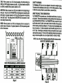
(4) Reference LEDs (2) Modular Jacks
(В) R4-45 7 RJ-11 Selector Switch ® Receiver LEDs
(C) Cable Under Test
IN TRIPLETT
Inplett Corporation One Triplett Drive — Bluffton, OH 45817 -
800-TRIPLETT
FAX: 419-358-7956 www.iriplett.com
(F) Locas / Remote Selector Switch
84-822 Rev A 5/00
WireMaster XR-2 FEATURES:
a} Verifies point to point wiring of twisted pair LAN cables, telephone cables,
and other types of cables that use RJ-11 and RJ-45 connectors.
b) Checks for continuity in cable conductors
¢} Generates two distinct warble tones usable for cable tracing
d) 8 LEDs identify the source and destination of each conductor
e) Direct connection of 6 pin RJ-11 or 8 pin RJ-45 cables
f} Allows remote testing of long cable runs up to 1000 feet
g) TELCO protected
h) Long battery life
SPECIFICATIONS:
Output Tone: Approximately 5 volts peak to peak square wave.
Protection: Will withstand 56 VDC with 400 Ohms series resistance applied
across any of the connector’s pins for 2 minutes. Will withstand
75 VAC peak with 100 Ohms series resistance superimposed
onto 56 VDC for 100 milliseconds.
(TELCO bias and ringing current)
Cable Types: Any cable with RJ-11 connectors on both ends, or RJ-45
connectors on both ends.
Battery: 3 voit alkaline, NEDA 1604A, such as Eveready 522
Battery Life: Approximately 100 hours
Size: (EACH UNIT). 3.7" x 2.4" x 1.1" (93mm x 61mm x 28mm)
Weight: (EACH UNIT): Less than 5 ounces without battery installed
CONFIGURATION OPTIONS:
The WireMaster XR-2 TRANSMITTER unit can be configured by placing shorting
blocks on the two pin headers on the PC board. There are four different options
that will work in any combination of jumper settings (see Figure 1). They are as
follows:
TYPE: When no jumper is on J103, the unit defaults to a 4 conductor RJ-11 test.
The middle four LEDs will sequence 2, 3, 4, 5, 2, 3, ect. If a jumper is placed on
J103, the unit will sequence the middle six LEDs to test a 6 conductor RJ-11 cable.
This option is functional only when the RJ-45/RJ-11 switch is set to RJ-11.
TONE: When no jumper is on J104, the unit generates a Hi pitched warble tone
(800Hz and 700Hz toggling between each other). A LO pitched warble tone (600Hz
and 500Hz) is enabled when a jumper is placed on J104.
DIRECTION: When no jumper is on J105, the unit defaults to the Straight-through
wiring test. The LEDs on the TRANSMITTER unit will sequence in ascending order
(left to right). If a jumper is placed on J105, the LEDs will sequence in descending
order (right to left). This setting allows the RECEIVER LEDs to sequence in order
when testing Reversed wiring.
SPEED: When no jumper is on J106, the unit sequences from one conductor to
another in about 0.6 seconds. If a jumper is placed on J108, the sequencing speed
will be 4 times slower,
À,
[0000000
ti HE Ш 8 AA EN FN ENF" NN 0
Lo LA EE THE BE CEE
USER PROGRAMMABLE JUMPER DIAGRAM
JUMPER FUNCTION NO JUMPER WITH JUMPER
[os | TP | Rrtt4pn | RAT16ph
res | томЕ | нь | 107»
DIRECTION | FORWARD | REVERSE —
лоб | seep | noma | stow
Figure 1 N
SAFETY WARNING:
The WireMaster XR-2 test set is not designed to be used on energized cables.
This test set will not withstand a direct cross to 110 VAC 60Hz power line. Failure
to follow this waming will lead to product failure or personal injury
WIRE TRACING, TONE GENERATION:
The TRANSMITTER can generate one of two distinct warble tones, a low pitch or
a high pitch. These are user selectable by moving shorting blocks inside the unit
(see CONFIGURATION OPTIONS). Two TRANSMITTER units, one set for HI pitch
and the other set for LO pitch, can be used to trace two cables at the same time
without creating confusion (see Figure 2). The tones are sent automatically when
the unit is tumed on. For direct connection, insert the cable's plug into the RJ-45
or AJ-11 jack. Connecting via a wall plate or wiring hub requires the use of a patch
cable (optional accessory). The far end of the cable being traced can be located by
using an inductive amplifier such as the Triplett HOUND or HOUND 2 PROBE.
NOTE: Use on live LAN or Telephone cables will yield erroneous results.
NEVER TEST ENERGIZED CABLES.
WIRE TESTING INSTRUCTIONS /
“LOCAL TEST” FOR JUMPER CABLES
Attach the TRANSMITTER to one end of the cable to be tested, inserting the cable's
connector into the appropriate jack on the TRANSMITTER, and setting the switch on
the TRANSMITTER to agree with the jack being used. Connect the RECEIVER to the
other end of the cable, inserting the connector on the cable into the appropriate jack
on the RECEIVER. If the cable being tested is a “jumper cord”, and both the TRANS-
MITTER and the RECEIVER units are visible to the user, set the switch on the RE-
CEIVER to LOCAL. Observe the LEDs on the TRANSMITTER and the RECEIVER as
they sequence through the test.
On a “straight through” cable, the LEDs on the TRANSMITTER and on the RECEIVER —
will sequence together {regardless of whether the TRANSMITTER is set to FORWARD
or REVERSE direction), lighting the same LEDs on the TRANSMITTER and RECEIVER.
On some cables, some LEDs on the RECEIVER may not light. This may be normal,
depending on the number of conductors in the cable.
For example, tele hone cables, which use 6 pin RJ-11 connectors, often have но 2
or 4 conductors in them. Consequently, only 2 or 4 LEDs will light up on the RE-
CEIVER. Telephone cables are often wired in reverse.... so when LEDs 2,3,4, and 5
light up in sequence on the TRANSMITTER (TRANSMITTER set to FORWARD), LEDs
5,4,3, and 2 will light up in sequence on the RECEIVER.
LAN “crossover” cables conforming to the EIA 568 standard have two pairs of wires
“crossed over” in the cable. Pins 1&2 at one end of the cable are wired to pins 3&6 at
the other end of the cable. The other wires in the cable, although unnecessary in
most LAN systems using the 568 standard, are usually wired straight through. Hence,
on a typical crossover cable with RJ-45 connectors, when the TRANSMITTER is se-
quencing the LEDs from 1 to 8, the LEDs on the RECEIVER should sequence:
E CP ACE "ETA +
fran any of the LEDs that are supposed to light, do not light, then the conductors in the
cable associated with the unlit LEDs are OPEN. If conductors are shorted together,
the LEDs associated with the shorted conductors may glow dimly or not at all. If the
LEDs on the RECEIVER flash in an inappropriate sequence, the conductors in the
cable are mis-wired to one or both of the connectors.
WIRE TESTING INSTRUCTIONS / "REMOTE TEST”
Attach the TRANSMITTER to one end of the cable to be tested, inserting the cable's
connector into the appropriate jack on the TRANSMITTER, and setting the switch on
the TRANSMITTER to agree with the jack being used. Connect the RECEIVER to the
other end of the cable, inserting the connector on the cable into the appropriate ¡ack
on the RECEIVER. Use patch cords as necessary if checking installed cables with
connectors on wallplates. If the TRANSMITTER and RECEIVER cannot be seen si-
muitaneously, set the switch on the RECEIVER to REMOTE.
On a “straight through” cable (with “straight through” patch cords), the TRANSMIT-
TER DIRECTION (J105) must be set to FORWARD. The LEDs on the TRANSMITTER
and on the RECEIVER will sequence together, ligh ting the same LEDs on the TRANS-
MITTER and RECEIVER. At the RECEIVER end, it is only possible to observe that the
LEDs are flashing in sequence from left to right. 99% of the time, this is adequate
indication that the wiring is correct.
On “reverse wired" cables, the TRANSMITTER DIRECTION (J105) must be set to
REVERSE. The LEDs on the TRANSMITTER and on the RECEIVER will sequence
opposite to each other. At the RECEIVER end, it is only possible to observe that the
LEDs are flashing in sequence from left to right. 99% of the time, this is adequate
indication that the wiring is correct.
However (using a “straight through” wired cable as an came since the LEDs on
the TRANSMITTER cannot be seen, it is not possible to tell if a particular LED on the
TRANSMITTER is lit, when the same number LED on the RECEIVER is lit. That is, it is
not possible to tell if the TRANSMITTER is sequencing 1_2_3..... etc, while the RE-
CEIVER is sequencing 1_2_3.... etc. The TRANSMITTER might be sequencing 5_6_7....
etc. while the RECEIVER 15 sequencing 1_2_3... ec. At the RECEIVER end, the se-
quencing of the LEDs would seem to in dicate that the cable is OK, when it is actually
wired wrong. For this reason, the #3 LED (RJ-45 label) on the RE CEIVER performs a
special “stagger test”, If the ВЕСЕМЕР $ сиси! try detects a possible mis-wiring, the
#3 LED will not light, even though the actual wire going to the #3 pin of the connector
may be OK.
This might be because the cable is “reverse wired”. A reverse wired cable should be
obvious to the user, because with the TRANSMITTER set to FORWARD, instead of
REVERSE as it is supposed to be set, the LEDs on the RECEIVER will sequence from
nght to left (instead of left to nght), and the #3 LED on the RECEIVER will not light.
Similarly, attempting to test a “straight through” wired cable with the TRANSMITTER
DIRECTION set to REVERSE will result in the same indications on the RECEIVER.
A simple, although not 100% accurate test for this condition, is to set the switch on
the RECEIVER to LOCAL. If the 43 LED now lights, it is likely the cable is wired
incorrectly for the setting of the DIRECTION jumper.
If this is the case, the TRANSMITTER can be set to the opposite direction to check
this particular cable. This is done by placing a jumper on J105, as described in DI-
RECTION.
if the DIRECTION is changed in the TRANSMITTER, and the #3 LED still does not
iight at the RECEIVER with the switch in REMOTE, the wire connected to the #3 pin
(RJ-45) might be open. To find out, set the switch on the RECEIVER switch to LO-
CAL. If the #3 LED on the RECEIVER now lights, and the LEDs flash in sequence, the
#3 wire is not open, but the cable is mis-wired in a configuration called “stag-
gered”, This is a very unlikely condition, but one which is technically feasible.
it is possible to remotely test cables other than “straight through” or “reverse wired"
types. However, the test may not be 100% accurate, because the user cannot see
which LEDs are lighting on the TRANSMITTER when he is at the RECEIVER end.
in general, if any of the LEDs that are supposed to light, do not light, then the con-
ductors in the cable associated with the unlit LEDs are OPEN. If conductors are shorted
together, the LEDs associated with the shorted conductors may glow dimly or not at
all. If the LEDs on the RECEIVER flash in an inappropriate sequence, the conductors
in the cable are mis-wired to one or both of the connectors.
“NEXT” TEST:
The WireMaster XR-2 does not perform a NEXT (Near End Crosstalk) Test. NEXT
testing venfies that specific conductors in a cable are connected to specific pins on
the RJ connectors. The WireMaster XR-2 verifies that specific pins are connected
together, but it does not verify that specific conductors are used to do this. On short
LAN cables (less than 10 feet) and telephone cables (of any length), this is seldom a
problem. However, on long LAN cables, “crosstalk” created by using the wrong
conductors in the cable, may cause the LAN to malfunction. This means that some
LAN cables may test OK on the WireMaster XR-2, but may not work when placed
into service. The Triplett PairMaster will perform NEXT tests on LAN cables.
BATTERY REPLACEMENT: |
Remove the screw on the back of the TRANSMITTER's case. Remove the case front.
Replace the battery. Reassemble the case. The RECEIVER unit does not require a
battery.
SAMPLE RESULTS:
LED Flashing Order Cable Fault
1 2345678 NONE, Cable OK
21345678 Wire 1 8 Wire 2 reversed В
|] - - 45678 Wire 2 & 3 shorted together or both Open
1 23-5678 Wire 4 Open
4 5312678 Pair 1/2 transposed with Pair 4/5
123756438 Wire 4 & Wire 7 are switched
8 7654-21 (RJ-45) Wired in Reverse, see WIRE TESTING
TRIPLETT ONE YEAR LIMITED WARRANTY
Tha Tipielt Comoration werunts instruments and test mancéactured by À 10 be irse from defective material or workmanship and agrees to repair or
RS EE césciose the defect to be the fault of our with no charge within one year of the date
para ed ral ae error cn gere pp
PROBE HR |
napiacng, or making fund on any instrament or tesi equipment which proves te be within ons year bom the date of original purchasa.
This warranty dass not apply 10 a of our whick have been repaired or alenid by unauthorizad pavsans in any way 50 83, 10 aur 30M judgment,
to
jure their stabllly or reliability, or which have been subject to misuse, abuse, misapplication, sccident or which have had iha serial numbers
añured, delaced, er AT. Accestortés, including batteries and Ases, noi of our mandectura used with this product are nol coverad By this wamanty.
Fo register » chaine veder the provisions of this warranty, refum the instrument or tes! equipmint to Corporation, Service Department, One Drive,
Bhdfion, Ohio 65617, Iraasportation propaid. N AA TPM
ALL WARRANTIES IMPLIED BY LAW ARE HEREBY UMITED TO A PERIOD OF ONE YEAR FROM DATE OF PURCHASE, AND THE PROVISIONS OF THE
WARRANTY ARE EXPRESSLY IN LIEU OF ANY OTHER WARRANTIES EXPRESSED OR IMPUED.
The purchaser to sstume of for me which may resoll from the misuse of the the is
empleos dr abves, vel rapredión presas La Ms tamal TOR DONE AO ASS iodo edita
or consequential damages,
r
Some states {USA ONLY) do not allow the exclusion or imitation of incidental or conseguental sa the above limitation or exclusion may not apply io
you. a TR AE EE AES ipleft Caporalion in connection with the sale of ifs
Fripiatt Comoration reserves the right lo discontinue models at any time, or change specifications, peice of design, withaw! notice and without incuring any
Thés warranty gives you specific legal rights, and you may have eibar rights which vary om state Io state.