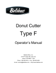
1
ADVANCED BUILDDING TECHNIQUES
YYoou’
u rree now intimattel
ely faami
ely
milil arr wit
ith tthhe innne
ith
nerr wo
w rkinngs
off ppri
r ms and all of th
ri
the bbuuilld opti
oppti
t on
ons.
s Witth a lil tttle
p ac
pr
acti
tice
ti
ce you sho
houl
uldd bbee aabl
blee too con
bl
onst
s rruucctt jus
st
ustt ab
abouut
annyt
anyt
y hi
hin
ing. Buut noow it
it’s
’s tim
imee yo
youu ro
rollll uupp yo
your sleeev
e es
e andd
reealllyy gett dir
irty
ty.. In thi
h s ch
c ap
apte
terr yo
you ar
aree go
goin
ingg ttoo refine
yoour
ur build
l inng te
t ch
chni
niqu
ques
es and ppus
ushh thhe liimi
us
mits
ts ooff whhat
prrimss caan do for
o yoouu.
042-057 Chapter 03.indd 42
9/5/07 1:27:27 AM
CONTENTS
PRIM TORTURE ..........................44
WORKING WITH TINY PRIMS ............50
BUILDING BY THE NUMBERS .............52
TUTORIAL: BUILDING A STAIRCASE ......54
042-057 Chapter 03.indd 43
9/5/07 1:27:31 AM
CHAPTER 3
PRIM TORTURE
PRIM
TORTURE
WORKING
WITH TINY
PRIMS
BUILDING
BY THE
Prim torture is the phrase Second Life builders use to describe the sick, sadistic process of
morphing prims into exotic new shapes that even Linden Lab may not have anticipated. The results
can be useful, bizarre, artistic, and sometimes utterly paradoxical. This section will expand your
understanding of how prims really work and arm you with some tips and tricks to get the most bang
from your prim buck.
NUMBERS
TUTORIAL:
BUILDING A
STAIRCASE
■ PATH CUT
.750
.625
.875
.000
.500
.375
.125
.250
Figure 3.1: Commonly used cut values on a box prim
44
Figure 3.2: Four steps created using four prims (left),
and the same number of steps created using just two
prims (right)
042-057 Chapter 03.indd 44
A path cut causes a wedge gap to
appear in the prim such that the point of
the wedge lines up with the prim’s z-axis.
An easy way to visualize this is to imagine
the prim as a pie viewed from above, and
the path cut as a slice taken away by a
hungry kid. The cut will normally begin
in the corner of the prim for those that
have corners, such as boxes and prisms.
You can choose any value between 0 and
1 but there are eight commonly used
cuts you should commit to memory for
frequent use (Figure 3.1). Cut values
of 0.0, 0.25, 0.5, and 0.75 are used
to create diagonal cuts from corner to
corner while values of 0.125, 0.375,
0.625, and 0.875 create cuts from
edge to edge.
Path cuts are essential for creating
shapes that are more complex and
detailed than the basic building blocks
themselves. For example, to create a
drawer handle you could use a hollow
cylinder or torus and then cut it in half
(cut value 0.5). However, path cuts
can also be used to conserve prims.
Let’s say you’re building a set of stairs,
each step 0.25 meters tall. You might
consider using one box for each step,
but by using cuts you can halve the
number of prims. Simply use a 0.5meter box path cuts of 0.125 and
0.875, creating an L-shaped prim.
Stacking these boxes corner to corner
would give you the exact same steps but
would consume only half the number of
prims (Figure 3.2)!
9/5/07 1:27:32 AM
■ HOLLOW
Remember that the Hollow feature works along
the path of an extruded 2D shape. This means
that for linearly extruded objects a hollow will
appear along the z-axis (much like with path
cuts), but for radially extruded objects Hollow will
hollow out a rounded shape. While most hollow
shapes match the extruded 2D shape, you can
also hollow out a circle, a square, or a triangle.
Figure 3.3: A room using four prims (left), and
the same room using one prim (right)
Like path cuts, Hollow can be used to help
save prims. For example, if you want to create
a room with four walls, you might use one box
per wall, totaling four boxes. But the savvy
builder could use one large hollowed box (Figure
3.3). That’s four wall surfaces for the price of
one! If you need to add a door, simply play with
the cut values. (Unfortunately, the door will have
to appear in the corner of the room since that’s
where box path cuts start.)
WARNING
CHAPTER 1
CHAPTER 2
CHAPTER 3
CHAPTER 4
CHAPTER 5
CHAPTER 6
CHAPTER 7
CHAPTER 8
CHAPTER 9
CHAPTER 10
CHAPTER 11
CHAPTER 12
CHAPTER 13
CHAPTER 14
APPENDICES
INDEX
Using a hollow prim as a room is a great way to save prims, but it has one drawback: When you
try to alt-zoom inside the room, Second Life’s camera will become confused and start behaving
as though you are trying to look at the outside of the prim. This can be annoying, so using a
hollow prim as a room is recommended only when prim conservation is your highest priority.
■ TWIST
Twists are the weapon of choice for many organic builds, such as trees and flowers. Like hollows,
twists occur along the path of extrusion, so they behave quite differently for linearly extruded objects
and radially extruded objects. Linearly extruded objects are fairly straightforward; for example,
twisting a box can give it a cruller shape, and if tapered to a point it could make a convincing drill or
unicorn horn.
Radially extruded objects, on the
other hand, cause one of the ends of the
extruded loop to break continuity and flip
around. If you enter a twist of 180 degrees
on the beginning part of a tube it causes
a half-twist, where it once again meshes
up seamlessly with the end. This creates
the famous shape known as a Möbius strip
(Figure 3.4). Performing the same trick on a
torus makes a pretty, lily-like flower shape.
Figure 3.4: Transforming a tube into a Möbius
strip using twist
042-057 Chapter 03.indd 45
Many prims become distorted when
twisting. Here is a cool trick that takes
advantage of this. As you know, there is
a 10-meter limitation on prim sizes. But
say you wanted a cylinder larger than 10
meters—perhaps for the foundation of a
castle or for a landing pad for a spaceship.
45
9/5/07 1:27:35 AM
CHAPTER 3
Impossible? Not if we torture the
prims enough! Create a 10-meter
tube and set the Y Hole Size (the
hole size on the y-axis) to 0.05,
which is the smallest possible
value. Now enter a begin (B)
twist of 90 and an end (E) twist
of 90. I recommend starting at
smaller Twist values and working
up gradually to 90 so you can see
how the prim becomes distorted
and begins to spread out. By the
time both values are set to 90,
you’re left with a cylinder that has
a 20-meter diameter! It almost
feels like cheating (Figure 3.5).
PRIM
TORTURE
WORKING
WITH TINY
PRIMS
BUILDING
BY THE
NUMBERS
TUTORIAL:
BUILDING A
STAIRCASE
Twists can sometimes
be used in compensating for
lower mesh detail in cylinders.
Figure 3.5: A 10m cylinder (background) and a 20m tube
Remember that all prims, even
twisted to “cheat” the 10m size limit (foreground)
round ones, are actually made up
of flat, triangular polygons. People
with lower-end graphics cards
typically run with lower mesh-detail settings, and so cylinders may appear blocky. Adding just a little
twist—maybe a value of 25 or so—creates a greater illusion of roundness.
Finally, twists behave very strangely on spheres, enabling the most abstract art designs. As you
know, spheres are radially extruded semicircles. Adding twist to a sphere will cause these semicircles
to rotate around the point that would be the circle’s center. This causes some odd effects when
part of the semicircle pulls away from the z--axis and leaves a section of the prim “undefined.” This
undefined area allows you to see right through the sphere!
MORE INFO
USING LEVEL OF DETAIL (LOD) TO YOUR ADVANTAGE
Level of detail (or LOD, as it is usually called) is a graphics trick used for processing
management. Prims, when viewed from a distance, are rendered with fewer polygons. This
has a number of annoying effects, along with a few useful ones.
Among the annoyances is the apparent shrinking of round prims—most notably the
sphere, but also the tube, ring, torus, and cylinder—compared to rectangular prims and to
each other. You can see this by creating two dissimilar prims next to each other, then using
your camera controls to zoom back from them. When producing rounded-corner builds, the
effect is quite apparent.
One of the most useful unintended aspects of LOD is the one-prim door called an
automatic iris (because of the way the opening dilates and contracts like an iris). To produce
this, rez a box and hollow it to 95.0. Now give it an end twist of 90 degrees and a z-axis
height of 0.01. As you zoom your camera toward it, it will appear to open; it will seem to close
as you zoom away. This is because SL is rendering it with fewer polygons as the distance from
the camera increases. However, the effect will not be the same to each viewer—your friend
standing back some distance may see you walk through a seemingly closed door.
46
042-057 Chapter 03.indd 46
9/5/07 1:27:37 AM
■ TAPER
Figure 3.6: Tapering turns the prism into a mysterious shape
with a two-dimensional side.
Taper is fairly straightforward with
linearly extruded prims. It lets
you transform a cylinder into a
cone, and a box into pointy box.
This is handy, especially when you
want to create an obelisk or a
monument. But tapering a prism
is far more interesting. Let’s try
it. Rez a prism and set the begin
(B) and end (E) taper values to
0.00. Now slowly increase the B
taper value to 1.0 and watch the
sides of the shape. You will notice
that one side buckles outward
while another side buckles inward.
In fact, the inward-buckling side
buckles so far that when you
reach a taper of 1.0, part of the
prim becomes two-dimensional
(Figure 3.6). This is because all
prims are made up of triangular
polygons. Press Ctrl+Shift+R to
see the wireframe of the prim
so you can see how the prim
distortion works.
CHAPTER 1
CHAPTER 2
CHAPTER 3
CHAPTER 4
CHAPTER 5
CHAPTER 6
CHAPTER 7
CHAPTER 8
CHAPTER 9
CHAPTER 10
CHAPTER 11
CHAPTER 12
CHAPTER 13
CHAPTER 14
APPENDICES
INDEX
As always, Taper is a different animal when applied to radially extruded objects. For tori, tubes,
and rings, Taper works very much like the Hole Size option, except that the change in 2D base
object size happens only on one end rather than on both.
■ TOP SHEAR
For linearly extruded prims, Top
Shear offsets the 2D base shapes
along the x- and y-axis so they are
no longer located directly on top
of one another. This creates a
slanted or sheared appearance.
The maximum offset is 50 percent,
so there will always be at least a
50 percent overlap between the
top and bottom shapes.
Figure 3.7: Shear on a linearly extruded shape (left) versus a
radially extruded shape (right)
042-057 Chapter 03.indd 47
For radially extruded prims,
Top Shear is more like “side shear.”
The two parallel shapes that are
moved in relation to each other
are located opposite each other
halfway along the circular route
around the z-axis. This makes the
prim slope from one side of the
loop to another (Figure 3.7). This
looks fairly natural and can be
useful for organic builds such as
statues of animals or people.
47
9/5/07 1:27:39 AM
CHAPTER 3
Sheared tubes behave much like
other radially extruded prims, but
you may notice that the tube looks a
little odd when Top Shear is applied to
it. The top and the bottom seem to
have a little distortion in the form of
a bump. But when you look inside the
prim by doing a path cut of B = 0.250
and E = 0.750 you can plainly see that
the distortion is caused by the inside
corners of the base 2D rectangle,
which do not tilt when shear is applied
(Figure 3.8).
PRIM
TORTURE
WORKING
WITH TINY
PRIMS
BUILDING
BY THE
NUMBERS
TUTORIAL:
BUILDING A
STAIRCASE
Figure 3.8: Shear applied to a tube looks odd. A crosssection of the prim shows that the rectangular base
shapes are the reason.
■ HOLE SIZE
Hole Size exists only on radially extruded prims. As mentioned in Chapter 2, “Mastering Second Life’s
Basic Building Blocks,” this feature has a very confusing name since its values control the hole size
only indirectly by adjusting the dimensions of the 2D base shape. The X value (which represents the
x-axis) adjusts the hole depth, while the Y value (which pertains to the y-axis) makes the hole smaller
by widening the base shape.
Hole Size is useful for fine-tuning tori destined to become vehicle tires or inner tubes. You can
also use it to simulate the cylinder’s hollow effect on a tube.
■ PROFILE CUT
Profile Cut is available only in radially
extruded prims. This feature is
extremely useful for creating a variety
of complex shapes that look like they
use many more prims than they
actually do!
48
Figure 3.9: Aimee’s five-prim patio-furniture set. The
stools are minor variations on the table design.
042-057 Chapter 03.indd 48
Let’s explore the Profile Cut
options by making a little lounge table
out of a tube. Set Hollow to 95 and
Hole Size Y = 0.45. Now do a profile
cut of B = 0.25 and E = 0.90. As
you can see, we now have a lovely
restaurant table complete with base,
a central stand, and a tabletop, all
with one single prim! If you want to
simulate a tablecloth, set the profile
cut B = 0.20. By copying and reducing
the size of the table, the same design
can make for attractive low-prim chairs
(Figure 3.9).
9/5/07 1:27:40 AM
The torus is even more interesting
with Profile Cut. Doing a profile cut of
E = 0.65 will give you a shape with a
round base. I like to stretch this shape
along the z-axis and use it as a low-prim
streetlamp. Now set Hollow to 95 and
set Profile Cut to E = 0.55. You’ll start
to see an hourglass shape (Figure 3.10),
which you can adjust using the Hole Size
Y value.
Figure 3.10: This torus has some sexy curves!
■ RADIUS DELTA AND REVOLUTIONS
CHAPTER 1
CHAPTER 2
CHAPTER 3
CHAPTER 4
CHAPTER 5
CHAPTER 6
CHAPTER 7
CHAPTER 8
CHAPTER 9
CHAPTER 10
CHAPTER 11
CHAPTER 12
CHAPTER 13
CHAPTER 14
APPENDICES
INDEX
Radius Delta is available only for radially
extruded prims. It lets you vary the
distance for the 2D base shapes from
the prim’s z-axis. The result looks
something like a scroll (Figure 3.11).
To see this, rez a tube, set the Hole
Size Y value to 0.05, and set the
Radius Delta to 0.947.
This scroll is rolled up for only one
revolution. If you want to roll the scroll
up more, you will need to change the
Revolutions setting; however, there are
some catches. First, you’re allowed a
maximum of 4.00 revolutions. Second,
the moment you change the revolutions,
the Skew value for the prim is adjusted
automatically to prevent any part of the
prim from overlapping with itself. This
Figure 3.11: A scroll created by adjusting the Radius
creates a prim that looks more like a
Delta of a tube
spring or a telephone cord than a scroll.
To see the effect of Revolutions on Skew, rez a tube and change the Revolutions value from 1.00 to
1.01. You will notice that the prim instantly sets its Skew to 0.50.
TIP
Although some edit features are available only for certain prims, you can sometimes carry those
effects over to other kinds of prims. For example, if you apply a dimple to a sphere then change
the prim type to box, you will be left with a box that is smaller than the size values indicate. (See
the section “Building a Tiny Box” for details.) Feel free to experiment with different settings, and
then switch prim type to get results that go beyond even Linden Lab’s expectations.
49
042-057 Chapter 03.indd 49
9/5/07 1:27:42 AM
CHAPTER 3
PRIM
TORTURE
WORKING
WITH TINY
PRIMS
BUILDING
BY THE
NUMBERS
TUTORIAL:
BUILDING A
STAIRCASE
Figure 3.12: Aimee making cute banana curls using revolved,
tapered tori. Plywood-colored hair is in fashion this season!
Using Revolutions
values on a torus is the
foundation of an entire
Second Life industry known
affectionately as Hoochie
Hair. To make a single
curl of hair, rez a torus,
set Revolutions to 4.00,
set the X and Y taper to
1.00, and set the skew to
about 0.90. You now have
a curly strand of hair. Copy
this approximately eight
thousand times, link, and
apply to the head (Figure
3.12). You now have a ‘doo
that will slow anybody’s
client to a grinding
halt (which obviously is
undesirable, so use tori
spraringly!). We will talk
more about hair creation in
Chapter 5, “Working with
Clothing and Accessories.”
WORKING WITH TINY PRIMS
As you recall, the minimum size for any prim is 0.010 meters, or one centimeter. This is fine for
most builds, but some projects (such as jewelry) require far more intricate detail. This section will
extend your knowledge of prim torture to whittle the little prims down to almost microscopic sizes.
■ BUILDING A TINY BOX
We will start by making a box that is 0.005 meters on all sides. To do this, we will “trick” the box into
being smaller than advertised by adding a dimple.
1. Rez a box.
2. Change the box to a sphere under Object
▶ Building Block Type.
3. Set the Dimple Begin value to 0.50 (leave the End value as 1.00).
4. Change the prim type back to a box.
5. Set Path Cut B = 0.625 and E = 0.875.
6. Use Shift+Alt to size the prim as small as it can get.
50
042-057 Chapter 03.indd 50
9/5/07 1:27:45 AM
Technically this prim is
still 1 centimeter in size, but
by using Path Cut and Dimple
we got the actual size to half
a centimeter for any given
side. Figure 3.13 should
give you a feel for how much
smaller things can get from
the 0.01m minimum.
Figure 3.13: Three boxes of size 0.5m, 0.010m, and 0.005m
CHAPTER 1
CHAPTER 2
CHAPTER 3
CHAPTER 4
CHAPTER 5
CHAPTER 6
CHAPTER 7
CHAPTER 8
CHAPTER 9
CHAPTER 10
CHAPTER 11
CHAPTER 12
CHAPTER 13
CHAPTER 14
APPENDICES
INDEX
■ BUILDING AN EVEN TINIER BOX
Hollow, when combined with cuts and dimples, can also be used to overcome the 0.010-meter
minimum prim size limit. Let’s try it.
1. Rez a sphere.
2. Set Hollow to 95 and set Dimple to B = 0.53 and E = 0.55.
3. Set the Path Cut to B = 0.620 and E = 0.640.
4. Shrink the whole prim using the size handles until it’s a teeny-weenie prim.
The prim is now a
fraction of the size of the
1-centimeter box (Figure
3.14)! To make slight
adjustments on the shape of
the prim to get something
closer to a cube, you may
want to reduce the hollow or
the dimple.
Figure 3.14: Even compared to the 0.005m prim (the third one
from the left), the micro prim is barely a speck!
042-057 Chapter 03.indd 51
51
9/5/07 1:27:46 AM
CHAPTER 3
■ CONSTRUCTING A DELICATE CHAIN
Let’s create the links of a very delicate
chain (Figure 3.15).
1. Rez a torus and size it down to
0.010 on all sides.
PRIM
TORTURE
2. Set Hollow to 95 and set Profile
Cut values to B = 0.28 and E =
0.30. We now have a very tiny
chain link that is about half a
centimeter in diameter, but let’s
not stop there.
WORKING
WITH TINY
PRIMS
BUILDING
BY THE
NUMBERS
TUTORIAL:
BUILDING A
STAIRCASE
3. Set the hole size to value X =
0.25 and Y = 0.45. You could go
even smaller, but the shape would
no longer look like a chain link.
Figure 3.15: Aimee examines her miniscule new bling
bling made with hollow-cut tori.
4. Now copy and rotate the teeny
prims until you have a little chain.
5. Turn on Shiny for a pretty,
metallic look.
TIP
You just learned how to make a tiny item, but after you have those skills, you can simplify
things by working on a large scale when working with small prims, then resizing the item when
it’s complete. In most cases (especially for rings), I will work at 50× scale so that no dimension
(x-, y-, or z-axis size) will be less than 0.5m. I use cuts and tapers to produce sizes smaller
than my chosen minimum. When you must work with small prims, work on top of a larger
prim with a contrasting color. It is very easy to lose tiny pieces.
When determining final size of your item (at least when it’s intended to be sold or shared),
consider that other people may want it a different size than how you made it. Allow for a little
extra shrinking.
BUILDING BY THE NUMBERS
By now you must think you’re quite the hotshot, using movement, size, and rotation handles like
a pro. But don’t get too smug—your work is going to be sloppy until you learn one more critical
concept: building by the numbers.
52
The limitations of the prim handles become apparent when a project has little room for error.
When adjacent prims are not positioned perfectly against each other, you may see a subtle line
042-057 Chapter 03.indd 52
9/5/07 1:27:48 AM
disrupting the smooth surface. When prims overlap improperly, the textures on the overlapping prims
may “flicker” as they fight to decide which texture is on top. When you build by the numbers you use
some simple math to position and size your prims perfectly.
CHAPTER 1
CHAPTER 2
CHAPTER 3
■ THE M WORD (MATH)
For our first example, we’ll build a 20-meter-long wall. As you know, the prim size limit is 10 meters,
so we will have to use two prims.
1. Rez two prims and enter the following size values: X = 10.000, Y = 0.500, and Z = 5.000.
2. Copy and paste the Y and Z position values of the first wall over to the second wall.
This will line up the two wall segments on all but one axis.
We don’t want the same values for the X position on both wall segments; that would cause both
wall segments to occupy the same exact space! Instead we will do a little math so both prims are
precisely side by side.
3. Find the length of the first prim (the x-axis size) and divide it by two. (That’s 10 ÷ 2 = 5.)
4. Find the length of the second prim (the x-axis size) and divide it by two.
(That’s also 10 ÷ 2 = 5.)
CHAPTER 4
CHAPTER 5
CHAPTER 6
CHAPTER 7
CHAPTER 8
CHAPTER 9
CHAPTER 10
CHAPTER 11
CHAPTER 12
CHAPTER 13
CHAPTER 14
APPENDICES
INDEX
5. Add the two together. (5 + 5 = 10.) You now have the offset.
6. Find the x-axis position for the first prim, add the offset of 10 to that value, and paste the
result into the X position for the second prim.
If you did everything correctly you should have two wall segments sitting side by side. There will
be no gaps and no overlap. It’s mathematically perfect!
■ USING SNAP TO GRID
Another way to build precisely is to use
the grid and the Snap to Grid option.
The Use Grid option is found in the Edit
window along with an Options button
that allows you to control the details.
To use the grid, grab the planar drag
handles (the little triangular move
handles) for the axis along which you
wish to move. A white grid will appear
around your prim; the grid includes a
solid white line that represents grid
units, and finer lines that represent
sub-units. You can toggle Snap to Grid
mode by pressing G or going to Tools
▶ Snap to Grid. Snapping to the grid
is a lifesaver when it comes to allowing
you to set precise positions without
having to do as much math.
Figure 3.16: The Grid Options window
042-057 Chapter 03.indd 53
By setting the Ruler mode in the
Edit window, you can chose between
using the global grid, which is based
on global coordinates, and local grid,
which adjusts the grid to fit the prim’s
current position. You can also elect to
53
9/5/07 1:27:51 AM
CHAPTER 3
PRIM
TORTURE
WORKING
WITH TINY
PRIMS
BUILDING
snap one or more prims to the grid along the x- and y-axis using Tools ▶ Snap Object XY to Grid, or
by pressing Shift+X. This can be handy because it works on multiple selected prims, saving you the
trouble of having to snap each one individually to the grid.
For finer grid control, you can bring up the Grid Options window (Figure 3.16) by pressing the
Options button in the Edit window, going to Tools ▶ Grid Options, or pressing Ctrl+Shift+B. This
window allows you to set the grid units and the extents for the grid, and brings up a slider that lets
you set the opacity for the grid. You can also get a finer level of detail by changing the grid units or
enabling the Sub-Unit Snapping option. The Show Cross Sections option colors the area of the prim
where it intersects the grid, making it easier to judge perspective.
Finally, you can change the characteristics of the grid itself by using the Use Selection for Grid
option in the Tools menu or by pressing Shift+G. This feature will adjust the proportions for the grid
units based on the dimensions and rotation of the currently selected prim.
BY THE
NUMBERS
TUTORIAL:
BUILDING A
STAIRCASE
TUTORIAL: BUILDING A STAIRCASE
One of the biggest pains in
the virtual keister is making
stairs. The problem is that
very small errors from one
step to the next eventually
result in a sloppy overall
appearance. Therefore,
“eye-balling” stairs is not
recommended (but give
it a shot so you can see
for yourself!). Instead, you
should use the Grid Options
menu to make perfect
stairs in record time
(Figure 3.17).
Figure 3.17: Stairs made perfect by using grid features
1. Make the first
step. Rez a box
and set its size
to X = 1.500, Y
= 0.400, and Z =
0.050. That’s a
fine-looking step.
2. Now bring up the Grid Options window and set Grid Units to 0.300 meters. This is a
decent distance from one step to the next.
3. Now you must make sure the first step is aligned to the grid, so pull on the planar drag
handles in all directions until the prim snaps into one of the grid spots.
4. Now Shift-drag the planar drag handles upward, creating a whole new step, and then drag
the step in the Y direction.
54
042-057 Chapter 03.indd 54
5. Now do it again, 10 more times. Ta-da! Perfect steps.
9/5/07 1:27:51 AM
■ BUILDING A SPIRAL STAIRCASE
Now let’s make something a
little more impressive—a spiral
staircase (Figure 3.18). This time
we’re going to use a combination of
grid-snapping and rotation.
1. Rez a step with the same
dimensions as the last
step (X = 1.500, Y =
0.400, and Z = 0.050)
and again, set Grid Units
to 0.300.
Figure 3.18: Perfect spiral stairs
2. We now want to link a
pivot point into the step.
Drag-copy another step
in the X direction so both
steps sit side by side, then
resize this new prim so
that it’s a perfect square
(set X = 0.400).
CHAPTER 1
CHAPTER 2
CHAPTER 3
CHAPTER 4
CHAPTER 5
CHAPTER 6
CHAPTER 7
CHAPTER 8
CHAPTER 9
CHAPTER 10
CHAPTER 11
CHAPTER 12
CHAPTER 13
CHAPTER 14
APPENDICES
INDEX
Now we want to place the two prims perfectly side by side, so we are going to use the math we
learned earlier.
3. Take half the X size of the first prim (1.5 ÷ 2 = 0.75) and half the X size of the second
prim (0.4 ÷ 2 = 0.200).
4. Add the two together (0.75 + 0.2 = 0.95).
5. Find the X position of the first prim, add 0.95 to it, and then use that as the X position
value for the smaller pivot prim.
You now have two prims set perfectly side by side. You may want to tint the smaller pivot prim
to another color, such as red—you will be deleting the other pivot prims later, but for now we will be
using them as a center point for rotation.
Now you need to link the two prims together. In the previous chapter I mentioned how the order
in which you select prims prior to linking is very important. Well this will be your first real example as
to why. When we link prims, the last prim selected becomes the root prim—the prim around which
the whole build will rotate when we start to enter rotational values.
6. Select the long step first, and then Shift-select the smaller pivot prim. Press Ctrl+L
to link your prims. (The root prim glows yellow when selected, while all other prims
glow blue.)
7. As we did with the regular staircase, we want to start out with our stair snapped to a
spot on the grid. Go to Tools ▶ Snap Object XY to Grid (or use Shift+X), and then use the
planar drag handles to snap the step on the z-axis.
8. Using the planar drag handles, Shift-drag the step upward to produce another step.
9. Do this several more times until you have a stack of steps with 0.300 meters between
every step.
Now we are going to rotate each step by entering incrementally larger numbers into the Z rotation
axis. We can rotate each step at any increment as long as we use the same increment for each step. I
think 10 degrees of rotation per step will look nice.
042-057 Chapter 03.indd 55
55
9/5/07 1:27:53 AM
CHAPTER 3
10. Leave the first step alone (z-axis rotation of zero) and set the Z rotation for the second
step to 10.00 degrees. (The next one will be 20.00 degrees, then 30.00, then 40.00, so
on and so on.)
You should now see an attractive spiral staircase. The next step will be to remove the
pivot points.
PRIM
TORTURE
WORKING
WITH TINY
PRIMS
11. Select all the steps and press Shift+Ctrl+L to unlink them all.
12. Delete all but the first little pivot steps; the rest are no longer needed.
TIP
BUILDING
BY THE
NUMBERS
TUTORIAL:
BUILDING A
STAIRCASE
Why keep the first pivot point? Well, when you get used to building by the numbers, certain
prims may become valuable simply because they hold position or size data that you may need
later. In this case, we’re going to place a cylinder down the center of the spiral staircase. You
could rez a new cylinder and then go through the mathematical process of finding the exact
center of the spiral, but why bother? The pivot prim contains that information already!
Now we’ll build a column that will finish off the look of our spiral staircase.
13. Edit the first little pivot step.
14. Set the building-block type to Cylinder.
15. Stretch the cylinder along the z-axis until it becomes a mighty support pole, giving
apparent strength to our beautiful creation.
56
042-057 Chapter 03.indd 56
9/5/07 1:27:54 AM