1
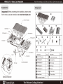
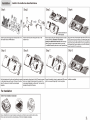
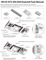
HR-03 GTX 285/260 Heatsink Pack Manual
Apply the additional aluminum heatsinks to where as depicted in the illustrations.
(When applying the VRM heatsinks, other than the contact with the chips they're designed for, make sure the heatsinks are not
touching other chips to prevent a possible short-circuit)
Heatsink-2 x 1 Heatsink-3 x 1 Heatsink-4 x 5
NEW additional aluminum heatsinks
7 Heatsink-1
NN Q
Heatsink-2
HSI Heatsink
HSI Push Pin
RAM Heatsink-C -
Original aluminum heatsink pack GTX260 (55nm) GTX260 (55nm)
that came with the HR-03 GTX
Inset of VRM part
NEW additional aluminum heatsinks
© ==
ANDE QL
= С
dre О
EEE О
HSI Heatsink- НЫ ©
orn
Е О
HSI Push Pin - € ©
RAM Heatsink-B- a
GTX285
Inset of VRM part
GTX285
Original aluminum heatsink pack
that came with the HR-03 GTX
HR-03 GTX Video Card Heatsink Note: When installing on a GTX280 or GTX260, a 120mm fan must be used.
Exploded View Component
Important! Before proceeding with installation, please check
for the most up-to-date instructions at www.thermalright.com
HR-03 GTX Heatsink
Bracket Mount
Screw
RAM Heatsink A
HSI Heatsink
® © ©
<> <=
Parts Name Piesce(s) Parts Name Piesce(s)
Thermal Pad O HR-03 GTX Heatsink 1 O 120mm Fan Wire Clip 2
#) RAM Heatsink A 6 |) HSI Push Pin 8
Cross-shaped backplate © RAM Heatsink B 2 D M2 nut cap 4
@ RAM Heatsink C 2 |®@ m2 Screw 4
© RAM Heatsink D 1 ® Washer 4
@ Hs! Heatsink 1 |@ Thermal Pad 1
OY Bracket Mount 1 15) Thermal Paste 1
Backside Illustration O Cross-shaped backplate 1
mm Thermalright The Ultimate Cooling Solutions!
Installation
Install in the method as described below
Step1:
Step2:
7) Backside illustration of
Y RAM heatsinks
Insert the push pins through each mounting hole on the
HSI heatsink and the PWN heatsink.
Insert the four M2 screws through the holes on the
bracket mount.
Remove stock cooling then thoroughly clean the surface
of every RAM chip. Important: if not cleaned
properly, the adhesives will not stick! After thorough
cleaning, apply the appropriate heatsink to the chips.
For detailed illustration please refer to the Exploded View.
Apply an even layer of thermal paste to the surface of GPU and to
the HSI chips as well as to the bottom of the heatsink base. Apply
the bracket mount from Step 2 by placing it on top of the heatsink
base and then place the GPU heatsink in such way as depicted in
the Exploded View. Place the heatsink on top of GPU with the M2
screws through the GPU mounting holes.
Step 7:
Step 8:
Hold the heatsink and the video card together by pressing
on the heatsink base and the card. Flip over to the other
side of the video card to install the cross-shaped
backplate.
Insert washers through each of the M2 screws to prevent
short circuit. Apply the thermal pad to the center of the
cross-shaped backplate (on either side). Then Insert the
backplate through the M2 screws.
Secure the heatsink in place by capping each M2 screws
with the nut caps till finger tight. Do not over tighten.
Installation completed.
Fan Installation
120mm-fan-installation illustration
Place a 120x25mm fan on top of heatsink. Insert each end of the fan wire clip into the fan clip hole.
Pull on wire clip to hook into fan mounting holes. 120mm fan Installation completes.