Transcript
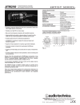
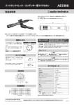
ATM650
HYPERCARDIOID DYNAMIC
INSTRUMENT MICROPHONE
ATM650 SPECIFICATIONS†
• Tailored response for musical instrument pickup–guitar cabinets,
snare and other percussion
• Hypercardioid polar pattern reduces pickup of sounds from the
sides and rear, improving isolation of desired sound source
ELEMENT
Dynamic
POLAR PATTERN
Hypercardioid
FREQUENCY RESPONSE
80-17,000 Hz
OPEN CIRCUIT SENSITIVITY
–56 dB (1.5 mV) re 1V at 1 Pa*
IMPEDANCE
300 ohms
WEIGHT
279 g (9.8 oz)
DIMENSIONS
164.2 mm (6.46") long,
38.8 mm (1.53") diameter
OUTPUT CONNECTOR
Integral 3-pin XLRM-type
ACCESSORIES FURNISHED
AT8470 Quiet-Flex™ stand clamp
for 5/8"-27 threaded stands;
5
/8"-27 to 3/8"-16 threaded adapter;
soft protective pouch
†In the interest of standards development, A.T.U.S. offers full details on its test
methods to other industry professionals on request.
*1 Pascal = 10 dynes/cm2 = 10 microbars = 94 dB SPL
Specifications are subject to change without notice.
• Durable performance for professional applications
Frequency Response
Polar Pattern
Response in dB
• Special dual-wall floating construction reduces handling noise and
assures consistent performance from mic to mic
• Hi-ENERGY® neodymium magnet for improved output and
transient response
• Multi-stage flat grille design is engineered to enable easy
placement as close as possible to sound source
Frequency in Hertz
LEGEND
12" or more on axis
SCALE IS 5 DECIBELS PER DIVISION
LEGEND
• Corrosion-resistant contacts from gold-plated XLRM-type
connector
200 Hz
1 kHz
5 kHz
8 kHz
• Rugged, all-metal design and construction for years of trouble-free
use
Output from the microphone's XLRM-type connector is low
impedance (Lo-Z) balanced. The signal appears across Pins 2 and
3; Pin 1 is ground (shield). Output phase is “Pin 2 hot” – positive
acoustic pressure produces positive voltage at Pin 2.
To avoid phase cancellation and poor sound, all mic cables must be
wired consistently: Pin 1-to-Pin 1, etc. For a high-impedance (Hi-Z)
mic input, connect a Lo-Z balanced cable to a Hi-Z matching
transformer (A-T CP8201 or equal) at the equipment input.
When using the ATM650 in settings with a stage monitor speaker,
the speaker should be located 135° off axis (45° off the rear of the
microphone). This placement, in conjunction with the microphone's
uniform hypercardioid pickup pattern, will virtually eliminate the
possibility of undesired audio feedback.
Take care to keep foreign particles from entering the windscreen. An
accumulation of iron or steel filings on the diaphragm, and/or foreign
material in the windscreen's mesh surface, can degrade
performance.
Note: Remove the rubber sleeve at the base of the microphone
handle to use the AT8471 isolation stand clamp (not included) for
more secure, permanent installation.
Audio-Technica U.S., Inc., 1221 Commerce Drive, Stow, Ohio 44224
Audio-Technica Limited, Old Lane, Leeds LS11 8AG England
www.audio-technica.com
P51805
©2006 Audio-Technica U.S., Inc.
Printed in China