Download Sennheiser SK 5212
Transcript
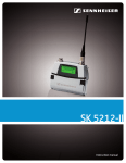
SK 5212
Instructions for use
Contents
Safety instructions .... ............ ............ ............ ........... ............ ............ ............ ......... 3
Delivery includes ....... ............ ............ ............ ........... ............ ............ ............ ......... 3
The SK 521 2 bodypack transmitter .......... ........... ............ ............ ............ ......... 4
The operating controls ......... ............ ............ ........... ............ ............ ............ ......... 5
Indications and displays ...... ............ ............ ........... ............ ............ ............ ......... 6
The LC display panel ...... ............ ............ ........... ............ ............ ............ ......... 6
Preparing the transmitter for use .. ............ ........... ............ ............ ............ ......... 8
Inserting and changing the battery ... ........... ............ ............ ............ ......... 8
Connecting the microphone ..... ............ ........... ............ ............ ............ ......... 9
Connecting the antenna ............ ............ ........... ............ ............ ............ ......... 9
Attaching the transmitter to clothing .......... ............ ............ ............ ....... 10
Using the transmitter ........... ............ ............ ........... ............ ............ ............ ....... 10
Switching the transmitter on/off ....... ........... ............ ............ ............ ....... 10
Doing a frequency check ........... ............ ........... ............ ............ ............ ....... 11
The operating menu . ............ ............ ............ ........... ............ ............ ............ ....... 12
The buttons ......... ............ ............ ............ ........... ............ ............ ............ ....... 12
The automatic lock mode (autolock function) ........ ............ ............ ....... 13
Working with the operating menu ..... ........... ............ ............ ............ ....... 15
Overview of the operating menu ........ ........... ............ ............ ............ ....... 19
Adjustment tips for the operating menu . ........... ............ ............ ............ ....... 21
Selecting a channel – CHAN ...... ............ ........... ............ ............ ............ ....... 21
Selecting the frequencies to be stored in the channel bank “VAR”
– TUNE ....... ........... ............ ............ ............ ........... ............ ............ ............ ....... 21
Entering a name – NAME .......... ............ ........... ............ ............ ............ ....... 23
Adjusting the microphone sensitivity – ATTEN ....... ............ ............ ....... 24
Adjusting the bass roll-off frequency – LOWCUT ... ............ ............ ....... 24
Selecting the standard display – VIEW ......... ............ ............ ............ ....... 24
Loading the factory pre-set default settings – RESET ....... ............ ....... 25
Activating/deactivating the automatic lock mode – LOCK ........... ....... 25
Adjusting the output power – POW ER .......... ............ ............ ............ ....... 26
Exiting the operating menu – EXIT ..... ........... ............ ............ ............ ....... 26
Maintenance and care .......... ............ ............ ........... ............ ............ ............ ....... 26
If problems occur... .... ............ ............ ............ ........... ............ ............ ............ ....... 27
Error checklist ...... ............ ............ ............ ........... ............ ............ ............ ....... 27
Information on the compander system .... ........... ............ ............ ............ ....... 28
1
Accessories ............ ........... ............ ............ ............ ........... ............ ............ ............ .
Specifications ....... ........... ............ ............ ............ ........... ............ ............ ............ .
Pin assignment of microphone socket .... ........... ............ ............ ............ .
Audio sensitivity ...... ............ ............ ............ ........... ............ ............ ............ .
Manufacturer declarations ....... ............ ............ ........... ............ ............ ............ .
Warranty regulations .......... ............ ............ ........... ............ ............ ............ .
CE Declaration of Conformity ......... ............ ........... ............ ............ ............ .
Batteries ......... ........... ............ ............ ............ ........... ............ ............ ............ .
WEEE Declaration ..... ............ ............ ............ ........... ............ ............ ............ .
28
29
30
30
31
31
31
31
31
Thank you for choosing Sennheiser!
We have designed this product to give you reliable operation over many
years. Over half a century of accumulated expertise in the design and
manufacture of high-quality electro-acoustic equipment have made Sennheiser a world-leading company in this field.
Please tak e a few moments t o read the se instructio ns care fully , as we want yo u
t o enjo y yo ur new Sennheiser products quickly a nd to the fulle st.
2
Safety instructions
! Please read these instructions carefully and completely before using the
unit.
! Make these instructions easily accessible to all users at all times. Always
include these instructions when passing the unit on to third parties.
! Never open electronic units! If units are opened by customers in breach of
this instruction, the warranty becomes null and void.
! Water entering the housing of the unit can cause a short-circuit and
damage the electronics. Protect the unit from damp and wet. Only use a
slightly damp cloth to clean the unit.
Intended use of the unit
Intended use includes
! having read these instructions especially the chapter “Safety
instructions”.
! using the unit within the operating conditions as described in these
instructions.
Improper use of the un it
Improper use is when you use the unit other than described in these
instructions or when you use the unit under operating conditions different
from those described in these instructions.
Delivery includes
!
!
!
!
!
1 SK 5212 bodypack transmitter
1 battery
1 antenna
1 belt clip
1 instructions for use
3
The SK 5212 bodypack transmitter
The SK 5212 is a professional Mikroport bodypack transmitter that is easy
to use and is easily adaptable to a wide variety of applications.
The SK 5212 bodypack transmitter has the following features:
! Extremely compact diecast metal housing
! Very rugged casing
! Special protection against the ingress of moisture
! Backlit LC display
! Menu-assisted operation
! Specially suitable for multi-channel applications
! 36 MHz switching bandwidth
! Transmission frequencies tunable in steps of 5 kHz
! 50 mW output power, adjustable to 10 mW
! Constant output power until the battery is completely discharged
! Audio sensitivity adjustable in steps of 1dB, sensitivity range of 70 dB
! HiDyn plusTM noise reduction system
! Signal-to-noise ratio > 110 dB(A)
! Switchable low-cut filter
! Battery status display, battery status also transmitted to the receiver
! Reliable, easy-to-use clip attachment
The channel bank system
The transmitter has two channel banks. The channels of the channel bank
“FIX“ (fixed bank) have been factory pre-set to customer-specific
transmission frequencies. These frequencies cannot be changed.
The channel bank “VAR” (variable bank) allows you to freely select and
store frequencies.
Suitab le receivers
! EM 10 46 system
! EM 35 32, EM 3031, EM 3032
! EK 30 41
4
The operating controls
Microphone input
Red LED for operation and
battery status indication
(ON/LOW BAT/PEAK)
Antenna socket
LC display, backlit
Battery compartment
Battery compartment cover
Battery compartment catches
Type plate
Multi-function switch with three
switch positions:
(DOWN), (UP) and SET
ON/OFF button
5
Indications and displays
The LC display panel
RF
AF
CH dB MHz
Alphanumeric display
Level display for audio signal “AF”
“RF” – appears when an RF signal is transmitted
Lock mode icon (lock mode is activated)
“Hz” – appears when the low-cut frequency is displayed
“MHz” – appears when the transmission frequency is displayed
“dB” – appears when the microphone sensitivity is displayed
“CH” – appears when the channel number is displayed
Battery status display
Display backlighting
When the lock mode is deactivated, the display remains backlit for approx.
20 seconds after pressing a button.
6
The LED display
The red LED provides information on the operating state of the
transmitter.
Red LED lights up normally: The transmitter is switched on and the
capacitiy of the battery is sufficient (ON).
Red LED is flashing:
The battery is going flat
(LOW BATT)!
Red LED lights up brightly: The transmitter is fully modulated (PEAK).
7
Preparing the transmitter for use
Inserting and changing the battery
For powering the transmitter, use a 1.5 V AA size alkaline-manganese
battery.
Open the battery compartment by
pushing the two catches in the
direction of the arrows and open the
cover .
Insert the battery as shown in the
diagram on the left. Please observe
correct polarity when inserting the
battery.
Close the battery compartment.
8
Connecting the microphone
The transmitter is designed for use with Sennheiser lavalier microphones
and headmics (-4 versions). The power supply of these microphones is via
the microphone input of the transmitter.
Connect the microphone to the microphone
input of the transmitter.
Screw down the coupling ring.
Connecting the antenna
The transmitter is supplied with a plug-on antenna.
Connect the antenna to the antenna socket of the transmitter.
Screw down the coupling ring.
9
Attaching the transmitter to clothing
The transmitter is attached to clothing (e.g.
belt, waistband) with the supplied belt clip.
The clip is detachable so that you can also
attach the transmitter with the antenna
pointing downwards. To do so, withdraw the
clip from its fixing points and attach it the
other way round.
Using the transmitter
Switching the transmitter on/off
Open the battery compartment.
To switch the transmitter on, briefly
press the ON/OFF button .
The red LED lights up normally and
the standard display is shown on the LC
display panel ; after a short pause,
“RF” appears on the LC display panel.
Note:
! Remove the battery when the transmitter will not be used for extended periods of time.
10
! The transmitter can only be switched off when the lock mode is
deactivated (see “The automatic lock mode (autolock function)” on
page 13).
To switch the transmitter off, press the
ON/OFF button until “OFF” appears on
the LC display panel .
The red LED and the LC display panel go
off.
Note:
! When in the setting mode of the operating menu, the ON/OFF button
will cancel your entry (ESC function).
Doing a frequency check
The transmitter has a frequency check mode that prevents the transmitter
transmitting on an unwanted frequency after switch-on.
W hen switching on the transmitter, keep
the ON/OFF button pressed.
The current frequency is displayed on the
LC display panel without the transmitter actually transmitting.
If the displayed frequency is the correct
RF
one, release the ON/OFF button .
After five seconds, “RF” appears on
the LC display panel and the transmitter
is transmitting.
MHz
To change the transmission frequency, proceed as follows:
Release the ON/OFF button .
Immediately (i.e. within five seconds) press the multi-function
switch (switch position SET) twice.
You are now in the setting mode of the “CHAN” or “TUNE” menu where
you can change the transmission frequency (see “Adjustment tips for
the operating menu” on page 21).
11
The operating menu
The buttons
Button
Mode
Function
ON/OFF
button
Switched off
! Briefly pressing the button:
Switches the transmitter on
! Keeping the button pressed:
Does a frequency check
Display mode
! Briefly pressing the button
(with activated autolock function):
Immediately activates the lock mode
! Briefly pressing the button
(with activated lock mode):
Calls up the lock mode for deactivation
! Pressing the button for 3 sec.
(with deactivated lock mode):
Switches the transmitter off
SET
Selection mode
Cancels the entry and returns to the display mode
Setting mode
Cancels the entry and returns with the
last setting stored to the last parameter
displayed in the display mode
Display mode
! With deactivated lock mode:
Changes to the selection mode
! With activated lock mode:
Calls up the lock mode for deactivation
12
Selection mode
Changes to the setting mode of the
selected menu
Setting mode
Stores the setting and returns to the
selection mode (“STOR ED” is displayed)
Button
Mode
(UP)/
Display mode
(DOWN)
Function
Changes to the previous parameter ()
or changes to the next parameter ()
Selection mode
Changes to the previous menu () or
changes to the next menu ()
Setting mode
Increases () or reduces () the setting
of the selected menu
The automatic lock mode (autolock function)
The transmitter has an automatic lock mode (autolock function) that can
be activated via the “LOCK” menu (see “Activating/deactivating the automatic lock mode – LOCK” on page 25). When the autolock function is activated, the lock mode is automatically activated 10 seconds after pressing
the last button.
RF Prior to this, the lock mode icon flashes
several times on the LC display panel ,
indicating that the lock mode is being
MHz
activated and, at the same time, the display
backlighting goes off.
Note:
The autolock function can be deactivated permanently (see page 25) or
temporarily (see page 14).
13
Deactivating th e autolock function temporarily
To make changes to the settings via the operating menu, you can
temporarily deactivate the lock mode.
Press the ON/OFF button or the multifunction switch (switch position
SET). “LOCK” appears on the LC display
panel .
Slide the multi-function switch to the
position (UP) or (DOWN).
“UNLOCK” appears on the LC display
panel .
Press the multi-function switch (switch positionSET). You can now
change the settings.
SET
DOWN
UP
After you have exited the operating menu, the lock mode is automatically
activated after 10 seconds. You can activate the lock mode immediately by
briefly pressing the ON/OFF button .
14
Working with the operating menu
The operating menu has three modes:
! Display mode
In display mode, you can display the current menu settings one after the
other – even when the lock mode is activated.
! Selection mode
In selection mode, you can select the menu whose setting you want to
change. To change to the selection mode, the lock mode must be deactivated.
! Setting mode
In setting mode, you can change the setting of the selected menu.
By way of example of the “LOWCUT” menu, this section describes how to
use the operating menu.
Selection Mode
Display Mode
Setting Mode
SET/ON
MHz
MHz
SET
SET
TUNE
SET
LOWCUT
MHz
SET
Current low-cut
frequency
120
Hz
MHz
Adjusting
the low-cut
frequency
Current low-cut
frequency
STORED
FLAT
Hz
SET
FLAT,
120 Hz
15
After switch-on
After switch-on, the standard display is shown on the LC display panel .
Depending on the setting, the transmission frequency, the channel number
or the name of the transmitter is displayed.
Displaying the menu settings in display mode
In display mode, and with the lock mode activated, you can display the
current menu settings one after the other (see “Overview of the operating
menu” on page 19). After a few seconds, the display returns to the
standard display.
Slide the multi-function switch to the
SET
UP
DOWN
position (UP) or (DOWN) to display the
menu settings. If you slide the multi-function
switch repeatedly to the same position, all
menu settings are displayed one after the
other.
Changing to the selection mode
To change from display mode to selection mode, you have to deactivate the
lock mode.
Deactivate the lock mode as described in the chapter “Deactivating the
autolock function temporarily” on page 14. You can now select the
menu whose settings you want to adjust.
Press the multi-function switch (switch position SET) to change to
the menu that was displayed in display mode.
Selecting a menu
Slide the multi-function switch to the position
SET
DOWN
UP
(UP) or (DOWN).
Press the multi-function switch (switch
position SET).
The name of the selected menu starts flashing.
16
The following menus are available:
Menu
Function of the menu
CHAN
Selecting a channe l
TUNE
Setting transmissio n frequencies for t he channel bank
“VA R” (va riable bank)
NAME
Ent ering a name
ATTEN
Adjusting the micro phone sensi tivity
LOWCUT
Adjusting the ba ss roll-o ff frequency
VIEW
Selecting the sta ndard display
RESET
Lo ading the fa cto ry pre-set default settings
POWER
Adjusting the output power
LOCK
Act ivat ing/de act ivating the autolo ck function
EXIT
Exiting t he o perating menu and returni ng to t he sta ndard
display
Changing to the setting mode of a selected menu
Press the multi-function switch (switch
SET
DOWN
UP
position SET) to change to the setting mode
of the selected menu.
The current setting that can be adjusted
flashes on the LC display panel .
Adjusting a settin g
Use the multi-function switch to adjust the setting of the selected menu.
By briefly sliding the multi-function switch to the position (UP) or (DOWN), the display jumps either forwards or backwards to the next setting.
In the “ATTEN”, “CHAN”, “TUNE” and “NAME” menu and when slid to the
position (UP) or (DOWN), the multi-function switch features a “fast
search” function, i.e. the display cycles continuously. In the “TUNE” menu,
the cycling of the display is continuously accelerated. The “fast search”
function allows you to get fast and easily to your desired setting.
17
Storing a setting
Press the multi-function switch (switch
SET
DOWN
UP
position SET) to permanently store a setting.
“STORED” appears on the display panel,
indicating that the setting has been stored.
The display then returns to the top menu level.
With most menus, new settings become effective immediately without
having to be stored. An exception are the “TUNE” and “CHAN” menus. With
these menus, new settings only become effective after they have been
stored (“STORED” appears on the LC display panel , indicating that the
setting has been stored).
Exiting the operating menu
Select the “EXIT” menu to exit the operating
menu and to return to the standard display.
When in the operating menu, pressing the ON/
OFF button will cancel your entry (ESC
function) and return you to the standard
display with the last stored settings.
18
Overview of the operating menu
Deactivate the lock mode before adjusting the settings (see “Deactivating
the autolock function temporarily” on page 14). Pressing the ON/
OFF button will cancel your entry (ESC function) and return you to the
display mode.
Display mode
Setting mode
Selection mode
530.050
1 sec.
MHz
CH MHz
Transmission
frequency
1 sec.
SET CHAN
RF SET
FIX. 01
VAR. 20
CH
CH
CH
Current
channel bank
Changing the
channel bank and
the channel
/ : Channel
VAR.01...20
FIX.01...20
/ : Channel
FIX.01...20
VAR.01...20
SET
STORED
VAR. 20
Keep SET pressed
SET TUNE
RF
MHz
Current frequency
CH
Current channel
SET
Setting the
frequencies for
the channels of
channel bank
"VAR"
VAR. 20
VAR. 01
CH
CH
Current channel
/
:
VAR.01...20
SET
1 Sek.
530.050
530.050
MHz
MHz
Current frequency
Current frequency
516.205
516.205
MHz
/
MHz
: Sets the
/
frequency
frequency
SET
STORED
RF SET
Current name
NAME
Assigning a
name
RF SET
VOCAL
RF
LOCAL
/
Current name
STORED
: Sets the
SET
RF
: Name
(6 characters)
Letters w/o
pronounciation
marks, numbers
from 0...9, special
characters, spaces
19
Display mode
RF
AF
IIIIIIII
Setting mode
Selection mode
SET
ATTEN RF SET
RF
12
Adjusting the
attenuation
Current
modulation
RF
13
dB
dB
/ : Adjust the
attenuation in
1-dB steps
Current
attenuation
setting
SET
STORED
SET
dB
Current
attenuation
SET
LOWCUT
RF SET
120
Hz
Current low-cut
frequency
Adjusting the
low-cut frequency
RF
Hz
Current low-cut
frequency setting
RF SET
FREQ
RF
Hz
FLAT,
120 Hz
SET
STORED
VIEW
FLAT
RF
RF
NAME
CH
Selecting the
standard display
Current standard
display
SET
STORED
RESET
RF SET
Loading the
factory-preset
default settings
LOCK
RF SET
Setting the
autolock function
RST. NO
/ : FREQ,
CHAN, NAME
RST. OK
RF
Security check
SET
LOC. ON
RF
Adjusting the
output power
/ :
EXIT
VAR. 01
PWR.LO
PWR.HI
SET
RF
RF
Exiting the
operating menu
dB
SET
MHz
20
LOC.ON
LOC.OFF
PWR.HI
Current setting
STORED
"reset" = NO
reset is cancelled
SET
SET POWER RF SET PWR.LO
Current output
power
/ : OK, NO
"reset" = OK
LOC. OFF RF
Current setting
STORED
RF
Adjustment tips for the operating menu
Selecting a channel – CHAN
Via the “CHAN” menu, you can switch between the channels in the channel
banks “FIX“ and “VAR“. The transmitter is not transmitting while this
adjustment is being made.
When changing to the setting mode of the “CHAN” menu, the current
channel number appears on the diplay. After approx. 1 second, the
currently assigned transmission frequency is displayed.
1 sec.
CH
CH
CH
MHz
To select a different channel, slide the multi-function switch to the
position (UP) or (DOWN). The new channel number appears on the
display panel for approx. 1 second and then the currently assigned
transmission frequency is displayed.
Only after the new setting has been stored (“STOR ED” has appeared on
the LC display panel) does the transmitter operate on the transmission
frequency of the new channel.
Note:
The frequencies in the channel bank “FIX” can only be changed by a
Sennheiser Service Partner. If you require a special frequency set in this
bank, please contact your local Sennheiser Service Partner.
Selecting the frequencies to be stored in the channel
bank “VAR” – TUNE
Via the “TUNE” menu, you can freely select the frequencies to be stored in
the channel bank “VAR” (variable bank). The transmitter is not transmitting while this adjustment is being made.
Note:
When you have selected the channel bank “FIX” and then select the
“TUNE” menu, the transmitter automatically switches to channel 01 of
the channel bank “VAR” and “VAR” briefly appears on the LC display
panel .
21
The frequencies are tunable in 5-kHz steps within a switching bandwidth of
36 MHz max.
Note:
When operating a multi-channel system, make sure to only use intermodulation-free frequencies.
There are two options for setting the frequencies:
! You can set a new frequency for the selected channel:
In the selection mode of the “TUNE” menu,
SET
UP
DOWN
press the multi-function switch (switch
position SET). The current channel number
appears on the display and then the currently
assigned frequency is displayed.
CH
CH
Change the frequency by sliding the multi-
function switch to the position (UP) or
(DOWN).
MHz
Store your setting.
MHz
! You can change to a different channel and set a new frequency for the
new channel:
Press the multi-function switch (switch
SET
UP
DOWN
RF
22
Select a new channel by sliding the multi-
function switch to the position (UP) or
(DOWN).
CH
CH
CH
CH
position SET) for a longer time. The current
channel flashes on the display.
Confirm your selection by pressing the multifunction switch (switch position SET).
RF
The current frequency of the selected channel
is displayed.
Change the frequency by sliding the multifunction switch to the position (UP) or
(DOWN).
Store your setting.
MHz
MHz
Entering a name – NAME
Via the “NAME” menu, you can enter a freely selectable name for the
transmitter. This name can be displayed on the standard display and can
consist of up to six characters such as:
! letters (without pronounciation marks),
! numbers from 0 to 9,
! special characters and spaces.
After you have changed to the setting mode of the “NAME” menu, the first
segment starts flashing on the LC display panel .
Slide the multi-function switch to the posi-
SET
DOWN
UP
tion (UP) or (DOWN) to select a character.
(By sliding the switch only once, the display
jumps either forwards or backwards to the next
character. If you keep the switch slid, the display starts cycling continuously.)
Press the multi-function switch (switch
position SET) to change to the next segment.
Have you entered the name completely? Press
the multi-function switch (switch position
SET) to store your setting. “STORED” appears
on the LC display panel .
23
Adjusting the microphone sensitivity – ATTEN
Via the “ATTEN” menu, you can adjust the transmitter’s sensitivity.
RF
AF
dB
The sensitivity is correctly adjusted when the level
display for audio signal “AF” shows full
deflection only during the loudest passages or
when the redLED lights up brightly.
The sensitivity can be adjusted in 1-dB steps from
+ 40 dB to –30 dB.
Note:
! The bargraph has a resolution of approx. 3 dB
per segment with a display range of 45 dB.
Adjusting the bass roll-off frequency – LOWCUT
To reduce unwanted low-frequency noise such as wind and handling noise,
you can activate a low-cut filter. The low-cut frequency is 1 20 Hz.
If you do not want to reduce low-frequency signal portions, select the setting “FLAT”.
Selecting the standard display – VIEW
Via the “VIEW ” menu, you can select one of the following standard displays:
RF
RF
CH
CH
MHz
Transmission
frequency “FREQ”
RF
Channel
“CHAN”
Name
“NAM E”
The selected standard display is shown
! after switch-on,
! after the menu settings have been displayed for 10 seconds in display
mode.
24
Loading the factory pre-set default settings – RESET
Via the “RESET” menu, you can load the factory pre-set default settings.
After the reset, the standard display is shown on the LC display panel.
Low-cut frequency
flat
Microphone sensitivity
0 dB
Name
SK5212
Standard display
frequency
Autolock function
deactivated
Channel
FIX 01
Output power
high
Frequencies in the channel bank “VAR” are reset.
Activating/deactivating the automatic lock mode –
LOCK
The transmitter has an autolock function (automatic lock mode) that can
be activated or deactivated via the “LOCK” menu. When the autolock
function is activated, the lock mode is automatically activated 10 seconds
after pressing the last button. The lock mode protects the transmitter from
accidental programming.
In the selection mode of the “LOCK” menu, press
SET
DOWN
UP
RF
RF
the multi-function switch (switch position
SET).
The current setting of the autolock function is
displayed.
Change the setting by sliding the multi-
function switch to the position (UP) or
(DOWN).
Select “LOC.ON” to activate the autolock function or select “LOC.OFF” to deactivate the autolock function.
Store your setting by pressing the multifunction switch (switch position SET).
25
Adjusting the output power – POWER
Licensing regulations may require a limitation of the output power to
10 mW. The transmitter therefore features a switchable output power.
With reduced output power, the operating time increases.
Exiting the operating menu – EXIT
Via the “EXIT” menu, you can exit the operating menu and return to the
standard display.
When in the operating menu, briefly pressing the ON/OFF button will
cancel your entry (ESC function) and return you to the standard display
without saving any changes.
Maintenance and care
CAUTION!
26
Water can damage the electronics of the unit!
Water entering the housing of the unit can cause a shortcircuit and damage the electronics.
Only use a slightly damp cloth to clean the unit. Do not
use any cleansing agents or solvents.
If problems occur...
Error checklist
Pr oblem
Possible cause
Possible solution
No operatio n
indicatio n
Bat tery is flat or inserted
i ncorrectly
Re pla ce the bat tery o r
check if it is insert ed
co rrectl y
Transmitter
ca nnot be
sw itched off/
Sett ings canno t be
changed
Lo ck mode is activat ed
Deactiva te the lo ck mo de
(see “Dea ctiv ating the
autolo ck functi on
temporarily ” on page 14)
Recei ver:
No RF signa l
T ransmit ter and rece iver
a re not o n t he same
channel
Set t ra nsmitt er and re cei ver to the sa me cha nnel
T ransmit ter is out of ra nge
Che ck t he sque lch
thre shold setting on the
rece iver o r reduce the
dista nce betwee n receiving
antenna and t ransmitt er
T ransmit ter’s se nsitiv ity is
set too high
See “A djusting t he micro phone sensit ivity – A TTEN ”
on pa ge 24
Receiv er’s o utput lev el is
set too low
Increase the line o ut put
level
T ransmit ter’s se nsitiv ity is
set too low
See “A djusting t he micro phone sensit ivity – A TTEN ”
on pa ge 24
Receiv er’s o utput lev el is
set too high
Re duce the l ine o ut put leve l
Audi o signal has a
high level o f
ba ck gro und no ise
Audi o signal is
di sto rted
If problems occur that are not listed in the above table or if the problems
cannot be solved with the proposed solutions, please contact your local
Sennheiser agent for assistance.
27
Tips for optimum reception
! Transmission range depends to a large extent on location and on the
selected output power. There should be a “free line of sight” between
transmitting and receiving antennas.
! To avoid overmodulating the receiver, observe a minimum distance of
5 m between transmitting and receiving antennas.
Tips for multi-channel operation
! When operating a multi-channel system, make sure to only use
intermodulation-free frequencies.
Information on the compander system
This unit is equipped with HiDyn plus™, the Sennheiser noise reduction
system that reduces RF interference. H iDy n plus™ o ffers e xtre me opera tio na l
re liabilit y a nd e nsures highest tra nsmi ssio n qua lity.
Accessories
MKE 2 Gold
MKE 2 Platinum
ME 102
ME 104
ME 105
HSP 2
HSP 4
28
Lavalier microphone, omni-directional
Lavalier microphone, omni-directional
Modular mini-microphone system, omni-directional
Modular mini-microphone system, cardioid
Modular mini-microphone system, super-cardioid
Headmic, omni-directional
Headmic, cardioid
Specifications
Modulation
Frequency range
Switching bandwidth
Transmission frequencies
RF output po wer
Frequency stability
Spurious emissio n
Nominal/peak deviation
Signa l-to-noise ratio
THD
AF frequency response
Noise reduction system
Input sensitivity at
nominal deviatio n, 1 kHz
Lo w-cut frequency (–3 dB)
Power supply
Power consumption
(without LC display illumination)
Operating time
Temperature range
Connections
Dimensions [mm]
Weight
Type approval
wideband FM
450 – 960 M Hz
36 MHz
channel bank “FIX”
with customer-specific frequencies;
channel bank “VAR”
with 20 freely selectable frequencies
(frequencies tunable in steps of 5 kHz)
switchable, typ.: 50 mW (PW R.HI)
10 mW (PW R.LO)
±10 ppm
< 4 nW
±40 kHz/±56 kHz
110 dB(A) r ms
< 0.3 % at nominal deviation, 1 kHz
60–20,000 Hz
Sennheiser HiDyn plus™
–40 dBu = 7.75 mV, adjustable in steps
of 1 dB, range: 70 dB
adjustable (flat, 120 Hz)
1 AA size battery (1.5 V)
appro x. 160 mA at 1.2 V ( PWR.LO)
appro x. 250 mA at 1.2 V ( PWR.HI)
appro x. 11 hrs (PWR.LO)
appro x. 5.5 hrs ( PWR.HI)
–10 °C to +55 °C
AF: 3-pin special microphone socket
RF: coax socket
appro x. 53 x 60 x 17
appro x. 120 g incl. battery
USA:
FCC-Part 74.861
FCC ID: DM OS K5212
Canada: RSS-123, IC: 2099A-SK5212
EU:
requirements of R&TTE
EN 50392
ETSI EN 300 422-1/-2, class II
ETSI EN 301 489-1/-9
CE 0682!
29
Pin assignment of microphone socket
3
1
2
A F so cke t
Pin 1: +5.2 V fo r exte rna l special micropho nes
Pin 2: AF and 5.2 V A B-po wering; 8.2 kΩ int ernal resist ance,
optimized fo r Sennheiser pre-polarize d
co ndenser micro pho nes
Pin 3 a nd thread: gro und
Audio sensitivity
The transmitter’s audio sensitivity can be adjusted over a range of 70 dB
(+4 0 dB to –30 dB) in steps of 1 dB. The diagram below shows the
sensitivity range of the SK 5212 in comparison to the earlier product
generations SK 50 and SK 5012.
SK 50
SK 5012
42
SK 5212
40
36
30
24
18
24
16
12
6
0...42 dB
8
1
8
16
–16...+24 dB
30
–30...+40 dB
Switch position
30
Manufacturer declarations
Warranty regulations
The guarantee period for this Sennheiser product is 24 months from the date of purchase.
Excluded are accessory items and disposable batteries that are delivered with the product; due to their characteristics these products have a shorter service life that is principally dependent on the individual frequency of use.
The guarantee period starts from the date of original purchase. For this reason, we recommend that the sales receipt be retained as proof of purchase. Without this proof (which
is checked by the responsible Sennheiser service partner) you will not be reimbursed for
any repairs that are carried out.
Depending on our choice, guarantee service comprises, free of charge, the removal of
material and manufacturing defects through repair or replacement of either individual
parts or the entire device. Inappropriate usage (e.g. operating faults, mechanical damages, incorrect operating voltage), wear and tear, force majeure and defects which were
known at the time of purchase are excluded from guarantee claims. The guarantee is void
if the product is manipulated by non-authorised persons or repair stations.
In the case of a claim under the terms of this guarantee, send the device, including accessories and sales receipt, to the responsible service partner. To minimise the risk of transport damage, we recommend that the original packaging is used. Your legal rights against
the seller, resulting from the contract of sale, are not affected by this guarantee.
The guarantee can be claimed in all countries outside the U.S. provided that no national
law limits our terms of guarantee.
CE Declaration
of Conformity
This equipment is in compliance with the essential requirements and other relevant provisions of Directives 1999/5/EC, 89/336/EC or 73/23/EC. The declaration is available on
the internet site at www.sennheiser.com.
Before putting the device into operation, please observe the respective country-specific
regulations!
Batteries
The supplied battery can be recycled. Please dispose of it as special waste or
return it to your specialist dealer. In order to protect the environment, only dispose of exhausted batteries.
WEEE Declaration
Your Sennheiser product was developed and manufactured with highquality
materials and components which can be recycled and/or reused. This symbol
indicates that electrical and electronic equipment must be disposed of separately from normal waste at the end of its operational lifetime.
Please dispose of this product by bringing it to your local collection point or
recycling centre for such equipment. This will help to protect the environment in which
we all live.
31
Sennheiser electronic GmbH & Co. KG
30900 Wedemark, Germany
Phone +49 (5130) 600 0
Fax +49 (5130) 600 300
www.sennheiser.com
Printed in Germany
Publ. 02/06
513626/A01


