1
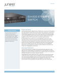
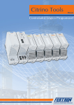
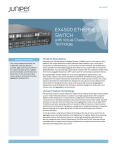
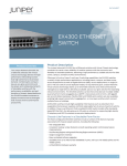
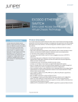
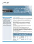
DATASHEET
EX8208 ETHERNET
SWITCH
Product Overview
The EX8208 modular Ethernet switch,
a member of the Juniper Networks
EX Series Ethernet Switches product
family, offers a flexible, powerful,
and modular platform that delivers
the performance, scalability, and
high availability required for today’s
high-density data center, campus
aggregation, and core switching
environments. With a total capacity
of up to 6.2 Tbps, the EX8208 system
provides a complete, end-to-end
Product Description
The eight-slot Juniper Networks® EX8208 Ethernet Switch, part of the Juniper Networks
EX8200 line of Ethernet Switches, is ideal for aggregating access switches such as Juniper
Networks EX3200 and EX4200 lines of Ethernet switches deployed in campus wiring
closets and in data center top-of-rack applications. The EX8208 is also designed to
support 1-Gigabit and 10-Gigabit Ethernet server access in data center end-of-row chassis
deployments. In core applications, the EX8208 provides approximately 960 Mpps of highdensity, wire-speed 10-Gigabit Ethernet performance for the largest campus and data
center networks.
Customers can advance the economics of their network by leveraging the consistent
performance of the Juniper Networks EX8200 line of Ethernet switches’ wire-speed line
cards, in conjunction with the EX4500, EX4200, EX3200 and EX2200 lines of Ethernet
switches and Juniper Networks Junos® operating system to reduce capital and operational
expenses across the network infrastructure.
solution for the high-performance
EX8208 Ethernet Switch
networks of today and into the future.
The EX8208 switch includes an advanced set of hardware features enabled by Juniperdesigned EX-PFE2 ASICs and the carrier-class Juniper Networks operating system, Junos
OS, delivering the capabilities needed to support the high-performance networks of today
and tomorrow.
The EX8208 switch features eight dedicated line-card slots that can accommodate a
variety of EX8200 Ethernet line cards. Options include the following:
• EX8200-48T: a 48-port 10/100/1000BASE-T RJ-45 unshielded twisted pair (UTP)
line card
• EX8200-48F: a 48-port 100BASE-FX/1000BASE-X SFP fiber line card
• EX8200-8XS: an eight-port 10GBASE-X SFP+ fiber line card
• EX8200-40XS: a 40-port 10GBASE-X SFP+ / 1000BASE-X SFP line card
Fully configured, a single EX8208 chassis can support up to 384 Gigabit Ethernet or 64
10-Gigabit Ethernet ports at wire speed, or 320 10-Gigabit Ethernet ports in shared bandwidth
applications, delivering one of the industry’s highest 10-Gigabit Ethernet port densities.
1
At 14 rack-units (RUs) high, three EX8208 Ethernet Switches can
fit in a standard 42 RU rack, enabling up to 1,152 Gigabit Ethernet
or 960 10-Gigabit Ethernet ports in a single rack. At just 21 inches
deep, the EX8208 is sufficiently compact to fit into typical wiring
FEATURES
DESCRIPTION
High
availability
Hardware designed for continuous operation:
• Secure, modular architecture isolates faults
closets, making it ideal for campus deployments where space is at
• Separate control and forwarding planes enhance
scalability and resiliency
a premium.
• Transparent failover and network recovery
• Graceful Route Engine Switchover (GRES)
The EX8208 features a switch fabric that is capable of delivering 320
• Nonstop Routing (NSR)*
Gbps (full duplex) per slot, enabling scalable wire-rate performance
on all ports for any packet size. The passive backplane design
supports a future capacity of up to 6.2 Tbps, providing a built-in
migration path to next-generation deployments.
• Non-Stop Software Upgrade (NSSU)*
Layer 2
features
• Jumbo frames (9216 Bytes)
• 4,096 VLANs
• VLAN Registration Protocol (GVRP)
The base-configuration EX8208 Ethernet Switch includes a
• 802.3ad – Link Aggregation Control Protocol (LACP)
side-mounted hot-swappable fan tray with variable-speed fans,
• 802.1D – Spanning Tree Protocol (STP)
one Switch Fabric and Routing Engine (SRE) module, and one
• 802.1w – Rapid Spanning Tree Protocol (RSTP)
• 802.1s – Multiple Instance Spanning Tree Protocol
(MSTP)
dedicated Switch Fabric module. Base EX8208 switches also
ship with either two 2000 watt or two 3000 watt power supplies,
• VLAN Spanning Tree Protocol (VSTP)
although six power supply bays allow users to provision the
chassis to provide the power and redundancy required for any
application. Redundant EX8208 configurations include a second
• Redundant Trunk Group (RTG)
Layer 3
features
SRE module for hot-standby resiliency while AC or DC power
• Static routing
• RIP v1/v2
• OSPF v1/v2
options provide complete redundancy, reliability, and availability.
• Filter-based forwarding
All components are accessible from the front, simplifying repairs
• Virtual Router Redundancy Protocol (VRRP)
and upgrades.
• BGP (Advanced Feature license)
• IS-IS (Advanced Feature license)
A front-panel chassis-level LCD panel displays Routing Engine
• IPv6 (Advanced Feature license)
status as well as chassis component alarm information for
• Bidirectional Forwarding Detection (BFD)
rapid problem identification and resolution to simplify overall
operations. The LCD also provides a flexible, user-friendly interface
for performing device initialization and configuration rollbacks,
reporting system status and alarm notification, or restoring the
switch to its default settings.
• Virtual routers
Hardware
tunneling
• GRE tunnels (Advanced feature license*)
Multicast
• Internet Group Management Protocol (IGMP)
v1/v2/v3
• IGMP snooping v1/v2/v3
Table 1: EX8208 Features at a Glance
FEATURES
DESCRIPTION
Chassis
• 14 RU; 21 in (53 cm) deep; 17.25 in (43.8 cm) wide
• Protocol Independent Multicast PIM-SM, PIM-SSM,
PIM-DM, MSDP
Firewall filters
– Port ACLs
• 6.2 Tbps backplane capacity
– VLAN ACLs
• Dedicated data, control, and management planes
– Router ACLs
• Energy efficiency: Up to 195,000 packets per second
per watt
• Control plane denial of service (DoS) protection
Quality of
service (QoS)
Routing
engine
Operating
system
• Weighted Random Early Drop (WRED) scheduling
• Shaped Deficit Weighted Round Robin (SDWRR)
queuing
• Strict priority queuing
• Redundant variable-speed fans and controllers
• Multi-field classification (L2 – L4) for scheduling and
rewrite
• 320 Gbps (full duplex) per slot fabric capacity
Management
• Junos OS command-line interface (CLI)
• 2+1 redundancy with dual SREs and SF card
• JUNOScript
• Full line-rate forwarding with two fabrics in system
• Embedded Web-based management – J-Web
• 1+1 redundancy
• Network and Security Manager (NSM) support
• LCD panel
• Master and backup SREs
• 2 gigabytes DRAM; 2 gigabytes Flash memory
• SNMP v1/v2/v3
• Console + auxiliary serial and Ethernet management
ports
• RADIUS
• TACACS+
• USB storage interface
• Extensive MIB support
• Local and remote analyzer (mirroring)
• Junos OS
• Link Layer Discovery Protocol (LLDP)
• Advanced Insight Solutions (AIS)
* Roadmap
2
• 8 egress queues per port
• 10,000 W maximum power capacity
• Side-to-side airflow
Fabric
• 2,000 policers per chassis
• 6 load-sharing power supplies
• 220 V AC, 110 V AC and -48 V DC options for N+1 or
N+N redundancy
Cooling
• Ingress and egress L2-L4 access control lists (ACLs): • 8 dedicated I/O slots
• LCD panel for system monitoring
Power
• MPLS capabilities (Advanced feature license*)
M Series
M Series
EX8208
EX4200
EX4200
EX8208
EX4200
EX4200
EX4200
EX4200
Figure 1: The EX8208 Ethernet Switch offers a high-density, scalable solution for aggregating 10-Gigabit Ethernet
uplinks from access-layer devices in the data center.
Deployment Scenarios
With its high Gigabit Ethernet and 10-Gigabit Ethernet port
The EX8208 switch is optimized for both data center and campus
densities, the EX8208 can also serve as an end-of-row server
aggregation and core deployments.
access switch. High-density Gigabit Ethernet and 10-Gigabit
In the data center, the EX8208 switch delivers a highperformance, high-density platform that reduces cost and
complexity while improving overall scalability and providing
carrier-class reliability. Populated with eight-port EX8200-8XS
Ethernet ports on the EX8208 enable the consolidation
of aggregation and core layers, simplifying the data center
architecture while reducing power, space, and cooling
requirements, and lowering total cost of ownership (TCO).
10-Gigabit Ethernet line cards, the EX8208 can accommodate
The EX8208 switch has a similar impact on campus aggregation
large numbers of high-speed, line-rate uplinks at any packet size
and core environments, where high port densities and carrier-
from access layer devices such as EX4200 switches deployed
class performance enable the switch to support more users with
in Virtual Chassis top-of-rack configurations, offering a scalable
less equipment than traditional solutions. For example, EX4200
solution for supporting more servers with fewer switches. Using
switches deployed in Virtual Chassis configurations provide
the 40-port EX8200-40XS 10-Gigabit Ethernet line card, the
network access for every floor or building throughout a campus
EX8208 can support a similar number of servers using traditional
with 10- Gigabit Ethernet uplinks; the high-density EX8208 can
standalone top-of-rack or blade-server switches.
aggregate Virtual Chassis uplinks within a single platform to
provide high-performance, line-rate connectivity to core switches
or WAN edge routers.
3
Virtual Chassis
Access
Configurations
EX4200
EX4200
EX4200
EX8208
EX4200
EX4200
EX8208
Figure 2: The EX8208 can aggregate Virtual Chassis configurations within a single platform to provide high-performance,
line-rate connectivity to upstream devices.
Virtual Chassis Technology
EX8200 Virtual Chassis configurations are highly resilient, with no
The EX8208 supports Juniper Networks’ unique Virtual Chassis
single point of failure, ensuring that no single element—whether a
technology, which enables two interconnected EX8200 chassis—
chassis, a line card, a Routing Engine, or an interconnection—can
any combination of EX8208s or EX8216s—to operate as a single,
render the entire fabric inoperable following a failure. Virtual
logical device with a single IP address. Deployed as a collapsed
Chassis technology also makes server virtualization at scale
aggregation or core layer solution, an EX8200 Virtual Chassis
feasible by providing simple L2 connectivity over a very large pool
configuration creates a network fabric for interconnecting access
of compute resources located anywhere within a data center.
switches, routers, and service-layer devices such as firewalls and
Virtual Chassis technology can also be used to extend EX8200-
load balancers using standards-based Ethernet LAGs.
based VLANs between data centers by placing an equal number of
In a Virtual Chassis configuration, EX8200 switches can be
switches in both data centers, or by interconnecting two separate
interconnected using either single line-rate 10GbE links or a LAG
Virtual Chassis configurations using a simple L2 trunk.
with up to 12 10GbE line-rate links. Since the Virtual Chassis intraconnections use small form SFP+ interfaces, Virtual Chassis
member switches can be separated by distances of up to 40 km.
If the EX8200 Virtual Chassis switch members are located in the
same or adjacent racks, low cost direct attach cables (DACs) can
be used as the interconnect mechanism.
Since the network fabric created by an EX8200 Virtual Chassis
configuration prevents loops, it eliminates the need for protocols
such as Spanning Tree. The fabric also simplifies the network
by eliminating the need for Virtual Router Redundancy Protocol
(VRRP), increasing the scalability of the network design. In
addition, since the Virtual Chassis Control Protocol (VCCP) used
to form the EX8200 Virtual Chassis configuration does not affect
the function of the control plane, Junos OS control plane protocols
such as 802.3ad, OSPF, Internet Group Management Protocol
(IGMP), Physical Interface Module (PIM), BGP and others running
on an EX8200 Virtual Chassis system behave in exactly the same
way as when running on a standalone chassis.
4
XRE200 External Routing Engine
In an EX8200 Virtual Chassis configuration, the Routing Engine
functionality is externalized to a purpose-built, server-class
appliance, the XRE200, which supports control plane processing
requirements for large-scale systems and provides an extra layer
of availability and redundancy.
All control protocols such as OSPF, IGMP, Link Aggregation Control
Protocol (LACP), 802.3ah and VCCP, as well as all management
plane functions, run or reside on the XRE200. Junos OS high
availability (HA) features can be enabled on the two XRE200s
required in a redundant EX8200 Virtual Chassis configuration. In
the event of an active XRE200 failure, the standby XRE200 takes
over and Junos OS HA features ensure that the state of the Virtual
Chassis, L2/L3 protocols, and forwarding information are not lost.
See the XRE200 data sheet for more information.
Architecture and Key Components
The Routing Engine on the SRE module is based on the field-
The EX8200 line of Ethernet switches feature a number of distinct
proven hardware architecture used by Juniper Networks routers,
architectural elements. The Routing Engine on the SRE module runs
bringing the same carrier-class performance and reliability to
Junos OS, which processes all Layer 2 and Layer 3 protocols and
the EX8208 that Juniper’s routers provide to the world’s largest
manages individual chassis components, while the Switch Fabric
service provider networks. The Routing Engine’s central CPU
module provides the central crossbar matrix through which all data
performs all system control functions and maintains the hardware
traffic passes. The SRE and Switch Fabric modules work together to
forwarding table and routing protocol states for the EX8208
fulfill all Routing Engine and Switch Fabric functions.
switch. Dedicated hardware on the SRE module supports chassis
The EX8200 line cards include ASIC-based packet forwarding
engines—the EX-PFE2— that process network traffic at wire
rate, as well as a line-card processor that provides scalable local
control and status processing. The EX8208 chassis backplane
management functions such as environmental monitoring, while
communication between SRE modules and individual EX8200 line
cards takes place over a dedicated internal Gigabit Ethernet outof-band control interface.
distributes the data, control, and management plane signals
EX8208 Switch Fabric
over independent paths to the various system components and
The switch fabric for the EX8208 switch, which serves as the
distributes power throughout the system. The fan tray provides
central non-blocking matrix through which all network data
cooling to the line cards and control modules with redundant
passes, is distributed across three elements: the dual-redundant
variable-speed fans, while the power supplies convert building
SRE modules and the dedicated Switch Fabric module. Working
power to the internal voltage required by the system.
together, the SRE and Switch Fabric modules deliver the
All EX8208 components are hot-swappable, and all central
necessary switching capacity for the EX8208 switch; when the
functions are available in redundant configurations, providing high
second SRE module is present, the additional switch fabric serves
operational availability by allowing continuous system operation
in hot-standby mode, providing full 2+1 switch fabric redundancy.
during maintenance or repairs.
The Switch Fabric modules are hot-swappable and field-
Switch Fabric and Routing Engine (SRE) Module
The EX8208 SRE module performs two functions: it incorporates
switch fabric, control plane, and management plane functionality
on a single module, and it includes an integrated Routing Engine
featuring a 1.2 GHz processor with 2 gigabytes of DRAM and 2
gigabytes of Flash storage. A dedicated front-panel RJ-45 Gigabit
Ethernet port on the SRE module supports out-of-band system
management and monitoring, while an external USB port allows
replaceable, enabling failed units to be easily replaced without
service interruption.
The two active, load-sharing switch fabrics on the SRE and Switch
Fabric modules collectively deliver up to 320 Gbps (full-duplex)
of packet-data bandwidth per line-card slot, providing sufficient
capacity to support future 100-Gigabit Ethernet deployments.
The EX8208 switch backplane is designed to support a maximum
fabric bandwidth of 6.2 Tbps.
easy uploading and storage of software images, configuration
files, and logs. Direct console access is available through a
dedicated serial port; an auxiliary console interface can support
remote modem access to the switch.
5
Power
Features and Benefits
The EX8208 chassis contains six power supply bays and supports
High Availability
three types of power supplies, providing complete flexibility for
The EX8208 switch delivers a number of high availability features
both provisioning and redundancy. Each AC power supply delivers
to ensure uninterrupted, carrier-class performance.
2000 watts of power at high-line (12 A at 200-240 V) or 1200
W at low-line (15 A at 100-120 V) to the chassis. The EX8208
also supports a 3000 W power supply for high-line operation.
A redundant-input 2000 W DC power supply is also available
for central office deployments. The EX8200 power supplies
are more than 90 percent efficient at a wide range of loads,
minimizing building power requirements and reducing overall power
consumption. These power supplies are interchangeable across the
EX8200 line, simplifying maintenance and sparing.
The EX8208 switch features an extra slot to accommodate a
second SRE module, providing N+1 redundancy. When a second
SRE module is present, the integrated Routing Engine serves as a
backup in hot standby mode, ready to take over in the event of a
master RE failure. Should the master fail, an integrated Layer 2 and
Layer 3 Graceful Route Engine Switchover (GRES) feature seamlessly
transfers control to the backup, maintaining uninterrupted access to
applications, services, and IP communications.
Although only two power supplies are required for basic
Carrier-Class Operating System
configuration and switch power-up, the six power supply bays
The EX8208 chassis-based switch runs the same Junos OS used
provide the capacity required to power all possible line-card
by the EX3200 and EX4200 switches, as well as the Juniper
configurations, and to support N+1 or N+N power redundancy to
Networks routers used to power the world’s largest and most
protect against both component and line input failures. The actual
complex networks.
number of power supplies required depends on the combination
of line cards installed and the desired level of redundancy (see
Table 2). For example, 6000 W is required to support a chassis
fully populated with 64 10-Gigabit Ethernet ports, while 3600 W
will support various 10-Gigabit Ethernet and Gigabit Ethernet linecard combinations.
features across all products. To maintain that consistency, Junos
OS adheres to a highly disciplined development process that uses
a single source code, follows a single quarterly release train, and
isolated failures from bringing an entire system down.
NORMAL
HIGH
FAN
FAN
Base system (one SRE; one Switch Fabric
module; one fan tray)
550 W
1350 W
Redundant system (two SREs; one Switch
Fabric module; one fan tray)
750 W
1550 W
These attributes are fundamental to the core value of the
software, enabling all Junos OS-based products to be updated
simultaneously with the same software release. All features are
fully regression-tested, making each new release a true superset
of the previous version; customers can deploy the software
with complete confidence that all existing capabilities will be
MAXIMUM LINE CARD POWER CONSUMPTION
EX8200-8XS 8-port 10GbE SFP+ line card
450 W
EX8200-48T 48-port 10/100/1000BASE-T
RJ-45 line card
350 W
EX8200-48F 48-port 100FX/1000BASE-X SFP
line card
330 W
MAXIMUM POWER CAPACITY
220 V 5+1 power supply redundancy
10,000 W
220 V 3+3 power supply redundancy
6000 W
110 V 5+1 power supply redundancy
6000 W
110 V 3+3 power supply redundancy
3600 W
6
a consistent implementation and operation of control-plane
employs a highly available modular architecture that prevents
Table 2: EX8208 Power Capacity
MAXIMUM SYSTEM POWER CONSUMPTION
By utilizing a common operating system, Juniper Networks delivers
maintained and operate in the same way.
Simplified Management and Operations
A range of system management options are available for the
EX8208 switches.
The standard Junos OS CLI provides the same granular
management capabilities and scripting parameters found in all
Junos OS-based products. The EX8208 switches also include
the integrated J-Web management tool, an embedded device
manager that allows users to configure, monitor, troubleshoot,
and perform device-level maintenance on individual switches
via a browser-based graphical interface. In addition, integrated
JUNOScript Automation tools provide early detection and
automatic resolution of potential problems related to the
operating system.
The Juniper Networks Network and Security Manager (NSM)
software provides system-level management across all Juniper
Networks EX Series Ethernet Switches, as well as other Juniper
Networks products deployed throughout the network, all from a
single console.
Performance data from EX8208 switches can also be exported to
leading third-party management systems such as HP OpenView,
IBM Tivoli, and Computer Associates Unicenter, where it is
EX8208
combined with management data from other network components
to provide a complete, consolidated view of network operations.
In addition, the EX8200 line of Ethernet switches support the Juniper
Networks Advanced Insight Solutions (AIS), a comprehensive set of
tools that enable Juniper Networks J-Care Technical Service offerings
to automate the delivery of tailored, proactive network intelligence
and support services to specific products.
7
EX8208 Modular Switch Specifications
Physical Specifications
Dimensions (W x H x D):
• 17.25 x 24.25 x 21 in (43.82 x 61.6 x 53 cm)
Weight:
•
•
•
•
Base configuration: 176 lb (80 kg)
Redundant configuration: 216 lb (98 kg)
Chassis with backplane: 115 lb (52.5 kg)
Fully loaded chassis: 328 lb (149 kg)
Hardware Specifications
•
•
•
•
•
•
•
•
•
•
•
•
•
•
•
•
•
•
Analyzer Sessions: 7 (local or remote)
Queues per port: 8
Policers: 2,000 per chassis
Media Access Control (MAC) Addresses: 160,000
VLANs: 4,096
Firewall filters (ACLs–Security and QoS): 54,000
Link aggregation group (LAG) (ports/groups): 12/255
GRE tunnels: 2,000
IPv4 Unicast Routes: 500,000 maximum
IPv4 Multicast Routes: 120,000 maximum
IPv6 Unicast Routes: 250,000 maximum
IPv6 Multicast Routes: 120,000 maximum
Number of Multicast groups: 16,000
Address Resolution Protocol (ARP) Entries: 100,000
L3 Next Hops: 220,000
Jumbo Frames: 9216 bytes
Buffer per 10-Gigabit Ethernet port: 512 MB
Buffer per 1-Gigabit Ethernet port: 42 MB
EX8208 System Capacity
• Switching capacity per line card: 320 Gbps (full duplex)
• Maximum system throughput: 960 Mpps
IEEE Compliance
•
•
•
•
•
•
•
•
•
•
•
•
•
IEEE 802.1AB: Link Layer Discovery Protocol (LLDP)
IEEE 802.1D-2004: Spanning Tree Protocol (STP)
IEEE 802.1p: Class-of-service (CoS) prioritization
IEEE 802.1Q-2006: VLAN tagging
IEEE 802.1s: Multiple instances of Spanning Tree Protocol
(MSTP)
IEEE 802.1w: Rapid reconfiguration of Spanning Tree Protocol
(RSTP)
IEEE 802.3: 10BASE-T
IEEE 802.3u: 100BASE-T
IEEE 802.3ab: 1000BASE-T
IEEE 802.3z: 1000BASE-X
IEEE 802.3ae: 10-Gigabit Ethernet
IEEE 802.3x: Pause Frames/Flow Control
IEEE 802.3ad: Link Aggregation Control Protocol (LACP)
RFC Compliance
•
•
•
•
•
•
•
•
•
•
RFC 1122: Host Requirements
RFC 768: UDP
RFC 791: IP
RFC 783: Trivial File Transfer Protocol (TFTP)
RFC 792: Internet Control Message Protocol (ICMP)
RFC 793: TCP
RFC 826: ARP
RFC 894: IP over Ethernet
RFC 903: RARP
RFC 906: TFTP Bootstrap
8
RFC Compliance (continued)
•
•
•
•
•
•
•
•
•
•
•
•
•
•
•
•
•
•
•
•
•
•
•
•
•
•
•
•
•
•
•
•
•
•
•
•
•
•
•
•
•
•
•
•
•
•
•
•
•
RFC 1027: Proxy ARP
RFC 2068: HTTP server
RFC 1812: Requirements for IP Version 4 Routers
RFC 1519: Classless Interdomain Routing (CIDR)
RFC 1256: IPv4 ICMP Router Discovery (IRDP)
RFC 1058: RIP v1
RFC 2453: RIP v2
RFC 1112: IGMP v1
RFC 2236: IGMP v2
RFC 3376: IGMP v3
RFC 1492: TACACS+
RFC 2138: RADIUS Authentication
RFC 2139: RADIUS Accounting
RFC 2267: Network Ingress Filtering
RFC 2030: Simple Network Time Protocol (SNTP)
RFC 854: Telnet client and server
RFC 951, 1542: BootP
RFC 2131: BOOTP/Dynamic Host Configuration Protocol (DHCP)
relay agent and DHCP server
RFC 1591: Domain Name System (DNS)
RFC 2338: VRRP
RFC 2328: OSPF v2 (Edge-mode)
RFC 1587: OSPF NSSA Option
RFC 1765: OSPF Database Overflow
RFC 2154: OSPF w/Digital Signatures (Password, MD-5)
RFC 2370: OSPF Opaque LSA Option
RFC 3623: OSPF Graceful Restart
RFC 2362: PIM-SM (Edge-mode)
PIM-DM Draft IETF PIM: Dense Mode draft-ietf-idmr-pimdm-05.txt, draft-ietf-pim-dm-new-v2-04.txt
RFC 3569: Draft-ietf-ssm-arch-06.txt PIM-SSM PIM Source
Specific Multicast
RFC 1771: Border Gateway Protocol 4
RFC 1965: Autonomous System Confederations for BGP
RFC 2796: BGP Route Reflection (supersedes RFC 1966)
RFC 1997: BGP Communities Attribute
RFC 1745: BGP4/IDRP for IP-OSPF Interaction
RFC 2385: TCP MD5 Authentication for BGPv4
RFC 2439: BGP Route Flap Damping
RFC 2918: Route Refresh Capability for BGP-4
RFC 3392: Capabilities Advertisement with BGP-4
RFC 2796: Route Reflection
RFC 4360: BGP Extended Communities Attribute
RFC 4486: Subcodes for BGP Cease Notification message
RFC 1195: Use of Open Systems Interconnection (OSI) IS-IS for
Routing in TCP/IP and Dual Environments (TCP/IP transport only)
RFC 2474: DiffServ Precedence, including 8 queues/port
RFC 2598: DiffServ Expedited Forwarding (EF)
RFC 2597: DiffServ Assured Forwarding (AF)
RFC 2475: DiffServ Core and Edge Router Functions
Draft-ietf-idr-restart-10.txt: Graceful Restart Mechanism
for BGP
Draft-ietf-isis-restart-02: Restart Signaling for IS-IS
Draft-ietf-bfd-base-05.txt: Bidirectional Forwarding Detection
EX8208 Modular Switch Specifications (continued)
Services and Manageability
Network Management—MIB support (continued)
• Junos OS CLI
• J-Web (embedded Web-based management)
• Out-of-band management: Serial; 10/100/1000BASE-T
Ethernet
• ASCII configuration file
• Rescue configuration
• Configuration rollback
• Image rollback
• LCD management
• Element management tools: Network and Security Manager
(NSM)
• Proactive services support via Advanced Insight Solutions (AIS)
• SNMP: v1, v2c, v3
• RMON (RFC 2819) Groups 1, 2, 3, 9
• Network Time Protocol (NTP)
• DHCP server
• DHCP relay with Option 82
• RADIUS
• TACACS+
• SSHv2
• Secure copy
• HTTP/HTTPs
• DNS resolver
• Syslog logging
• Environment monitoring
• Temperature sensor
• Config-backup via FTP/secure copy
•
•
•
•
Network Management—MIB support
•
•
•
•
•
•
•
•
•
•
•
•
•
•
•
•
•
•
•
•
•
•
•
•
•
•
•
RFC 1155: Structure of Management Information (SMI)
RFC 1157: SNMPv1
RFC 1905, RFC 1907: SNMP v2c, SMIv2 and Revised MIB-II
RFC 2570–2575: SNMPv3, user based security, encryption
and authentication
RFC 2576: Coexistence between SNMP Version 1, Version 2 and
Version 3
RFC 1212, RFC 1213, RFC 1215: MIB-II, Ethernet-like MIB and traps
RFC 2578: SNMP Structure of Management Information MIB
RFC 2579: SNMP Textual Conventions for SMIv2
RFC 2925: Ping/Traceroute MIB
RFC 2665: Ethernet-like interface MIB
RFC 1643: Ethernet MIB
RFC 1493: Bridge MIB
RFC 2096: IPv4 Forwarding Table MIB
RFC 2011: SNMPv2 for internet protocol using SMIv2
RFC 2012: SNMPv2 for transmission control protocol
using SMIv2
RFC 2013: SNMPv2 for user datagram protocol using SMIv2
RFC 2863: Interface MIB
RFC 3413: SNMP Application MIB
RFC 3414: User-based Security model for SNMPv3
RFC 3415: View-based Access Control Model for SNMP
RFC 3621: PoE-MIB (PoE switches only)
RFC 1724: RIPv2 MIB
RFC 2863: Interface Group MIB
RFC 2932: IPv4 Multicast MIB
RFC 2787: VRRP MIB
RFC 1850: OSPFv2 MIB
RFC 1657: BGP-4 MIB
•
•
•
•
•
•
•
•
RFC 2819: RMON MIB
RFC 2287: System Application Packages MIB
RFC 4188: STP and Extensions MIB
RFC 4363: Definitions of Managed Objects for Bridges with
Traffic Classes, Multicast Filtering and VLAN extensions
RFC 2922: LLDP MIB
Draft-ietf-idr-bgp4-mibv2-02.txt: Enhanced BGP-4 MIB
Draft-ietf-isis-wg-mib-07
Draft-blumenthal-aes-usm-08
Draft-reeder-snmpv3-usm-3desede-00
Draft-ietf-idmr-igmp-mib-13
Draft-ietf-idmr-pim-mib-09
Draft-ietf-bfd-mib-02.txt
Troubleshooting
• Debugging: CLI via console, Telnet or SSH
• Diagnostics: Show, debug, and statistics commands
• Analyzer session: Ingress and/or egress traffic on multiple
source ports monitored to one destination port or VLAN
• Local port and remote VLAN analyzers (up to seven sessions)
• IP tools: Extended ping and trace
• Juniper Networks’ commit and rollback
Environmental Ranges
•
•
•
•
•
•
•
Operating temperature: 32° to 104° F (0° to 40° C)
Storage temperature: -40° to 158° F (-40° to 70° C)
Operating altitude: up to 10,000 ft (3,048 m)
Non-operating altitude: up to 16,000 ft (4,877 m)
Relative humidity operating: 5% to 90% (non-condensing)
Relative humidity non-operating: 0% to 95% (non-condensing)
Acoustic noise: 62 dBA (based on operational tests taken
from bystander position [front] and performed at 23° C in
compliance with ISO 7779)
Safety and Compliance
• CSA 60950-1 (2003) Safety of Information Technology
Equipment
• UL 60950-1 (2003) Safety of Information Technology
Equipment
• EN 60950-1 (2001) Safety of Information Technology
Equipment
• IEC 60950-1 (2001) Safety of Information Technology
Equipment (with country deviations)
• EN 60825-1 +A1+A2 (1994) Safety of Laser Products—
• Part 1: Equipment Classification
• EN 60825-2 (2000) Safety of Laser Products—Part 2: Safety of
Optical Fiber Comm. Systems
• C-UL to CAN/CSA 22.2 No.60950-1(First Edition)
• TUV/GS to EN 60950-1, Amendment A1-A4, A11
• CB-IEC60950-1, all country deviations
• CE
EMC
• EN 300 386 V1.3.3 (2005) Telecom Network Equipment—
EMC requirements
• FCC Part 15 Class A (2007) USA Radiated Emissions
• EN 55022 Class A (2006) European Radiated Emissions
• VCCI Class A (2007) Japanese Radiated Emissions
• ICES-003 Class A
• AS/NZS CISPR 22 Class A
• CISPR 22 Class A
9
Immunity
Juniper Networks Services and Support
• EN 55024 +A1+A2 (1998) Information Technology Equipment
Immunity Characteristics
• EN-61000-3-2 (2006) Power Line Harmonics
• EN-61000-3-3 +A1 +A2 +A3 (1995) Power Line Voltage
Fluctuations
• EN-61000-4-2 +A1 +A2 (1995) Electrostatic Discharge
• EN-61000-4-3 +A1+A2 (2002) Radiated Immunity
• EN-61000-4-4 (2004) Electrical Fast Transients
• EN-61000-4-5 (2006) Surge
• EN-61000-4-6 (2007) Immunity to Conducted Disturbances
• EN-61000-4-11 (2004) Voltage Dips and Sags
Juniper Networks is the leader in performance-enabling services
Customer-Specific Requirements
• GR-63-Core (2006) Network Equipment, Building Systems
(NEBS) Physical Protection
• GR-1089-Core (2006) EMC and Electrical Safety for Network
Telecommunications Equipment
• SR-3580 (1995) NEBS Criteria Levels (Level 3)
Environmental
• Reduction of Hazardous Substances (ROHS) 5/6
Telco
• Common Language Equipment Identifier (CLEI) code
10
and support, which are designed to accelerate, extend, and
optimize your high-performance network. Our services allow
you to bring revenue-generating capabilities online faster so
you can realize bigger productivity gains and faster rollouts of
new business models and ventures. At the same time, Juniper
Networks ensures operational excellence by optimizing your
network to maintain required levels of performance, reliability, and
availability. For more details, please visit www.juniper.net/us/en/
products-services.
Ordering Information
MODEL NUMBER
DESCRIPTION
Juniper Networks is in the business of network innovation. From
devices to data centers, from consumers to cloud providers,
Hardware
EX8208-BASE-AC
About Juniper Networks
Base EX8208 2000 W AC system
configuration: 8-slot chassis with passive
backplane and 1x fan tray, 1x routing engine
with switch fabric, 1x switch fabric module, 2x
2000 W AC PSUs with power cords, and all
necessary blank panels
EX8208-BASE-AC3
Base EX8208 3000 W AC system
configuration: 8-slot chassis with passive
backplane and 1x fan tray, 1x routing engine
with switch fabric, 1x switch fabric module, 2x
3000 W AC PSUs with power cords, and all
necessary blank panels
EX8208-REDUND-AC
Redundant EX8208 2000 W AC system
bundle: 8-slot chassis with passive backplane
and 1x fan tray, 2x routing engine with switch
fabric, 1x switch fabric module, 6x 2000 W
AC PSUs with power cords, and all necessary
blank panels
EX8208-REDUND-DC
Redundant EX8208 DC power system
configuration: 8-slot chassis with passive
backplane and 1x fan tray, 2x routing engine
with switch fabric, 1x switch fabric module, 4x
2000 W redundant-input DC PSUs, and all
necessary blank panels
EX8208-SRE320
Switch and Routing Engine for EX8208,
redundant
EX8208-SF320-S
Switch Fabric module for EX8208, spare
EX8208-CHAS-S
EX8208 chassis with backplane, spare
EX8208-FAN-S
EX8208 fan tray, spare
EX8200-PWR-AC2K
AC power supply, 2000 W at 220 V (1200 W at
110 V), redundant (AC power cords sold
separately)
EX8200-PWR-AC3K
AC power supply, 3000 W at 220 V, redundant
(AC power cords sold separately)
EX8200-PWRDC2KR
DC power supply with dual redundant inputs,
2000 W at -48V, redundant
Juniper Networks delivers the software, silicon and systems that
transform the experience and economics of networking. The
company serves customers and partners worldwide. Additional
information can be found at www.juniper.net.
EX8200 Line Cards
EX8200-48T
48-port 10/100/1000BASE-T RJ-45 line card
EX8200-48F
48-port 100FX/1000BASE-X SFP line card;
requires SFP optics sold separately
EX8200-8XS
8-port 10 GbE SFP+ line card; requires SFP+
optics sold separately
EX8200-40XS
40-port GbE / 10GbE line card; requires SFP
and/or SFP+ optics sold separately
Software
EX8208-AFL
EX8208 Advanced Feature License
11
Corporate and Sales Headquarters
APAC Headquarters
EMEA Headquarters
To purchase Juniper Networks solutions,
Juniper Networks, Inc.
Juniper Networks (Hong Kong)
Juniper Networks Ireland
please contact your Juniper Networks
1194 North Mathilda Avenue
26/F, Cityplaza One
Airside Business Park
Sunnyvale, CA 94089 USA
1111 King’s Road
Swords, County Dublin, Ireland
representative at 1-866-298-6428 or
Phone: 888.JUNIPER (888.586.4737)
Taikoo Shing, Hong Kong
Phone: 35.31.8903.600
or 408.745.2000
Phone: 852.2332.3636
EMEA Sales: 00800.4586.4737
Fax: 408.745.2100
Fax: 852.2574.7803
Fax: 35.31.8903.601
www.juniper.net
Copyright 2010 Juniper Networks, Inc. All rights reserved. Juniper Networks, the Juniper Networks logo, Junos,
NetScreen, and ScreenOS are registered trademarks of Juniper Networks, Inc. in the United States and other
countries. All other trademarks, service marks, registered marks, or registered service marks are the property of
their respective owners. Juniper Networks assumes no responsibility for any inaccuracies in this document. Juniper
Networks reserves the right to change, modify, transfer, or otherwise revise this publication without notice.
1000261-008-EN
12
Nov 2010
Printed on recycled paper
authorized reseller.