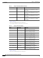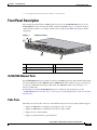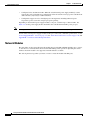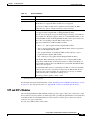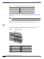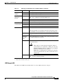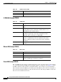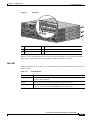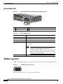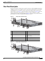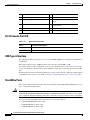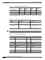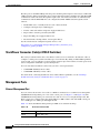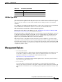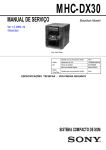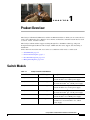
1
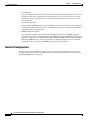
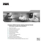
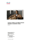
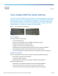
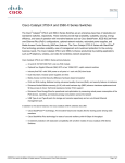
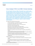
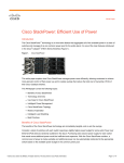
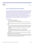
C H A P T E R
1
Product Overview
The Catalyst 3750-X and 3560-X series switches are Ethernet switches to which you can connect devices
such as Cisco IP Phones, Cisco Wireless Access Points, workstations, and other network devices such
as servers, routers, and other switches.
The Catalyst 3750-X switches support stacking through Cisco StackWise technology and power
management through StackPower. The Catalyst 3560-X switches do not support switch stacking or
StackPower.
Unless otherwise noted, the term switch refers to a standalone switch and to a switch stack.
•
Switch Models, page 1-1
•
Front Panel Description, page 1-3
•
Rear Panel Description, page 1-15
•
Management Options, page 1-21
Switch Models
Table 1-1
Catalyst 3750-X Switch Models
Switch Model
Cisco IOS Image
Description
Catalyst 3750-X-24T-L
LAN Base image
24 10/100/1000 Ethernet ports, StackWise Plus, 1
network module1 slot, 350-W power supply
Catalyst 3750-X-48T-L
LAN Base image
48 10/100/1000 Ethernet ports, StackWise Plus,
one network module1 slot, 350-W power supply
Catalyst 3750-X-24P-L
LAN Base image
24 10/100/1000 PoE+2 ports, StackWise Plus, 1
network module1 slot, 715-W power supply
Catalyst 3750-X-48P-L
LAN Base image
48 10/100/1000 PoE+2 ports, StackWise Plus,
one network module1 slot, 715-W power supply
Catalyst 3750-X-48PF-L LAN Base image
48 10/100/1000 PoE+2 ports, StackWise Plus, 1
network module1 slot, 1100-W power supply
Catalyst 3750-X-24T-S
IP Base image3
24 10/100/1000 Ethernet ports, StackWise Plus,
StackPower, 1 network module1 slot, 350-W
power supply
Catalyst 3750-X and 3560-X Switch Hardware Installation Guide
OL-19593-01
1-1
Chapter 1
Product Overview
Switch Models
Table 1-1
Catalyst 3750-X Switch Models (continued)
Switch Model
Cisco IOS Image
3
Description
Catalyst 3750-X-48T-S
IP Base image
48 10/100/1000 Ethernet ports, StackWise Plus,
StackPower, 1 network module1 slot, 350-W
power supply
Catalyst 3750-X-24P-S
IP Base image3
24 10/100/1000 PoE+2 ports, StackWise Plus,
StackPower, 1 network module1 slot, 715-W
power supply
Catalyst 3750-X-48P-S
IP Base image3
48 10/100/1000 PoE+2 ports, StackWise Plus,
StackPower, 1 network module1 slot, 715-W
power supply
Catalyst 3750-X-48PF-S IP Base image3
48 10/100/1000 PoE+2 ports, StackWise Plus,
StackPower, 1 network module1 slot, 1100-W
power supply
1. Available network modules: 10-Gigabit Ethernet network module; 1-Gigabit Ethernet network module; blank module (see
Table 1-3 on page 1-5).
2. PoE+ = Power over Ethernet plus (provides up to 30 W per port).
3. You can upgrade to the IP Services feature set when you order the switch.
Table 1-2
Catalyst 3560-X Switch Models
Switch
Part Number
Description
Catalyst 3560-X-24T-L
LAN Base image
24 10/100/1000 Ethernet ports, 1 network
module1 slot, 350-W power supply
Catalyst 3560-X-48T-L
LAN Base image
48 10/100/1000 Ethernet ports, 1 network
module1 slot, 350-W power supply
Catalyst 3560-X-24P-L
LAN Base image
24 10/100/1000 PoE+2 ports, 1 network
module1 slot, 715-W power supply
Catalyst 3560-X-48P-L
LAN Base image
48 10/100/1000 PoE+2 ports, 1 network
module1 slot, 715-W power supply
Catalyst 3560-X-48PF-L LAN Base image
48 10/100/1000 PoE+2 ports, 1 network
module1 slot, 1100-W power supply
Catalyst 3560-X-24T-S
IP Base image3
24 10/100/1000 Ethernet ports, 1 network
module1 slot, 350-W power supply
Catalyst 3560-X-48T-S
IP Base image3
48 10/100/1000 Ethernet ports, 1 network
module1 slot, 350-W power supply
Catalyst 3560-X-24P-S
IP Base image3
24 10/100/1000 PoE+2 ports, 1 network
module1 slot, 715-W power supply
Catalyst 3560-X-48P-S
IP Base image3
48 10/100/1000 PoE+2 ports, 1 network
module1 slot, 715-W power supply
Catalyst 3560-X-48PF-S
IP Base image3
48 10/100/1000 PoE+2 ports, 1 network
module1 slot, 1100-W power supply
1. Available network modules: 10-Gigabit Ethernet network module; 1-Gigabit Ethernet network module; blank module (see
Table 1-3 on page 1-5).
2. PoE+ = Power over Ethernet plus (provides up to 30 W per port).
Catalyst 3750-X and 3560-X Switch Hardware Installation Guide
1-2
OL-19593-01
Chapter 1
Product Overview
Front Panel Description
3. You can upgrade to the IP Services feature set when you order the switch.
Front Panel Description
The switch front panel includes a USB Type B console port, the 10/100/1000 Ethernet ports or the
10/100/1000 PoE+ ports, the network module, and the switch LEDs. Figure 1-1 shows the Catalyst
3750-X-48 PoE+ switch as an example. All the Catalyst 3750-X and 3560-X switches have similar
components.
Figure 1-1
Switch Front Panel
2
3
1
MODE
CONSO
LE
XPS
STAT
S-PWR
SPEED
MAST
STACK
1
2
3
4
5
6
7
8
9
10
DUPLX
PoE
11
12
13
14
15
16
17
18
19
20
21 22
23
C3KX-N
24
25
26
M-10G
27
28
29
30
31
32
33 34
35
NETWO
RK
MODULE
251960
SYST
EN
36
37
38
39
40
41
42
43
44
45
Catalyst 46
3750-X 47 48
PoE+48
G1
G2/TE1
4
G3
G4/TE2
5
1
Mode button
4
10/100/1000 ports
2
USB Type B console port
5
Network Module
3
Status LEDs
10/100/1000 Ethernet Ports
The 10/100/1000 Ethernet ports use RJ-45 connectors with Ethernet pinouts. The maximum cable length
is 328 feet (100 meters). The 100BASE-TX and 1000BASE-T traffic requires Category 5, Category 5e,
or Category 6 unshielded twisted pair (UTP) cable. The 10BASE-T traffic can use Category 3 or
Category 4 UTP cable.
For information about the 10/100/1000 Ethernet port connections and specifications, see the
“10/100/1000 Ethernet Port Connections” section on page 2-26 and Appendix B, “Connector and Cable
Specifications.”
PoE+ Ports
The PoE+ ports use the same connectors as described in the previous section and provide this support.
•
Support for IEEE 802.3af compliant powered devices (up to 15.4 W)
•
Support for IEEE 802.3at compliant powered devices (up to 30 W)
•
Support for Cisco enhanced PoE
•
Support for prestandard Cisco powered devices
Catalyst 3750-X and 3560-X Switch Hardware Installation Guide
OL-19593-01
1-3
Chapter 1
Product Overview
Front Panel Description
•
Configuration for StackPower PoE+. When the switch internal power supply module(s) cannot
support the total load, StackPower configurations allow the switch to leverage power available from
other switches (only Catalyst 3750-X switches)
•
Configurable support for Cisco intelligent power management, including enhanced power
negotiation, power reservation, and per-port power policing
Depending on the installed power supply modules, each port can deliver up to 30 W of PoE+. See
Table 1-17 for the power supply matrix that defines the available PoE and PoE+ power per port.
Note
The output of the PoE+ circuit has been evaluated as a Limited Power Source (LPS) per IEC 60950-1.
For information about power supply modules, PoE+ port connections, and PoE+ specifications, see the
“Power Supply Modules” section on page 1-17, the “PoE+ Port Connections” section on page 2-26, and
Appendix B, “Connector and Cable Specifications.”
Network Modules
The switch has one hot-swappable network module that provides SFP and SFP+ uplink ports to connect
to other devices. You must insert the network module during switch operation. Operating the switch
without a network module is not supported. A blank module is available.
The switch generates logs when you insert or remove a network module with SFP ports.
Catalyst 3750-X and 3560-X Switch Hardware Installation Guide
1-4
OL-19593-01
Chapter 1
Product Overview
Front Panel Description
Table 1-3
Network Modules
Network Module1
Description
Blank
This module has no uplink ports.
1-Gigabit Ethernet
This module has four 1-Gigabit SFP module slots. Any combination of standard
SFP modules are supported. SFP+ modules are not supported.
If you insert an SFP+ module in the 1-Gigabit network module, the SFP+
module does not operate, and the switch logs an error message.
10-Gigabit Ethernet
This module has four slots. Two slots support only 1-Gigabit SFP modules, two
slots support either 1-Gigabit SFP or 10-Gigabit SFP+ modules.
The four slots are grouped as two pairs with each pair consisting of one SFP slot
and one SFP+ slot. Each pair supports either two 1-Gigabit SFP modules or one
10-Gigabit SFP+ module. A 10-Gigabit SFP+ module cannot operate at the same
time as the corresponding 1-Gigabit SFP module in the pair.
Supported combinations of SFP and SFP+ modules:
•
Slots 1, 2, 3, and 4 populated with 1-Gigabit SFP modules.
•
Slots 1 and 2 populated with 1-Gigabit SFP modules and Slot 4 populated
with one 10-Gigabit SFP+ module.
•
Slot 2 populated with one 10-Gigabit SFP+ module and Slots 3 and 4
populated with 1-Gigabit SFP modules.
•
Slot 2 and Slot 4 each populated with 10-Gigabit SFP+ modules.
A 10-Gigabit SFP+ module takes precedence over a 1-Gigabit SFP module
except when an SFP module is first inserted in Slot 1 and has link. When you
insert an SFP+ module in Slot 2, the SFP in Slot 1 retains link. The SFP+ module
in Slot 2 does not operate.
When the SFP module in Slot 1 is shutdown, loses link, or is removed, the SFP+
module in Slot 2 becomes operational. At this point, the SFP module in Slot 1
will not become operational under any circumstance for as long as an SFP+
module remains in Slot 2 whether it is link up or not.
The same precedence applies to Slots 3 and 4.
1. All network modules are hot-swappable.
For information about the network modules, see the “Installing a Network Module in the Switch” section
on page 2-21. For cable specifications, see Appendix B, “Connector and Cable Specifications.”
SFP and SFP+ Modules
The switch-Gigabit Ethernet SFP and SFP+ modules provide copper or fiber-optic connections to other
devices. These transceiver modules are field-replaceable, providing the uplink interfaces when installed
in an SFP module slot. The SFP modules have LC connectors for fiber-optic connections or RJ-45
connectors for copper connections.
Use only Cisco SFP modules on the switch.
Catalyst 3750-X and 3560-X Switch Hardware Installation Guide
OL-19593-01
1-5
Chapter 1
Product Overview
Front Panel Description
Table 1-4
Cisco SFP Modules Supported for the 3750-X and 3560-X Switches
Part Number
Description
GLC-GE-100FX=
100FX SFP on GE SFP ports for LAN switches1
GLC-LH-SM=
GE SFP, LC connector LX/LH transceiver
GLC-SX-MM=
GE SFP, LC connector SX transceiver
GLC-T=
1000BASE-T SFP transceiver module for copper connections1
GLC-ZX-SM=
1000BASE-ZX SFP module for SMF, 1550 nm
GLC-BX-D=
1000BASE-BX10 SFP module for single-strand SMF, 1490-nm TX,
1310-nm RX wavelength
GLC-BX-U=
1000BASE-BX10 SFP module for single-strand SMF, 1310-nm TX,
1490-nm RX wavelength
CWDM-SFP-1470=
CWDM 1470-nm SFP Gigabit Ethernet and 1G/2G FC
CWDM-SFP-1490=
CWDM 1490-nm SFP Gigabit Ethernet and 1G/2G FC
CWDM-SFP-1510=
CWDM 1510-nm SFP Gigabit Ethernet and 1G/2G FC
CWDM-SFP-1530=
CWDM 1530-nm SFP Gigabit Ethernet and 1G/2G FC
CWDM-SFP-1550=
CWDM 1550-nm SFP Gigabit Ethernet and 1G/2G FC
CWDM-SFP-1570=
CWDM 1570-nm SFP Gigabit Ethernet and 1G/2G FC
CWDM-SFP-1590=
CWDM 1590-nm SFP Gigabit Ethernet and 1G/2G FC
CWDM-SFP-1610=
CWDM 1610-nm SFP Gigabit Ethernet and 1G/2G FC
SFP-GE-S=
1000BASE-SX SFP module for MMF, 850 nm (DOM)2
SFP-GE-L=
1000BASE-LX/LH SFP module for SMF, 1300 nm (DOM)2
DWDM-SFP-3033=
DWDM SFP 1530.33-nm SFP (100 GHz ITU grid)
DWDM-SFP-3112=
DWDM SFP 1531.12-nm SFP (100 GHz ITU grid)
DWDM-SFP-3190=
DWDM SFP 1531.90-nm SFP (100 GHz ITU grid)
DWDM-SFP-3268=
DWDM SFP 1532.68-nm SFP (100 GHz ITU grid)
DWDM-SFP-3346=
DWDM SFP 1533.47-nm SFP (100 GHz ITU grid)
DWDM-SFP-3425=
DWDM SFP 1534.25-nm SFP (100 GHz ITU grid)
DWDM-SFP-3504=
DWDM SFP 1535.04-nm SFP (100 GHz ITU grid)
DWDM-SFP-3582=
DWDM SFP 1535.82-nm SFP (100 GHz ITU grid)
DWDM-SFP-3661=
DWDM SFP 1536.61-nm SFP (100 GHz ITU grid)
DWDM-SFP-3739=
DWDM SFP 1537.40-nm SFP (100 GHz ITU grid)
DWDM-SFP-3819=
DWDM SFP 1538.19-nm SFP (100 GHz ITU grid)
DWDM-SFP-3898=
DWDM SFP 1538.98-nm SFP (100 GHz ITU grid)
DWDM-SFP-3977=
DWDM SFP 1539.77-nm SFP (100 GHz ITU grid)
DWDM-SFP-4056=
DWDM SFP 1540.56-nm SFP (100 GHz ITU grid)
DWDM-SFP-4134=
DWDM SFP 1541.35-nm SFP (100 GHz ITU grid)
DWDM-SFP-4214=
DWDM SFP 1542.14-nm SFP (100 GHz ITU grid)
DWDM-SFP-4294=
DWDM SFP 1542.94-nm SFP (100 GHz ITU grid)
Catalyst 3750-X and 3560-X Switch Hardware Installation Guide
1-6
OL-19593-01
Chapter 1
Product Overview
Front Panel Description
Table 1-4
Cisco SFP Modules Supported for the 3750-X and 3560-X Switches (continued)
Part Number
Description
DWDM-SFP-4373=
DWDM SFP 1543.73-nm SFP (100 GHz ITU grid)
DWDM-SFP-4453=
DWDM SFP 1544.53-nm SFP (100 GHz ITU grid)
DWDM-SFP-4532=
DWDM SFP 1545.32-nm SFP (100 GHz ITU grid)
DWDM-SFP-4612=
DWDM SFP 1546.12-nm SFP (100 GHz ITU grid)
DWDM-SFP-4692=
DWDM SFP 1546.92-nm SFP (100 GHz ITU grid)
DWDM-SFP-4772=
DWDM SFP 1547.72-nm SFP (100 GHz ITU grid)
DWDM-SFP-4851=
DWDM SFP 1548.51-nm SFP (100 GHz ITU grid)
DWDM-SFP-4931=
DWDM SFP 1549.32-nm SFP (100 GHz ITU grid)
DWDM-SFP-5012=
DWDM SFP 1550.12-nm SFP (100 GHz ITU grid)
DWDM-SFP-5092=
DWDM SFP 1550.92-nm SFP (100 GHz ITU grid)
DWDM-SFP-5172=
DWDM SFP 1551.72-nm SFP (100 GHz ITU grid)
DWDM-SFP-5252=
DWDM SFP 1552.52-nm SFP (100 GHz ITU grid)
DWDM-SFP-5332=
DWDM SFP 1553.33-nm SFP (100 GHz ITU grid)
DWDM-SFP-5413=
DWDM SFP 1554.13-nm SFP (100 GHz ITU grid)
DWDM-SFP-5494=
DWDM SFP 1554.94-nm SFP (100 GHz ITU grid)
DWDM-SFP-5575=
DWDM SFP 1555.75-nm SFP (100 GHz ITU grid)
DWDM-SFP-5655=
DWDM SFP 1556.55-nm SFP (100 GHz ITU grid)
DWDM-SFP-5736=
DWDM SFP 1557.36-nm SFP (100 GHz ITU grid)
DWDM-SFP-5817=
DWDM SFP 1558.17-nm SFP (100 GHz ITU grid)
DWDM-SFP-5898=
DWDM SFP 1558.98-nm SFP (100 GHz ITU grid)
DWDM-SFP-5979=
DWDM SFP 1559.79-nm SFP (100 GHz ITU grid)
DWDM-SFP-6061=
DWDM SFP 1560.61-nm SFP (100 GHz ITU grid)
DWDM-SFP-6141=
DWDM SFP 1561.42-nm SFP (100 GHz ITU grid)
1. Not supported for NEBS.
2. DOM = digital optical monitoring.
l
Table 1-5
Cisco SFP+ Modules Supported for the 3750-X and 3560-X Switches
Part Number
Description
SFP-10G-LR=
10 GBASE LR SFP+ transceiver module for SMF,
1350 nm, LC duplex connector
SFP-10G-SR=
10 GBASE SR SFP+ transceiver module for
MMF, 850 nm, LC duplex connector
SFP-10G-LRM=
10 GBASE-LRM SFP+ module for MMF and
SMF, 1310 nm
SFP-H10GB-CU1M=
10 GBASE-CU Twinax SFP+ cable assembly, 1
meter
Catalyst 3750-X and 3560-X Switch Hardware Installation Guide
OL-19593-01
1-7
Chapter 1
Product Overview
Front Panel Description
Table 1-5
Cisco SFP+ Modules Supported for the 3750-X and 3560-X Switches
Part Number
Description
SFP-H10GB-CU3M=
10 GBASE-CU Twinax SFP+ cable assembly, 3
meters
SFP-H10GB-CU5M=
10 GBASE-CU Twinax SFP+ cable assembly,
5meters
For information about SFP modules, see your SFP module documentation and the “Installing SFP and
SFP+ Modules” section on page 2-23. For cable specifications, see Appendix B, “Connector and Cable
Specifications.”
When ordering or using CX1 cables, ensure that the version identifier is 2 or higher.
Note
The Catalyst 3560-X switch supports the SFP module patch cable (CAB-SFP-50CM), a 0.5-meter,
copper, passive cable with SFP module connectors at each end. This cable is only used with 1-Gigabit
Ethernet SFP ports to connect two Catalyst 3560-X switches in a cascaded configuration.
LEDs
You can use the switch LEDs to monitor switch activity and its performance. Figure 1-2 shows the
Catalyst 3750-X switch LEDs and the Mode button that you use to select a port mode.
Switch Front Panel LEDs
1
MODE
2
3
SYST
XPS
EN
STAT
S-PWR
1
2
3
4
6
1
4
5
CONSOL
E
5
6
7
SPEED
MAST
7
8
STACK
8
9
9
System LED
1
DUPLX
PoE
10
11
12
251962
Figure 1-2
10
6
USB console port LED
2
XPS LED
7
S-PWR (StackPower) LED2
3
Status LED
8
Master LED2
4
Speed LED
9
Stack LED2
5
Duplex LED
10 PoE+ LED3
1. XPS = Expandable power system.
Catalyst 3750-X and 3560-X Switch Hardware Installation Guide
1-8
OL-19593-01
Chapter 1
Product Overview
Front Panel Description
2. Only Catalyst 3750-X switches.
3. Only switches with PoE+ ports.
System LED
Table 1-6
System LED
Color
System Status
Off
System is not powered on.
Green
System is operating normally.
Blinking Green
Switch is running power on self-test (POST).
Blinking Amber
There is a fault with one of the following:
Amber
•
Network module (non-traffic-related)
•
Power supply
•
Fan module
System is receiving power but is not functioning properly.
For information on the System LED colors during power-on self-test (POST), see the “Diagnosing
Problems” section on page 4-1.
XPS LED
Table 1-7
XPS LED
Color
XPS Status
Off
XPS cable is not installed.
Switch is in StackPower mode (Catalyst 3750-X).
Green
XPS is connected and ready to provide back-up power.
Blinking green
XPS is connected but is unavailable because it is providing power to another device
(redundancy has been allocated to a neighboring device).
Amber
The XPS is in standby mode or in a fault condition. See the XPS-2200
documentation for information about the standby mode and fault conditions.
Blinking amber
The power supply in a switch has failed, and the XPS is providing power to that
switch (redundancy has been allocated to this device).
Port LEDs and Modes
Each Ethernet port and 10-Gigabit Ethernet module slot has a port LED. These port LEDs, as a group or
individually, display information about the switch and about the individual ports. The port mode
determines the type of information shown by the port LEDs. Table 1-8 lists the mode LEDs and their
associated port modes and meanings.
To select or change a mode, press the Mode button until the desired mode is highlighted. When you
change port modes, the meanings of the port LED colors also change. Table 1-9 explains how to interpret
the port LED colors in different port modes.
Catalyst 3750-X and 3560-X Switch Hardware Installation Guide
OL-19593-01
1-9
Chapter 1
Product Overview
Front Panel Description
When you press the Mode button on any switch in the Catalyst 3750-X switch stack, all the stack
switches change to show the same selected mode. For example, if you press the Mode button on the stack
master to show the SPEED LED, all the other switches in the stack also show the SPEED LED.
Table 1-8
Port Mode LEDs
Mode LED
Port Mode
Description
STAT
Port status
The port status. This is the default mode.
SPEED
Port speed
The port operating speed: 10, 100, or 1000 Mb/s.
DUPLX
Port duplex mode
The port duplex mode: full duplex or half duplex.
Note
MAST1
STACK
1
PoE+2
The 10/100/1000 ports operate only in full-duplex
mode.
Master
The stack master status
Stack member status
The stack member status.
StackWise port status
The StackWise port status. See the “Stack LED (Catalyst
3750-X)” section on page 1-12.
PoE+ port power
The PoE+ port status.
1. Only Catalyst 3750-X switches.
2. Only switches with PoE+ ports.
Table 1-9
Meaning of Switch LED Colors in Different Modes
Port Mode
Port LED Color
Meaning
STAT
(port status)
Off
No link, or port was administratively shut down.
Green
Link present, no activity.
Blinking green Activity. Port is sending or receiving data.
Alternating
green-amber
Link fault. Error frames can affect connectivity, and errors such as
excessive collisions, CRC errors, and alignment and jabber errors
are monitored for a link-fault indication.
Amber
Port is blocked by Spanning Tree Protocol (STP) and is not
forwarding data.
After a port is reconfigured, the port LED can be amber for up to 30
seconds as STP checks the switch for possible loops.
SPEED
10/100/1000 ports
Off
Port is operating at 10 Mb/s.
Green
Port is operating at 100 Mb/s.
Port is operating at 1000 Mb/s.
Single green
flash (on for
100 ms, off for
1900 ms)
Network module slots
Off
Port is not operating.
Blinking green Port is operating at up to 10 Gb/s.
Catalyst 3750-X and 3560-X Switch Hardware Installation Guide
1-10
OL-19593-01
Chapter 1
Product Overview
Front Panel Description
Table 1-9
Meaning of Switch LED Colors in Different Modes (continued)
Port Mode
Port LED Color
Meaning
DUPLX
(duplex)
Off
Port is operating in half duplex.
Green
Port is operating in full duplex.
MAST1
(data stack
master)
Off
The switch is not the stack master.
For a standalone switch, this LED is off.
Note
Green
The switch is the stack master.
Amber
Error during stack master election.
1
STACK
Off
No stack member corresponding to that member number.
(stack member) Blinking green Stack member number.
PoE+2
Green
Member numbers of other stack member switches.
Off
PoE+ is off.
If the powered device is receiving power from an AC power source,
the port LED is off even if the device is connected to the switch port.
Green
PoE+ is on. The port LED is green when the switch port is providing
power.
Alternating
green and
amber
PoE+ is denied because providing power to the powered device will
exceed the switch power capacity.
Blinking amber PoE+ is off due to a fault or because it has exceeded a limit set in
the switch software.
Caution
Amber
PoE+ faults are caused when noncompliant cabling or
powered devices are connected to a PoE+ port. Use only
standard-compliant cabling to connect Cisco prestandard
IP Phones and wireless access points or
IEEE 802.3af-compliant devices to PoE+ ports. You must
remove from the network any cable or device that causes
a PoE+ fault.
PoE+ for the port has been disabled.
Note
PoE+ is enabled by default.
1. Only Catalyst 3750-X switches.
2. Only switches with PoE or PoE+ ports.
USB Console LED
The USB console LED shows whether there is an active USB connection to the port.
Catalyst 3750-X and 3560-X Switch Hardware Installation Guide
OL-19593-01
1-11
Chapter 1
Product Overview
Front Panel Description
Table 1-10
USB Console Port LED
Color
Description
Off
USB console is disabled.
Green
USB console is enabled.
S-PWR LED (Catalyst 3750-X)
Table 1-11
S-PWR LED
Color
Description
Off
StackPower cable is not connected, or the switch is in standalone
mode.
Green
An XPS cable is connected to the XPS-2200.
Each StackPower port is connected to another switch or to an
XPS-2200 (Catalyst 3750-X switches).
Blinking Green
This appears on the switch in a StackPower ring configuration
that detects an open ring or has only one StackPower cable
connected, and no connection to an XPS-2200.
Amber
There is a fault: load shedding is occurring, a StackPower cable is
defective, or administrative action is required. See the switch
software configuration guide for information about configuring
StackPower.
Blinking Amber
The StackPower budget is not sufficient to meet current power
demands.
Master LED (Catalyst 3750-X)
Table 1-12
Master LED
Color
Description
Off
Switch is not the stack master.
Green
Switch is the stack master or a standalone switch.
Amber
An error occurred when the switch was selecting the stack master
switch, or another type of stack error occurred.
Stack LED (Catalyst 3750-X)
The stack LED shows the sequence of member switches in a stack. Up to nine switches can be members
of a stack. The first nine port LEDs show the member number of a switch in a stack. Figure 1-3 shows
the LEDs on the first switch, which is stack member number 1. For example, if you press the Mode
button and select Stack, the LED for port 1 blinks green. The LEDs for ports 2 and 3 are solid green, as
these represent the member numbers of other switches in the stack. The other port LEDs are off because
there are no more members in the stack.
Catalyst 3750-X and 3560-X Switch Hardware Installation Guide
1-12
OL-19593-01
Chapter 1
Product Overview
Front Panel Description
Figure 1-3
Stack LED
MODE
CONSO
LE
SYST
XPS
EN
SYST
XPS
STAT
EN
S-PWR
SPEED
2
MODE
3
4
5
6
7
8
CONSO
LE
SYST
XPS
STAT
EN
S-PWR
9
10
11
MODE
4
5
6
7
8
CONSO
LE
SYST
3
4
5
6
7
PoE
8
9
10
11
C3KX-N
12
2
3
4
5
6
1
7
8
9
10
2
11
3
STAT
S-PWR
9
10
SPEED
MAST
STACK
11
12
2
3
4
DUPLX
5
6
7
8
PoE
9
10
11
4
12
1
2
3
4
2
3
4
5
6
7
8
9
10
11
2
5
6
7
8
5
3
4
5
5
6
6
7
8
7
9
9
10
11
3
4
5
6
7
8
9
10
11
G1
2
3
4
5
6
7
8
11
G2/TE1
G3
M-10G
G1
G2/TE1
C3KX-N
2
3
4
5
6
7
8
9
10
11
2
12
G4/TE2
NETWO
RK
MODULE
3
9
12
1
M-10G
10
NETWO
RK
MODULE
12
Catalyst 10
3750-X 11 12
PoE+48
2
9
C3KX-N
12
1
8
6
1
1
4
12
Catalyst 10
3750-X 11 12
PoE+48
1
XPS
EN
PoE
1
2
DUPLX
1
3
DUPLX
STACK
12
1
SPEED
MAST
1
2
SPEED
PoE
STACK
1
MAST
DUPLX
MAST
STACK
1
STAT
S-PWR
CONSO
LE
G3
M-10G
G4/TE2
NETWO
RK
MODULE
253198
MODE
12
1
2
3
4
5
6
7
8
9
Catalyst 10
3750-X 11 12
PoE+48
G1
G2/TE1
G3
G4/TE2
1
Stack member 1
4
LED blinks green to show that this is switch 1 in the stack.
2
Stack member 2
5
LED is solid green to show that switch 2 is a stack member.
3
Stack member 3
6
LED is solid green to show that switch 3 is a stack member.
When you select the Stack LED mode, the representative Stack LEDs are green when the StackWise
ports are up, and the representative Stack LEDs are amber when the ports are down.
PoE+ LED
If the PoE+ LED mode is not selected on a switch with PoE+ ports, the PoE+ LED still shows detected
PoE+ problems.
Table 1-13
PoE+ Mode LED
Color
PoE+ Status
Off
PoE+ mode is not selected. None of the 10/100/1000 ports have been denied power
or are in a fault condition.
Green
PoE+ mode is selected, and the port LEDs show the PoE+ status.
Blinking amber
PoE+ mode is not selected. At least one of the 10/100/1000 ports has been denied
power, or at least one of the 10/100/1000 ports has a PoE+ fault.
Catalyst 3750-X and 3560-X Switch Hardware Installation Guide
OL-19593-01
1-13
Chapter 1
Product Overview
Front Panel Description
Network Module LEDs
Figure 1-4
Network Module LEDs (10-Gigabit Network Module Shown)
C3KX-N
NETWOR
MODULEK
37
38
39
40
41
42
43
44
253212
M-10G
45
Catalys 46
t 3750-X 47 48
PoE+48
G1
G2/TE1
G3
G4/TE2
1 2
3 4
1
G1 LED
3
G3 LED
2
G2/TE1 LED
4
G4/TE2 LED
Table 1-14
Network Module LEDs
Color
Network Module Link Status
Off
Link is off.
Green
Link is on, no activity.
Blinking green
Activity on a link, no faults.
Blinking amber
Link is off due to a fault or because it has exceeded a limit set in the
switch software.
Caution
Amber
Link faults are caused when noncompliant cabling is
connected to an SFP or SFP+ port. Use only
standard-compliant cabling to connect to Cisco SFP and
SFP+ ports. You must remove from the network any cable
or device that causes a link fault.
Link for the SFP or SFP+ has been disabled.
USB Mini-Type B Port
A USB 5-pin mini-Type B connector on the front panel is available for switch management (Figure 1-5).
USB Mini-Type B Console Port
253163
Figure 1-5
See the “Management Ports” section on page 1-20 for details.
Catalyst 3750-X and 3560-X Switch Hardware Installation Guide
1-14
OL-19593-01
Chapter 1
Product Overview
Rear Panel Description
Rear Panel Description
The switch rear panel has a ground connector, an RJ-45 console port, an RJ-45 10/100 management port,
a USB Type A connector, two StackWise connectors (only Catalyst 3750-X switches), two fan modules,
an XPS-2200 connector, a StackPower connector (only Catalyst 3750-X switches), and two power
supply module slots. See Figure 1-6, and the descriptions on the following pages. Figure 1-6 shows the
Catalyst 3750-X-48 PoE+ switch, which has one connector for either a StackPower or an XPS
connection, and one connector only for StackPower. Figure 1-7 shows the Catalyst 3560-X switch rear
panel, which has one connector for XPS and no StackPower connector.
Figure 1-6
Catalyst 3750-X Switch Rear Panel
3
2
5
9
4
11
7
1
CONSOL
E
AUX
STACK
1
RESET
STACK
2
S-PWR
XPS
AC OK
PS OK
C3KX-P
WR-715
WAC
AC OK
PS OK
C3KX-P
WR-715
WAC
251961
S-PWR
6
8
10
12 13
12 13
1
Ground connector
8
Fan modules
2
RJ 45 console port LED
9
StackPower or XPS-2200 connector
3
RJ-45 console port
10 StackPower connector
4
RJ-45 10/100 management port
11 Power supply modules (AC power supply
modules shown)
5
USB Type A connector
12 AC power (input) status LED
6
Stack cable connectors
13 Power supply (output) status LED
7
Reset button
Figure 1-7
2
Catalyst 3560-X Switch Rear Panel
3
8
5
4
10
6
1
CONSOL
E SERIAL
10/100T
X
RESET
XPS
AC OK
C3KX-P
WR-715
WAC
253392
PS OK
7
9
11 12
Catalyst 3750-X and 3560-X Switch Hardware Installation Guide
OL-19593-01
1-15
Chapter 1
Product Overview
Rear Panel Description
1
Ground connector
7
Fan modules
2
RJ-45 console port LED
8
XPS-2200 connector
3
RJ-45 console port
9
Power supply module slot (blank module
shown)
4
RJ-45 10/100 management port
10 Power supply module (AC power supply
module shown)
5
USB Type A connector
11 AC power (input) status LED
6
Reset button
12 Power supply (output) status LED
RJ-45 Console Port LED
Table 1-15
RJ-45 Console Port LED
Color
RJ-45 Console Port Status
Off
RS-232 console is disabled.
Green
RS-232 console is enabled.
USB Type A Interface
The USB Type A interface provides access to external USB FLASH devices (also known as thumb drives
or USB keys).
The interface supports Cisco USB flash drives with capacities from 64 MB to 1 GB.
Cisco IOS software provides standard file system access to the flash device: read, write, erase, and copy,
as well as formatting of the flash device with a FAT file system. You can boot the switch from a USB
drive.
For information about the switch management ports, see the switch software configuration guide and the
command reference on Cisco.com and the “Connector and Cable Specifications” section on page B-1.
StackWise Ports
The Catalyst 3750-X switch ships with a 0.5-meter StackWise cable (CAB-STACK-50CM) that you can
use to connect the StackWise ports.
Caution
Use only approved cables (CAB-STACK-50CM, CAB-STACK-1M, CAB-STACK-3M,
CAB-STACK-50CM-NH,CAB-STACK-1M-NH, or CAB-STACK-3M-NH), and connect only to similar
Cisco equipment. Equipment might be damaged if connected to nonapproved Cisco cables or equipment.
You can order these StackWise cables from your Cisco sales representative:
•
CAB-STACK-50CM (0.5-meter cable)
•
CAB-STACK-1M= (1-meter cable)
•
CAB-STACK-3M= (3-meter cable)
Catalyst 3750-X and 3560-X Switch Hardware Installation Guide
1-16
OL-19593-01
Chapter 1
Product Overview
Rear Panel Description
•
CAB-STACK-50CM-NH= (0.5-meter cable, nonhalogen)
•
CAB-STACK-1M-NH= (1-meter cable, nonhalogen)
•
CAB-STACK-3M-NH= (3-meter cable, nonhalogen)
Power Supply Modules
The 24- and 48-port switches are powered through one or two internal power supply modules. The
“Switch Power Supply Modules” section on page 1-17 and Table 1-16 describe the supported power
supply modules.
Switch Power Supply Modules
The switch has two internal power supply module slots. You can use two AC modules, two DC modules,
a mixed configuration of one AC and one DC power supply module, or one power supply module and a
blank module.
The switch can operate with either one or two active power supply modules or with power supplied by
an XPS-2200. A Catalyst 3750-X switch that is in a StackPower stack can operate with power supplied
by other switches in the stack.
Table 1-1 and Table 1-2 show the power supply modules that ship with each switch model. All power
supply modules (except the blank modules) have internal fans. All switches ship with a blank power
supply module in the second power supply slot.
Caution
Do not operate the switch with one power supply module slot empty. For proper chassis cooling, both
power supply module slots must be populated.
The 350-W and 715-W AC power supply modules are autoranging units that support input voltages
between 100 and 240 VAC. The 1100-W power supply module is an autoranging unit that supports input
voltages between 115 and 240 VAC. The 440-W DC power supply module has dual input feeds (A and
B) and supports input voltages between 36 and 72 VDC. The output voltage range is 51–57 V.
Each AC power supply module has a power cord for connection to an AC power outlet. The 1100-W and
715-W modules use a 16-AWG cord (only North America). All other modules use an 18-AWG cord. The
DC-power supply module must be wired to a DC-power source.
The XPS-2200 powers connected switches when the power supply is removed or fails. When a new
switch power supply is installed, the switch software polls the device. The switch power supply again
provides power, and the XPS-2200 is available to power other devices.
Table 1-16 shows the power supply modules available for Catalyst 3750-X and 3560-X switches and
power supply configurations based on switch models.
Table 1-16
Switch Power Supply Modules
Power Supply Module
48-Port PoE+
Switch1
48-Port
Non-PoE+
Switch
24-Port
Non-PoE+
Switch
Spare
Spare
Primary or spare Spare
Spare
24-Port PoE+
Switch
C3KX-PWR-1100WAC=
Primary or spare Spare
C3KX-PWR-1100WAC-JP=2
C3KX-PWR-715WAC=
Spare
Catalyst 3750-X and 3560-X Switch Hardware Installation Guide
OL-19593-01
1-17
Chapter 1
Product Overview
Rear Panel Description
Table 1-16
Switch Power Supply Modules (continued)
Power Supply Module
48-Port PoE+
Switch1
24-Port PoE+
Switch
48-Port
Non-PoE+
Switch
C3KX-PWR-350WAC=
Spare
Spare
Primary or spare Primary or spare
C3KX-PWR-440WDC=
Primary or spare Primary or spare Primary or spare Primary or spare
C3KX-PSBAY-BLNK
Blank module
Blank module
Blank module
24-Port
Non-PoE+
Switch
Blank module
1. For full 15.4 W support on a 48-port PoE+ switch, you must use a C3KX-PWR-1100WAC power supply module.
2. This module is used only in Japan.
Table 1-17
Switch Power Supply Requirements for PoE and PoE+
PoE Option
24-Port Switch
48-Port Switch
PoE (up to 15.4 W per port) (1) 715-W power supply
(1) 1100-W power supply
(2) 440-W DC power supplies
PoE+ (up to 30 W per port) (1) 1100-W power supply
Note
(1) 1100-W power supply plus one
715-W power supply
or
(2) 1100-W power supplies
A 48-port switch with one 715-W power supply provides up to 8.7 W of PoE to all ports.
The power supply modules have two status LEDs.
Table 1-18
Switch Power Supply Module LEDs
AC-Power Supply Module LEDs
AC OK
Description
PS OK
Description
Off
No AC input power.
Off
Output is disabled, or input is
outside operating range (AC LED
is off).
Green
AC input power present.
Green
Power output to switch active.
Red
Output has failed.
DC-Power Supply Module LEDs
DC OK
Description
PS OK
Description
Off
No DC input power.
Off
Output is disabled, or input is
outside operating range (DC LED
is off).
Green
DC input power present.
Green
Power output to switch active.
Red
Output has failed.
Catalyst 3750-X and 3560-X Switch Hardware Installation Guide
1-18
OL-19593-01
Chapter 1
Product Overview
Rear Panel Description
For information about replacing a power supply module, wiring a DC power supply module, and module
specifications, see Chapter 3, “Power Supply and Fan Module Installation,” and Appendix A, “Technical
Specifications.”
Fan Modules
The switch has two internal hot-swappable 12-V fan modules, each with two fans. The air circulation
system consists of the fan modules and the power supply modules. The airflow patterns vary depending
on the power supply configuration.
Figure 1-8 shows the airflow patterns for the 24- and 48-port switches. The blue arrow shows cool air
flow, and the red arrow shows warm air flow. When the fan modules are operating properly, a green LED
is on at the top left corner of the fan assembly (viewed from the rear). If the fan fails, the LED turns to
amber.
Figure 1-8
MODE
24- and 48-Port Switch Airflow Patterns
CONSO
LE
XPS
STAT
S-PWR
SPEED
MAST
STACK
1
2
3
4
5
6
7
8
9
10
DUPLX
PoE
11
12
1
2
3
4
5
6
7
8
9
10
11
C3KX-N
12
1
2
M-10G
3
4
5
6
7
8
9
10
11
NETWO
RK
MODULE
12
1
2
3
4
5
6
7
8
9
Catalyst 10
3750-X 11 12
PoE+48
G1
G2/TE1
G3
253199
SYST
EN
G4/TE2
For information about installing a fan module and the module specifications, see Chapter 3, “Power
Supply and Fan Module Installation,” and Appendix A, “Technical Specifications.”
XPS Connector
Warning
Attach only the following Cisco external power system to the switch: XPS 2200. Statement 387
The Cisco XPS-2200 is a expandable power system that can support nine network switches and provides
power to one or two failed switches at a time. It senses when the power supply of a connected switch
fails and provides power to the failed switch.
Use the XPS-2200 only with approved Cisco XPS cables. You can order these XPS cables for connecting
your switch to the XPS-2200 from your Cisco sales representative:
•
CAB-XPS-58CM (0.58-meter cable)
•
CAB-XPS-150CM (1.5-meter cable)
The Cisco XPS-2200 has a nominal output level of –56 V. The total maximum output power depends on
the installed power supply modules.
Catalyst 3750-X and 3560-X Switch Hardware Installation Guide
OL-19593-01
1-19
Chapter 1
Product Overview
Rear Panel Description
The nine ports on the XPS-2200 provide the power and management signals to the Catalyst 3750-X and
3560-X switches. Other switch models do not support this management communication. The XPS-2200
communicates with each switch through the 12-pin cable. All connected switches can simultaneously
communicate with the XPS-2200. You can configure these XPS-2200 features through the switch
software:
•
Enable XPS active or standby mode for each connected switch
•
Configure switch priority for XPS support
•
List the connected switches and power supply module sizes
•
Report when a switch is powered by the XPS
•
Report the XPS power supply module status
•
Read and monitor backup, failure, and exception history
See the switch software configuration guide on Cisco.com:
http://www.cisco.com/en/US/products/ps10745/products_installation_and_
configuration_guides_list.html
StackPower Connector (Catalyst 3750-X Switches)
The Catalyst 3750-X switches have a StackPower connector for use with Cisco StackPower cables to
configure a switch power stack that includes up to four switches. By adding an XPS-2200 expandable
power system, you can configure a power stack that comprises up to nine switches. A switch power stack
can be configured in redundant or power-sharing mode.
You can order these StackPower cables from your Cisco sales representative:
•
CAB-SPWR-30CM (0.3-meter cable)
•
CAB-SPWR-150CM (1.5-meter cable)
For details about connecting StackPower cables and StackPower guidelines, see the “Planning a
StackPower Stack (Catalyst 3750-X Switches)” section on page 2-8.
Management Ports
Ethernet Management Port
You can connect the switch to a host such as a Windows workstation or a terminal server through the
10/100 Ethernet management port or one of the console ports (see Figure 1-5 and Figure 1-6). The
10/100 Ethernet management port connection uses a RJ-45 crossover or straight-through cable. The
RJ-45 console port connection uses the supplied RJ-45-to-DB-9 female cable. The USB console port
uses a USB type-A-to-USB 5-pin mini-Type B cable.
Table 1-19 shows the Ethernet management port LED colors and their meanings.
Table 1-19
RJ-45 Console Port LED
Color
Description
Green
Active link to PC
Catalyst 3750-X and 3560-X Switch Hardware Installation Guide
1-20
OL-19593-01
Chapter 1
Product Overview
Management Options
Table 1-19
RJ-45 Console Port LED
Color
Description
Off
Inactive link
Amber
POST failure
USB Mini-Type B Port
The switch provides a USB mini-Type B console connection on the front panel, and the RJ-45 console
port on the switch rear panel. Console output is always active on both connectors, but console input is
active on only one connector at a time, with the USB connector taking precedence over the RJ-45
connector.
Use a USB type-A-to-USB 5-pin mini-Type B cable to connect a PC or other device to the switch. The
required USB cable is included in the optional accessory kit, (part number 800-33434).
The connected device must include a terminal emulation application.
Windows PCs need a driver for the USB port. See the “Installing the Cisco Microsoft Windows USB
Device Driver” section on page C-3 for installation instructions.
When the switch detects a valid USB connection to a powered device, input from the Ethernet connection
is immediately disabled, and input from the USB console is enabled. Removing the USB connection
immediately reenables input from the Ethernet connection. An LED on the switch front panel (see
Figure 1-2) is green when the USB console connection is enabled.
The switch provides a configurable inactivity timeout that reactivates the RJ-45 console if no input
activity has occurred on the USB console for a specified time period. After the USB console has been
deactivated due to a timeout, you can restore its operation by disconnecting and reconnecting the USB
cable. You can disable USB console operation by using Cisco IOS commands. See the switch software
configuration guide for details.
Management Options
•
Cisco Network Assistant
Cisco Network Assistant is a PC-based network management GUI application for LANs. You can
use the GUI to configure and manage switch clusters or standalone switches. Cisco Network
Assistant is available at no cost and can be downloaded from this URL:
http://www.cisco.com/go/networkassistant
For information on starting the Network Assistant application, see the Getting Started with Cisco
Network Assistant guide on Cisco.com.
•
Device manager
You can use the device manager in the switch memory to manage individual and standalone
switches. This web browser interface offers quick configuration and monitoring from anywhere in
your network. For information, see the switch getting started guide and the device manager online
help.
Catalyst 3750-X and 3560-X Switch Hardware Installation Guide
OL-19593-01
1-21
Chapter 1
Product Overview
Management Options
•
Cisco IOS CLI
You can configure and monitor the switch and switch cluster members from the CLI. You can access
the CLI by connecting your management station directly to the switch console port or by using
Telnet from a remote management station. See the switch command reference on Cisco.com for
more information.
•
CiscoWorks application
The CiscoWorks LAN Management Solution (LMS) is a suite of management tools that simplify the
configuration, administration, monitoring, and troubleshooting of Cisco networks. See the LMS
documentation for more information.
•
SNMP network management
You can manage switches from a Simple Network Management Protocol (SNMP)-compatible
management station that is running platforms such as HP OpenView or SunNet Manager. The switch
supports a comprehensive set of Management Information Base (MIB) extensions and four Remote
Monitoring (RMON) groups. See the switch software configuration guide on Cisco.com and the
documentation that came with your SNMP application for more information.
Network Configurations
See the switch software configuration guide on Cisco.com for network configuration concepts and
examples of using the switch to create dedicated network segments and interconnecting the segments
through Gigabit Ethernet connections.
Catalyst 3750-X and 3560-X Switch Hardware Installation Guide
1-22
OL-19593-01