1
SUPER
A
B
C
®
SC502 Chassis Series
D
E
F
G
H
I
J
K
L
DESCRI
REV
ª©¥»
1
2
3
4
5
6
SC502-200B
7
8
9
10
USER’S MANUAL
1.0
RANGE
½d³ò
TOLERANCE
¤½®t
X.xx
± 0.10
X.x
± 0.25
X
± 1.00
²Ä¤T¨¤ªk
THE 3RD PROJECTION
A BLEC
M
Ablecom Technology Inc.
MATERIAL / §÷½è :
*
FINISH / ªí-±³B¸Ì :
See Note.
UNIT / ³æ¦ì :
MM
¤j˚T¬ì§ÞªÑ¥÷
DRAWN / ø¹Ï :
SHO
DESIGN / ³]-p :
SHO
APPROVED / ¼f®Ö :
DATE / ¤é´Á:
13-Nov-07
DATE / ¤é´Á:
13-Nov-07
DATE / ¤é´Á:
SC502-200B Chassis Manual
The information in this User’s Manual has been carefully reviewed and is believed to be accurate.
The vendor assumes no responsibility for any inaccuracies that may be contained in this document,
makes no commitment to update or to keep current the information in this manual, or to notify any
person or organization of the updates. Please Note: For the most up-to-date version of this
manual, please see our web site at www.supermicro.com.
Super Micro Computer, Inc. ("Supermicro") reserves the right to make changes to the product
described in this manual at any time and without notice. This product, including software, if any,
and documentation may not, in whole or in part, be copied, photocopied, reproduced, translated or
reduced to any medium or machine without prior written consent.
IN NO EVENT WILL SUPERMICRO BE LIABLE FOR DIRECT, INDIRECT, SPECIAL, INCIDENTAL,
SPECULATIVE OR CONSEQUENTIAL DAMAGES ARISING FROM THE USE OR INABILITY TO
USE THIS PRODUCT OR DOCUMENTATION, EVEN IF ADVISED OF THE POSSIBILITY OF
SUCH DAMAGES. IN PARTICULAR, SUPERMICRO SHALL NOT HAVE LIABILITY FOR ANY
HARDWARE, SOFTWARE, OR DATA STORED OR USED WITH THE PRODUCT, INCLUDING THE
COSTS OF REPAIRING, REPLACING, INTEGRATING, INSTALLING OR RECOVERING SUCH
HARDWARE, SOFTWARE, OR DATA.
Any disputes arising between manufacturer and customer shall be governed by the
laws of Santa Clara County in the State of California, USA. The State of California, County of
Santa Clara shall be the exclusive venue for the resolution of any such disputes. Super Micro's
total liability for all claims will not exceed the price paid for the hardware product.
WARNING: Handling of lead solder materials used
in this product may expose you to lead, a chemical known
to the State of California to cause birth defects and other
reproductive harm.
Manual Revision 1.0
Release Date: December 6, 2007
Unless you request and receive written permission from Super Micro Computer, Inc., you may not
copy any part of this document.
Information in this document is subject to change without notice. Other products and companies
referred to herein are trademarks or registered trademarks of their respective companies or mark
holders.
Copyright © 2007 by Super Micro Computer, Inc.
All rights reserved.
Printed in the United States of America
ii
Preface
Preface
About This Manual
This manual is written for professional system integrators and PC technicians. It
provides information for the installation and use of the SC502 chassis. Installation
and maintenance should be performed by experienced technicians only.
Supermicro’s SC502 chassis features a unique and highly-optimized design for low
wattage processor platforms. The chassis is equipped with a 200W high efficiency
power supply for superb power savings. High performance fans provide ample
optimized cooling.
This document lists compatible parts available when this document was published.
Always refer to the our Web site for updates on supported parts and configurations.
iii
SC502 Chassis Manual
Manual Organization
Chapter 1 Introduction
The first chapter provides a checklist of the main components included with this
chassis and describes the main features of the SC502 chassis. This chapter also
includes contact information.
Chapter 2 System Safety
This chapter lists warnings, precautions, and system safety. It recommended that
you thoroughly familiarize yourself installing and servicing this chassis safety precautions.
Chapter 3 Chassis Components
Refer here for details on this chassis model including the fans, airflow shields, and
other components.
Chapter 4 Chassis Setup and Installation
Follow the procedures given in this chapter when installing, removing, or
reconfiguring your chassis.
Chapter 5 Rack Installation
Refer to this chapter for detailed information on chassis rack installation. You should
follow the procedures given in this chapter when installing, removing or reconfiguring
your chassis into a rack environment.
Appendix A Cables, Screws and other Accessories
Appendix B: Power Supply Specifications
iv
Preface
Table of Contents
Chapter 1 Introduction
1-1
1-2
Overview ......................................................................................................... 1-1
Shipping List.................................................................................................... 1-1
Part Numbers .................................................................................................. 1-1
1-3
Where to get Replacement Components........................................................ 1-2
1-4
Contacting SuperMicro .................................................................................... 1-3
Chapter 2 System Safety
2-1
Overview ......................................................................................................... 2-1
2-2
Warnings and Precautions .............................................................................. 2-1
2-3
Preparing for Setup ......................................................................................... 2-1
2-4
Electrical Safety Precautions .......................................................................... 2-2
2-5
General Safety Precautions ............................................................................ 2-3
2-6
System Safety ................................................................................................. 2-3
Chapter 3 Chassis Components
3-1
Overview ......................................................................................................... 3-1
3-2
Components .................................................................................................... 3-1
Chassis............................................................................................................ 3-1
Mounting to a Rack (optional) ......................................................................... 3-1
Power Supply .................................................................................................. 3-1
3-3
Where to get Replacement Components........................................................ 3-2
Chapter 4 Chassis Setup and Maintenance
4-1
Overview ......................................................................................................... 4-1
4-2
Removing the Chassis Cover ......................................................................... 4-2
4-3
Installing the Hard Drives ................................................................................ 4-3
4-4
Installing the Motherboard .............................................................................. 4-4
Chassis Standoffs ........................................................................................... 4-4
Motherboard Installation.................................................................................. 4-5
Add-on Card/Expansion Slot Setup ................................................................ 4-6
4-5
Replacing the Heatsink ................................................................................... 4-8
4-8
Power Supply ............................................................................................... 4-10
Checking the Server's Air Flow ....................................................................... 4-9
Replacing the Power Supply ......................................................................... 4-10
Chapter 5 Rack Installation
5-1
Overview ......................................................................................................... 5-1
5-2
Unpacking the System .................................................................................... 5-1
5-3
Preparing for Setup ......................................................................................... 5-1
v
Choosing a Setup Location ............................................................................. 5-1
Rack Precautions ............................................................................................ 5-2
General Server Precautions ............................................................................ 5-2
Rack Mounting Considerations ....................................................................... 5-3
Ambient Operating Temperature ................................................................ 5-3
Reduced Airflow ......................................................................................... 5-3
Mechanical Loading ................................................................................... 5-3
Circuit Overloading ..................................................................................... 5-3
5-4
Rack Mounting Instructions ............................................................................. 5-4
Installing the Chassis into a Rack: ................................................................. 5-4
Installing the Chassis into a Rack: ................................................................. 5-5
Appendix A Cables, Screws, and other Accessories
Appendix B Power Supply Specifications
vi
Chapter 1: Introduction
Chapter 1
Introduction
1-1
Overview
Supermicro’s SC502 chassis features a unique and highly-optimized design. The
chassis is equipped with high efficiency 80%+ low noise power supply.
1-2
Shipping List
Part Numbers
Please visit the following link for the latest shiping lists and part numbers for your
particular chassis model http://www.supermicro.com/
SC502-200B Chassis
Model
SC502-200(B)
CPU
HDD
I/O Slots
Intel Celeron 400
series (35W) or
low power platforms under 20W
1 Fixed 3.5"
hard drive or
up to 2 fixed
2.5" hard
drives
1x FH
(optional)
Power
Supply
200W
IMPORTANT: It is critical to choose the correct heatsink for your motherboard, that
will fit in the SC502 chassis.
1. Intel Celeron 400 seriew (35W) platform: Active heatsink SNKP0032A4
2. Low power platforms under 20W: Passive heatsink SNKP0016P
1-1
SC502 Chassis Manual
1-3
Where to get Replacement Components
Though not frequently, you may need replacement parts for your system. To ensure the highest level of professional service and technical support, we strongly
recommend purchasing exclusively from our Supermicro Authorized Distributors /
System Integrators / Resellers. A list of Supermicro Authorized Distributors / System
Integrators /Reseller can be found at: http://www.supermicro.com. Click the Where
to Buy link.
1-2
Chapter 1: Introduction
1-4
Contacting SuperMicro
Headquarters
Address:
Super Micro Computer, Inc.
980 Rock Ave.
San Jose, CA 95131 U.S.A.
Tel:
+1 (408) 503-8000
Fax:
+1 (408) 503-8008
Email:
[email protected] (General Information)
[email protected] (Technical Support)
Web Site:
www.supermicro.com
Europe
Address:
Super Micro Computer B.V.
Het Sterrenbeeld 28, 5215 ML
's-Hertogenbosch, The Netherlands
Tel:
+31 (0) 73-6400390
Fax:
+31 (0) 73-6416525
Email:
[email protected] (General Information)
[email protected] (Technical Support)
[email protected] (Customer Support)
Asia-Pacific
Address:
Super Micro Computer, Taiwan
4F, No. 232-1, Liancheng Rd.
Chung-Ho 235, Taipei County
Taiwan, R.O.C.
Tel:
+886-(2) 8226-3990
Fax:
+886-(2) 8226-3991
Web Site:
www.supermicro.com.tw
Email:
[email protected] (Technical Support)
Tel:
886-2-8228-1366, ext.132 or 139
1-3
SC502 Chassis Manual
Notes
1-4
Chapter 2: System Safety
Chapter 2
System Safety
2-1
Overview
This chapter provides a quick setup checklist to get your chassis up and running.
Following the steps in order given should enable you to have your chassis setup and
operational within a minimal amount of time. This quick set up assumes that you are
an experienced technician, famailiar with common concepts and terminology.
2-2
Warnings and Precautions
You should inspect the box the chassis was shipped in and note if it was damaged
in any way. If the chassis itself shows damage, file a damage claim with carrier
who delivered your system.
Decide on a suitable location for the rack unit that will hold that chassis. It should
be situated in a clean, dust-free area that is well venilated. Avoid areas where heat,
electrical noise and eletromagnetic fields are generated.
You will also need it placed near at least one grounded power outlet. When configured, the SC502 chassis includes one power supply.
2-3
Preparing for Setup
The SC502 Chassis bolts directly to a rack and includes the mounting screws you
will need to install the systems into the rack. Please read this manual in its entirety
before you begin the installation procedure.
2-1
SC502 Chassis Manual
2-4
Electrical Safety Precautions
Basic electrical safety precautions should be followed to protect yourself from harm
and the SC502 from damage:
•
•
•
•
•
•
•
•
Be aware of the locations of the power on/off switch on the chassis as well
as the room’s emergency power-off switch, disconnection switch or electrical
outlet. If an electrical accident occurs, you can then quickly remove power from
the system.
Do not work alone when working with high voltage components.
Power should always be disconnected from the system when removing or installing main system components, such as the serverboard, memory modules
and the DVD-ROM and floppy drives (not necessary for hot swappable drives).
When disconnecting power, you should first power down the system with the
operating system and then unplug the power cords from all the power supply
modules in the system.
When working around exposed electrical circuits, another person who is familiar with the power-off controls should be nearby to switch off the power, if
necessary.
Use only one hand when working with powered-on electrical equipment. This
is to avoid making a complete circuit, which will cause electrical shock. Use
extreme caution when using metal tools, which can easily damage any electrical
components or circuit boards they come into contact with.
Do not use mats designed to decrease electrostatic discharge as protection from
electrical shock. Instead, use rubber mats that have been specifically designed
as electrical insulators.
The power supply power cord must include a grounding plug and must be
plugged into grounded electrical outlets.
Serverboard Battery: CAUTION - There is a danger of explosion if the onboard
battery is installed upside down, which will reverse its polarities This battery
must be replaced only with the same or an equivalent type recommended by
the manufacturer. Dispose of used batteries according to the manufacturer’s
instructions.
2-2
Chapter 2: System Safety
•
2-5
•
•
•
•
•
2-6
DVD-ROM Laser: CAUTION - This server may have come equipped with a
DVD-ROM drive. To prevent direct exposure to the laser beam and hazardous
radiation exposure, do not open the enclosure or use the unit in any unconventional way.
General Safety Precautions
Keep the area around the chassis clean and free of clutter.
Place the chassis top cover and any system components that have been removed away from the system or on a table so that they won’t accidentally be
stepped on.
While working on the system, do not wear loose clothing such as neckties and
unbuttoned shirt sleeves, which can come into contact with electrical circuits or
be pulled into a cooling fan.
Remove any jewelry or metal objects from your body, which are excellent metal
conductors that can create short circuits and harm you if they come into contact
with printed circuit boards or areas where power is present.
After accessing the inside of the system, close the system back up and secure
it to the rack unit with the retention screws after ensuring that all connections
have been made.
System Safety
Electrostatic discharge (ESD) is generated by two objects with different electrical
charges coming into contact with each other. An electrical discharge is created to
neutralize this difference, which can damage electronic components and printed
circuit boards. The following measures are generally sufficient to neutralize this
difference before contact is made to protect your equipment from ESD:
•
•
•
Do not use mats designed to decrease electrostatic discharge as protection from
electrical shock. Instead, use rubber mats that have been specifically designed
as electrical insulators.
Use a grounded wrist strap designed to prevent static discharge.
Keep all components and printed circuit boards (PCBs) in their antistatic bags
until ready for use.
2-3
SC502 Chassis Manual
•
•
•
•
•
•
Touch a grounded metal object before removing any board from its antistatic
bag.
Do not let components or PCBs come into contact with your clothing, which may
retain a charge even if you are wearing a wrist strap.
Handle a board by its edges only; do not touch its components, peripheral chips,
memory modules or contacts.
When handling chips or modules, avoid touching their pins.
Put the serverboard and peripherals back into their antistatic bags when not
in use.
For grounding purposes, make sure your computer chassis provides excellent
conductivity between the power supply, the case, the mounting fasteners and
the serverboard.
2-4
Chapter 3: Chassis Components
Chapter 3
Chassis Components
3-1
Overview
This chapter describes the most common components included with your chassis.
Some components listed may not be included or compatible with your particular
chassis model. For more information, see the installation instructions detailed later
in this manual.
3-2
Components
Chassis
Chassis may include one of the following three options:
•
One fixed 3.5" hard drive.
•
Up to 2 fixed 2.5" hard drives.
•
One FH PCI add-on card
For the latest shipping lists, visit our Web site at: http://www.supermicro.com.
Mounting to a Rack (optional)
The SC502 can be placed in a rack for secure storage and use. To setup your
rack, follow the step-by-step instructions included in this manual.
Power Supply
Each SC502 chassis model includes a high-efficiency 80%+ low noise power supply with thermal control fan, rated at 200 Watts. In the unlikely event your power
supply fails, replacement is simple. The power supply simply needs to be unscrewed
from the chassis and replaced.
3-1
SC502 Chassis Manual
3-3
Where to get Replacement Components
Though not frequently, you may need replacement parts for your system. To ensure the highest level of professional service and technical support, we strongly
recommend purchasing exclusively from our Supermicro Authorized Distributors/
System Integrators/Resellers. A list of Supermicro Authorized Distributors/System
Integrators/Resellers can be found at: http://www.supermicro.com. Click the Where
to Buy link.
3-2
Chapter 4: Chassis Setup and Maintenance
Chapter 4
Chassis Setup and Maintenance
4-1
Overview
This chapter covers the steps required to install components and perform maintenance on the chassis. The only tool you will need to install components and perform
maintenance is a Phillips screwdriver. Print this page to use as a reference while
setting up your chassis.
!
Review the warnings and precautions listed in the manual before setting up or servicing this chassis. These include information in Chapter 2: System Safety and the warning/precautions listed in the setup instructions.
4-1
SC502 Chassis Manual
C
4-2
D
Removing the Chassis Cover
E
1
F
G
H
I
J
K
2
1
1
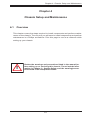
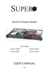
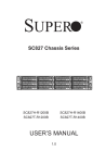
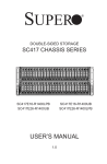
Figure 4-1: Removing the Chassis Cover
1. Remove the five screws that hold the chassis cover in place.There are two
screws on each side of the chassis, and one screw on the back.
2. Once the screws have been removed, lift the cover upward to remove it from
the chassis.
!
Warning: Except for short periods of time, do NOT operate the
server without the cover in place. The chassis cover must be in
place to allow proper airflow and prevent overheating.
RANGE
½d³ò
TOLERA
¤
X.xx
± 0
X.x
± 0
X
± 1
²Ä¤T¨¤ªk
THE 3RD PROJECTION
4-2
Chapter 4: Chassis Setup and Maintenance
4-3
B
Installing the Hard Drives
C
D
E
F
G
H
I
J
K
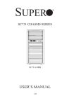
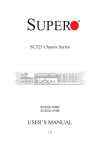
The 3.5" hard drive screws
directly into the chassis
C
D
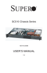
Figure 4-2: Installing the 3.5" Hard Drive
G
F
E
H
F
E
D
C
B
A
B
J
I
H
G
F
E
D
C
I
J
G
K
1
2
The 2.5" hard drives (1) must be installed
in their bracket (2) before they are
screwed into the chassis. (Bracket part
number is MCP-220-00044-0N)
3
1
4
2
RANGE
½d³ò
TOLERANC
¤½®
X.xx
± 0.1
X.x
± 0.2
X
± 1.0
²Ä¤T¨¤ªk
THE 3RD PROJECTION
5
6
7
8
Figure 4-3: Installing the 2.5" Hard Drives
4-3
C
D
E
F
SC502 Chassis Manual
4-4
G
H
I
J
K
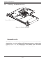
Installing the Motherboard
Chassis Standoffs
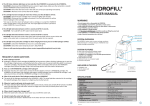
Figure 4-4: Chassis Standoffs
Chassis Standoffs
Standoffs prevent short circuits by securing space between the motherboard and the
chassis surface. The SC502 chassis includes permanent standoffs in locations used
by Micro ATX 9.6" x 9.6" size motherboards. These standoffs accept the rounded
Phillips head screws included in the SC502 accessories packaging.
RANGE
½d³ò
TOLERANC
¤½®
X.xx
± 0.1
X.x
± 0.2
X
± 1.0
²Ä¤T¨¤ªk
THE 3RD PROJECTION
4-4
Chapter 4: Chassis Setup and Maintenance
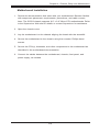
Motherboard Installation
1. Review the documentation that came with your motherboard. Become familiar
with component placement, requirements, precautions, and cable connections. The SC502 chassis supports 9.6" x 9.6" Micro ATX motherboards. Refer
to the Supermicro Web site for details or contact Supermicro for assistance.
2. Open the chassis cover.
3. Lay the motherboard on the chassis aligning the board with the standoffs.
4. Secure the motherboard to the chassis using the rounded, Phillips head
screws.
5. Secure the CPU(s), heatsinks, and other components to the motherboard as
described in the motherboard documentation.
6. Connect the cables between the motherboard, chassis, front panel, and
power supply, as needed
4-5
SC502 Chassis Manual
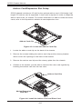
Add-on Card/Expansion Slot Setup
SC502 chassis includes an I/O slot for the optional add-on card. A full-height, halflength PCI add-on card is supported. A riser card is required in order to adapt the
add-on card to the 1U chassis. For further information on add-on cards and risers
cards, refer to the Supermicro website at www.supermicro.com
A
B
1
C
D
E
F
G
H
I
J
K
L
M
R E V I S I O N S / -×-q
DESCRIPTION
±Ô-z
REV
ª©¥»
LOCATION
¦ì¸m
2
3
4
Add-on Card Clip
5
Figure 4-5: Locate the Add-on Card Clip
6
1. Locate the add-on card clip on the back of the chassis
7
2. Remove the screws holding the add-on card clip and the dummy bracket
which covers the openings in the back of the chassis.
8
3. Remove the add-on card clip and the dummy plate from the chassis.
9
A
B
10
4. Outside of the chassis, put the add-on card and the riser card together by
inserting the add-on card into the riser card.
C
D
E
F
G
H
I
J
K
RANGE
½d³ò
TOLERANCE
¤½®t
X.xx
± 0.10
X.x
± 0.25
X
± 1.00
²Ä¤T¨¤ªk
THE 3RD PROJECTION
L
R E V I S I O N S / -×-q
DESCRIPTION
±Ô-z
REV
ª©¥»
A BLEC
Ablecom Technology Inc.
MATERIAL / §÷½è :
*
FINISH / ªí-±³B¸Ì :
See Note.
UNIT / ³æ¦ì :
MM
LOCATION
¦ì¸m
MODEL NO./ ¾÷«¬ :
M
SC502
¤j˚T¬ì§ÞªÑ¥÷¦³--¤½¥q
DRAWN / ø¹Ï :
SHO
DESIGN / ³]-p :
SHO
APPROVED / ¼f®Ö :
TITLE / «~¦W :
DATE / ¤é´Á:
13-Nov-07
SC502_SYSTEM_ASSY
DATE / ¤é´Á:
13-Nov-07
DATE / ¤é´Á:
SIZE/¹Ï®Ø
PART NO. / ®Æ¸¹ :
*
A0
SCALE / ¤ñ¨Ò :
DWG NO. / ¹Ï¸¹ :
*
Add-on Card Clip
Add-on/Expansion
Card Slot
Figure 4-6: Install the Add-on Card and Riser Card
4-6
1:1
Chapter 4: Chassis Setup and Maintenance
5. Insert the assembled add-on card and riser card into the expansion slot inside
the chassis, carefully aligning the plate of the add-on card with the openings
in the back of the chassis.
A
B
C
D
E
F
G
H
I
J
K
L
RE
DESCRIPTIO
±Ô
REV
ª©¥»
1
6. Replace the add-on card clip and screw it onto the chassis to hold the add-on
card in place.
2
3
4
5
6
Figure 4-7: Replace the Add-on Card
7
7. Replace the chassis cover.
8
A
B
C
D
E
F
G
H
I
J
K
REV
ª©¥»
9
10
1
2
RANGE
½d³ò
TOLERANCE
¤½®t
X.xx
± 0.10
X.x
± 0.25
X
± 1.00
²Ä¤T¨¤ªk
THE 3RD PROJECTION
3
4
5
6
Figure 4-8: Replace the Add-on Card Clip
7
4-7
8
A BLEC
M
Ablecom Technology Inc.
MATERIAL / §÷½è :
*
FINISH / ªí-±³B¸Ì :
See Note.
UNIT / ³æ¦ì :
MM
¤j˚T¬ì§ÞªÑ¥÷¦³-
DRAWN / ø¹Ï :
SHO
DESIGN / ³]-p :
SHO
APPROVED / ¼f®Ö :
DATE / ¤é´Á:
29-Nov-07
DATE / ¤é´Á:
29-Nov-07
DATE / ¤é´Á:
SC502 Chassis Manual
4-5
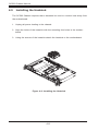
Installing the Heatsink
The SC502 Chassis requires that a heatsink be used to conduct heat away from
the motherboard.
1. Unplug all power leading to the chassis.
2. Align the holes of the heatsink with the mounting thru holes in the motherboard
3. Using the screws of the heatsink attach the heatsink to the motherboard.
A
B
C
D
E
F
G
H
I
J
K
L
REVIS
DESCRIPTION
±Ô-z
REV
ª©¥»
Figure 4-9: Installing the Heatsink
RANGE
½d³ò
TOLERANCE
¤½®t
X.xx
± 0.10
X.x
± 0.25
X
± 1.00
²Ä¤T¨¤ªk
THE 3RD PROJECTION
4-8
A BLEC
M
Ablecom Technology Inc.
MATERIAL / §÷½è :
*
FINISH / ªí-±³B¸Ì :
See Note.
UNIT / ³æ¦ì :
MM
¤j˚T¬ì§ÞªÑ¥÷¦³--¤½
DRAWN / ø¹Ï :
SHO
DESIGN / ³]-p :
SHO
APPROVED / ¼f®Ö :
DATE / ¤é´Á:
13-Nov-07
DATE / ¤é´Á:
13-Nov-07
DATE / ¤é´Á:
A
B
C
D
E
F
G
H
I
J
K
Chapter 4: Chassis Setup and Maintenance
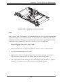
Figure 4-10: Installing an Active Heatsink
Note:
Intel Celeron 400 35W platform motherboards may require an optimized design
(SNK-P0032A4) active heatsink. Refer to Appendix A of this manual for basic
heatsink information. Refer to your motherboard documentation for detailed heatsink
information and installation instructions, specific to your motherboard.
Checking the Server's Air Flow
1. Make sure there are no objects to obstruct airflow in and out of the server.
2. Use only recommended server parts.
3. Make sure no wires or foreign objects obstruct air flow through the chassis.
Pull all excess cabling out of the airflow path, or use shorter cables.
4. The control panel LEDs inform you of system status. See “Chapter 3: System
Interface” for details on the LEDs and the control panel buttons.
4-9
RANGE
½d³ò
TOLERANCE
¤½®t
X.xx
± 0.10
X.x
± 0.25
X
± 1.00
²Ä¤T¨¤ªk
THE 3RD PROJECTION
A BLEC
Ablecom Techno
MATERIAL / §÷½è :
*
FINISH / ªí-±³B¸Ì :
See Note.
UNIT / ³æ¦ì :
MM
B
SC502 Chassis Manual
4-8
Power Supply
The SC502 chassis has a 200 watt power supply. This power supply is auto-switching capable. This enables it to automatically sense and operate at a 100v to 240v
input voltage.
The SC502 chassis has one power supply. In the unlikely event that the power
supply unit fails, the system will shut down and you will need to change the power
supply unit.
New units can be ordered directly from Supermicro (see contact information in the
Preface).
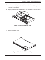
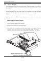
Replacing the Power Supply
1. Unplug all power leading to the chassis.
2. Disconnect all wiring from the power supply.
C
3. Remove the four screws which hold the power supply in the chassis. Two rear
mounting screws are located on the rear of the power supply. Two bottom
mounting screws are accessed on the underside of the chassis and extend
D
E
F
G
H
Rear Mounting Screws
Power Supply
Mounting Thru Holes
Bottom Mounting Screws
Figure 4-11: Installing the Power Supply
4-10
I
J
K
Chapter 4: Chassis Setup and Maintenance
upwards through the mounting thru holes, to hold the power supply in place.
Set the screws aside for later use.
4. Remove the power supply from the chassis.
5. Align the mounting thru holes on the power supply with the mounting holes
in the chassis and reattach the power supply to the chassis using the four
screws which were previously set aside
6. Connect the chassis wiring to the power supply.
4-11
SC502 Chassis Manual
Notes
4-12
Chapter 5: Rack Installation
Chapter 5
Rack Installation
5-1
Overview
This chapter provides a quick setup checklist to get your chassis up and running.
Following these steps in the order given should enable you to have the system
operational in a minimal amount of time.
5-2
Unpacking the System
You should inspect the box the chassis was shipped in, and note if it was damaged
in any way. If the chassis itself shows damage, you should file a damage claim with
the carrier who delivered it.
Decide on a suitable location for the rack unit that will hold your chassis. It should
be situated in a clean, dust-free area that is well ventilated. Avoid areas where
heat, electrical noise and electromagnetic fields are generated. You will also need
it placed near a grounded power outlet. Be sure to read the Rack and Server Precautions in the next section.
5-3
Preparing for Setup
The box your chassis was shipped in should include four mounting screws, which
you will need if you intend to install the system into a rack. Please read this section
in its entirety before you begin the installation procedure outlined in the sections
that follow.
Choosing a Setup Location
•
•
Leave enough clearance in front of the rack to enable you to open the front
door completely (~25 inches).
Leave approximately 30 inches of clearance in the back of the rack to allow for
sufficient airflow and ease in servicing.
5-1
SC502 Chassis Manual
•
This product is for installation only in a Restricted Access Location (dedicated
equipment rooms, service closets and similar environments).
!
Warnings and Precautions!
!
Rack Precautions
•
Ensure that the leveling jacks on the bottom of the rack are fully extended to
the floor with the full weight of the rack resting on them.
•
In single rack installation, stabilizers should be attached to the rack.
•
In multiple rack installations, the racks should be coupled together.
•
•
Always make sure the rack is stable before extending a component from the
rack.
You should extend only one component at a time. Extending two or more simultaneously may cause the rack to become unstable.
General Server Precautions
•
•
•
•
•
•
Review the electrical and general safety precautions that came with the components you are adding to your chassis.
Determine the placement of each component in the rack.
Install the heaviest server components on the bottom of the rack first, and then
work up.
Use a regulating, uninterruptible power supply (UPS) to protect the server from
power surges, voltage spikes and to keep your system operating in case of a
power failure.
Allow the hard drives and power supply modules to cool before touching
them.
Always keep the rack's front door, all panels and all components on the servers
closed when not servicing, in order to maintain proper cooling.
5-2
Chapter 5: Rack Installation
Rack Mounting Considerations
Ambient Operating Temperature
If installed in a closed or multi-unit rack assembly, the ambient operating temperature of the rack environment may be greater than the ambient temperature of the
room. Therefore, consideration should be given to installing the equipment in an
environment compatible with the manufacturer’s maximum rated ambient temperature (TMRA).
Reduced Airflow
Equipment should be mounted into a rack so that the amount of airflow required
for safe operation is not compromised.
Mechanical Loading
Equipment should be mounted into a rack so that a hazardous condition does not
arise due to uneven mechanical loading.
Circuit Overloading
Consideration should be given to the connection of the equipment to the power
supply circuitry and the effect that any possible overloading of circuits might have
on overcurrent protection and power supply wiring. Appropriate consideration of
equipment nameplate ratings should be used when addressing this concern.
Reliable Ground
A reliable ground must be maintained at all times. To ensure this, the rack itself
should be grounded. Particular attention should be given to power supply connections other than the direct connections to the branch circuit (for example, the use
of power strips, and other devices).
5-3
SC502 Chassis Manual
5-4
Rack Mounting Instructions
This section provides information on installing the SC502 chassis into a rack unit
There are a variety of rack units on the market, which may mean the assembly
procedure will differ slightly. You should also refer to the installation instructions that
came with the rack unit you are using.
Figure 5-1: Installing the Chassis into a Rack
Installing the Chassis into a Rack:
1. Confirm that chassis includes the four mounting screws required to mount the
chassis into a rack
2. Align the thru holes of the chassis with the thru holes of the rack.
3. Insert the mounting screws into the thru holes in the front of the chassis and
through the thru holes in the rack
5-4
Chapter 5: Rack Installation
Mid-Mount Telco Rack
The SC502 supports Telco Rack installation. The SC502 chassis compact design
allows the chassis to be installed into a Telco rack without the use of rails.
Figure 5-2: Installing the Chassis into a Telco Rack
Installing the Chassis into a Rack:
1. Confirm that chassis includes the four mounting screws required to mount the
chassis into a rack
2. Align the thru holes of the chassis with the thru holes of the rack.
3. Insert the mounting screws into the thru holes in the front of the chassis and
through the thru holes in the rack
5-5
SC502 Chassis Manual
Notes
5-6
Appendix A: Chassis Cables
Appendix A
Cables, Screws,
and other Accessories
A-1 Overview
This appendix lists supported cables for your chassis system. It only includes the
most commonly used components and configurations. For more compatible cables,
refer to the manufacturer of the motherboard you are using and our Web site at:
www.supermicro.com.
A-2 Cables Included with SC502 Chassis
SC502-200B
Part #
Type
CBL-0236L
-
Length
Ribbon
13"
Cable
6'
Description
16 pin to 16 pin ribbon cable for
control panel
Regional power cord
A-3 Optional Accessories
A
1
2
B
C
D
E
F
H
I
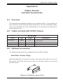
Hard Drive Carrier (Tray):
MCP-220-00044-0N 2.5" hard drive carrier. One carrier can hold up to two 2.5"
hard drives. The SC502 can hold up to two 2.5" hard drive carriers, for a total of
four hard drives.
3
4
Figure A-1: Hard Driver Carrier (Tray)
5
A-1
6
G
The following accessories are compatible with the SC502 Chassis.
J
SC502 Chassis Manual
1U Active Heatsink (SNK-P0032A4)
It is critical to choose the correct heatsink for your motherboard, that will fit in the
SC502 chassis.
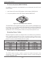
1. Intel Celeron 400 seriew (35W) platform: Active heatsink SNKP0032A4
2. Low power platforms under 20W: Passive heatsink SNKP0016P
Figure A-2: SNK-P00A4 Active Heatsink
The SNK-P00A4 active heatsink may only be used on specific motherboards, due
to its larger 4" x 4" size. This is particularly important in systems utilizing Intel
Celeron 400 series platforms. To ascertain which heatsink is appropriate for your
motherboard, refer to the Supermicro Web site at http://www.supermicro.com.
Extending Power Cables
Although Supermicro chassis are designed with to be efficient and cost-effective,
some compatible motherboards have power connectors located in different areas.
To use these motherboards you may have to extend the power cables to the mother
boards. To do this, use the following chart as a guide.
Power Cable Extenders
Number of Pins
Cable Part #
Length
24 pin
CBL - 0042
7.9”(20 CM)
20 pin
CBL - 0059
7.9”(20 CM)
8 pin
CBL - 0062
7.9”(20 CM)
4 pin
CBL - 0060
7.9”(20 CM)
Front Panel to the Motherboard
The SC502 chassis includes a cable to connect the chassis front panel to the
motherboard. If your motherboard uses a different connector, use the following list
to find a compatible cable.
A-2
Appendix A: Chassis Cables
Front Panel to Motherboard Cable (Ribbon Cable)
Number of Pins
(Front Panel)
Number of Pins
(Motherboard
Cable Part #
16 pin
16 pin
CBL - 0049
16 pin
20 pin
CBL - 0048
20 pin
20 pin
CBL - 0047
16 pin
various*
CBL - 0068
20 pin
various*
CBL - 0067
* Split Cables: Use these cable if your motherboard requires several different connections from the front panel.
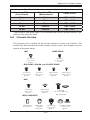
A-4 Chassis Screws
The accessory box includes all the screws needed to setup your chassis. This
section lists and describes the most common screws used. Your chassis may not
require all the parts listed.
M/B
HARD DRIVE
Flat head
6-32 x 5 mm
[0.197]
Pan head
6-32 x 5 mm
[0.197]
DVD-ROM, CD-ROM, and FLOPPY DRIVE
Pan head
6-32 x 5 mm
[0.197]
Flat head
6-32 x 5 mm
[0.197]
Round head
M3 x 5 mm
[0.197]
Round head
M2.6 x 5 mm
[0.197]
RAIL
Flat head
M4 x 4 mm
[0.157]
Round head
M4 x 4 mm
[0.157]
Flat head
M5 x 12 mm[0.472]
Washer for M5
M/B STANDOFFS
M/B standoff
6-32 to 6-32
M/B (CPU)
standoff
M5 to 6-32
Thumb screw
6-32 x 5 mm
[0.197]
A-3
1/U M/B standoff
6-32 x 5 mm
[0.197]
SC502 Chassis Manual
Notes
A-4
Appendix B: Power Supply Specifications
Appendix B
Power Supply Specifications
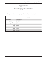
This appendix lists power supply specifications for your chassis system.
200W
MFR Part #
PWS-201-1H
Rated AC Voltage
100 - 240V
50 - 60Hz
4-2Amp
+5V standby 2 Amp
+12V
16 Amp
+5V
8 Amp
+3.3V
8 Amp
-12V
0.5 Amp
B-1
SC502 Chassis Manual
Notes
B-2